
Precast Mould Guide
RE Wall Panel Mould Quick-Release Border Setup: Corner Alignment, Edge Accuracy and Demoulding Sequence
Accurate quick-release border setup helps an RE wall panel mould produce straight edges, square corners and consistent joint profiles. This guide explains fixed-datum positioning, lock adjustment, slurry control and safe border removal.
By Paras Steel Industries ·
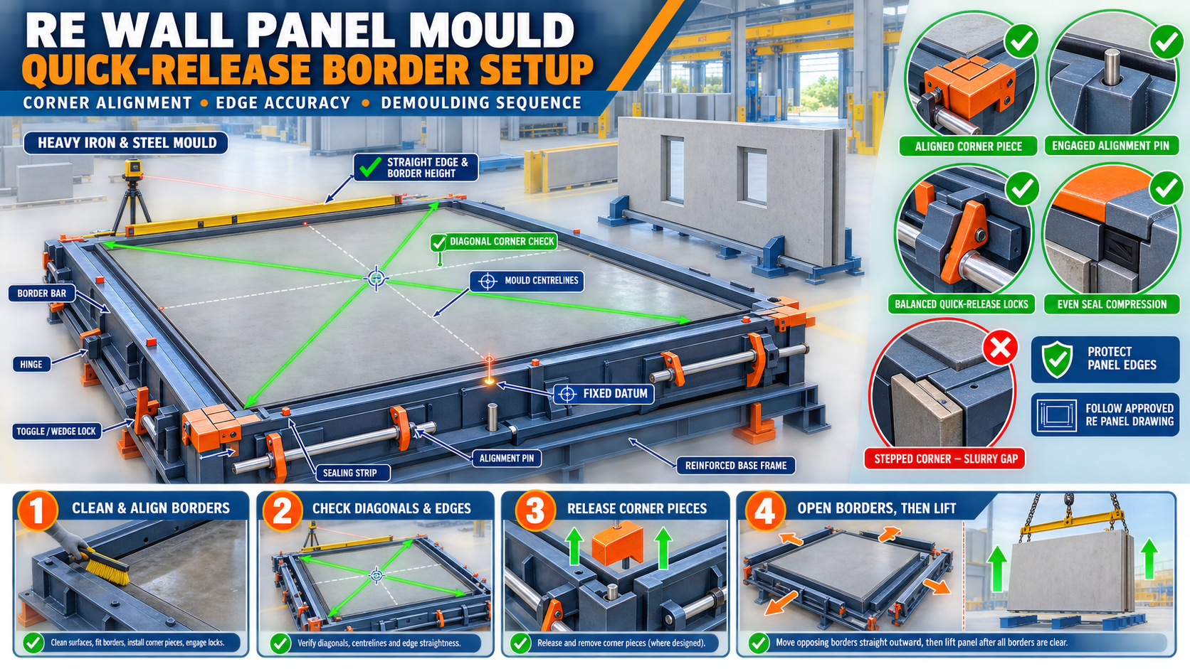
RE Wall Panel Mould Quick-Release Border Setup: Corner Alignment, Edge Accuracy and Demoulding Sequence
RE Wall Panel Mould Quick-Release Border Setup Guide
Reinforced earth wall panels are precast concrete facing units used in retaining-wall, highway, bridge-approach and infrastructure projects. Their outer edges and corner geometry must remain accurate so neighbouring panels can align correctly during installation.
A heavy-duty iron RE wall panel mould may use removable or hinged quick-release borders around the casting surface. These borders form the panel perimeter and allow the cured concrete unit to be demoulded without damaging its corners.
If the border is positioned incorrectly, the finished panel may have unequal sides, out-of-square corners, joint steps or concrete fins.
This guide explains RE wall mould quick release border setup, including fixed-datum positioning, corner alignment, edge-accuracy checks, balanced locking and safe demoulding.
What Is a Quick-Release Border?
A quick-release border is a removable or movable iron frame installed around the casting surface of an RE wall panel mould.
A typical border system may include:
• Heavy iron border bars • Corner joints • Hinges • Alignment pins • Locating blocks • Wedge locks • Toggle clamps • Bolts • Removable corner pieces • Sealing strips • Mechanical stops • Handles • Retaining pins • Lifting points where designed
The exact configuration should follow the approved RE wall panel drawing.
Purpose of the Border System
The mould border helps form:
• Panel length • Panel width • Panel thickness • Straight outer edges • Corner geometry • Chamfers • Joint profiles • Connection recesses • Lifting or insert clearances • Architectural-facing boundaries
It also provides access for controlled panel demoulding.
Why Border Alignment Is Important
Correct border alignment helps achieve:
• Accurate panel dimensions • Straight edges • Square or approved shaped corners • Consistent joint lines • Better fit between panels • Reduced concrete fins • Controlled slurry leakage • Easier demoulding • Lower corner damage • Repeatable panel production
One displaced border can affect several installation relationships.
RE Wall Panel Shapes
RE wall panels may be produced in:
• Cruciform shapes • Square shapes • Rectangular shapes • Custom facing shapes • Full panels • Half panels • Corner or closure panels • Project-specific profiles
The quick-release border arrangement must match the selected panel shape.
Safety Before Border Setup
Borders can be heavy and may move suddenly after the final lock is released.
Before setup or maintenance:
1. Stop mould production. 2. Remove the finished panel and loose materials. 3. Isolate hydraulic or powered mechanisms where fitted. 4. Apply the plant’s lockout and tagout procedure. 5. Position the mould on a stable, level base. 6. Support hinged or removable borders mechanically. 7. Inspect handling equipment. 8. Keep hands away from corner pinch points. 9. Use approved lifting points. 10. Wear suitable personal protective equipment.
Never stand in the movement path of an unsecured border.
Clean the Mould Before Setup
Hardened concrete can prevent complete border closure.
Clean:
• Casting surface • Border contact faces • Corner joints • Alignment-pin holes • Locating blocks • Hinges • Locks • Seal grooves • Liner edges • Mechanical stops • Insert recesses • Base-frame references
Take alignment measurements only after cleaning.
Inspect the Quick-Release Borders
Check every border component for:
• Straightness • Local bending • Twisting • Cracked welds • Damaged corners • Worn hinges • Bent pins • Enlarged holes • Damaged locking brackets • Corrosion • Concrete buildup • Previous unapproved repairs • Distorted handles • Damaged lifting points
A bent border should not be forced into place using its locks.
Inspect the Mould Base
Border alignment depends on a flat and stable base.
Check:
• Casting-surface flatness • Base-frame level • Structural supports • Welded joints • Modular connections • Liner position • Local distortion • Concrete buildup underneath • Anchor points • Levelling arrangements
Correct base problems before adjusting the borders.
Establish a Fixed Datum
A fixed datum provides a repeatable reference for every border.
The datum may be:
• One mould corner • Mould centreline • Machined locating block • Fixed end stop • Alignment rail • Survey reference
Position each border from the same datum.
Avoid Cumulative Measurements
Do not position every border only from the previously installed one. Small errors may accumulate around the mould perimeter.
Instead:
• Mark all border locations from the datum • Check opposite borders independently • Verify diagonals • Check the final corner against the starting reference • Record measurements • Recheck after locking
This reduces accumulated alignment error.
Identify Each Border Component
Before installation, confirm:
• Panel type • Border identification • Top and bottom edges • Left and right sides • Corner-piece location • Joint-profile direction • Chamfer orientation • Liner compatibility • Fixed and removable sections
Incorrectly interchanged components may appear similar but produce different panel edges.
Initial Border Positioning
A practical setup sequence is:
1. Clean the mould surface. 2. Confirm the panel drawing. 3. Establish the fixed datum. 4. Position the first fixed border. 5. Install adjacent borders loosely. 6. Engage locating blocks and pins. 7. Fit corner pieces. 8. Engage all locks lightly. 9. Check dimensions and diagonals. 10. Complete final locking only after alignment.
Do not fully tighten the first border before placing the remaining components.
Corner Alignment
Corners control both panel dimensions and edge quality.
At each corner, inspect:
• Border-end contact • Alignment-pin engagement • Corner-piece seating • Internal corner step • External border step • Joint gap • Chamfer continuity • Seal position • Lock engagement • Welded reinforcement
The border faces should meet according to the approved profile.
Checking Corner Squareness
Where the design requires square corners, use an approved square, diagonal measurement or fixed checking template.
Check:
• Each individual corner • Opposite corner relationship • Mould diagonals • Border straightness • Liner-to-border alignment • Position after locking
For cruciform or custom panels, use the approved profile template instead of assuming all corners are square.
Diagonal Measurement
A controlled diagonal check may include:
1. Clean the reference points. 2. Identify matching corners. 3. Measure both approved diagonals. 4. Use the same instrument and method. 5. Compare the readings. 6. Adjust borders gradually. 7. Recheck after locking. 8. Record the final result.
Acceptable differences must follow the approved mould drawing.
Check Corner Height
Borders should also remain at the required height relative to the casting surface.
Unequal border height may cause:
• Variable panel thickness • Uneven top edges • Poor finishing reference • Incorrect chamfer position • Installation mismatch
Check height at corners and intermediate points.
Edge Straightness
Long border members can bow between their supports or locks.
Check edge straightness:
• Along every side • Between locks • Near corner joints • At modular sections • Around previous repair areas • After tightening • During planned maintenance
Use a straightedge, string line, laser or approved survey method.
Edge Accuracy Checks
Edge accuracy may include:
• Overall length • Overall width • Border straightness • Corner position • Chamfer continuity • Joint-profile geometry • Thickness reference • Insert clearance • Liner-edge alignment
All checks should follow the approved panel drawing.
Border Parallelism
Opposite borders should maintain the intended relationship.
Check:
• Distance at both ends • Distance near the centre • Border-to-centreline position • Top-to-bottom relationship • Opposite joint-profile alignment
Parallel borders help maintain consistent panel width.
Quick-Release Lock Inspection
The locking system should pull each border into its designed position without bending it.
Inspect:
• Wedge locks • Toggle clamps • Pins • Bolts • Lock brackets • Handles • Contact pads • Retainers • Threads • Welded supports
Replace damaged parts before casting.
Balanced Locking Sequence
A suitable locking sequence is:
1. Engage all locating pins. 2. Confirm corner-piece positions. 3. Close every lock lightly. 4. Tighten opposing borders gradually. 5. Work around the mould in a balanced sequence. 6. Check corner contact. 7. Inspect seal compression. 8. Recheck diagonals. 9. Verify border height. 10. Complete final engagement.
The exact sequence should follow the mould design.
Avoid Over-Tightening
Excessive lock pressure can:
• Bend border bars • Crush seals • Pull corners out of alignment • Distort the liner • Damage locking brackets • Make demoulding difficult • Change panel dimensions
Locks should secure an aligned border, not force a damaged border into position.
Avoid Under-Tightening
Insufficient locking may allow:
• Border movement • Slurry leakage • Concrete fins • Dimensional variation • Lock loosening during vibration • Chamfer displacement
Check all locks before concrete placement.
Inspect Alignment Pins
Alignment pins help establish repeatable border position.
Check for:
• Bending • Wear • Scoring • Corrosion • Concrete buildup • Enlarged locating holes • Missing retainers • Incorrect pin type • Loose mounting • Damaged taper
Do not use a lock to compensate for a missing or damaged alignment pin.
Slurry Control at Border Joints
Concrete slurry can escape through small gaps and form fins on panel edges.
Common leakage locations include:
• Corners • Bottom border joint • Removable corner pieces • Liner-border interface • Bolt penetrations • Modular joints • Damaged seal sections • Misaligned locks
Identify the source rather than repeatedly removing fins from finished panels.
Inspect Sealing Materials
Where the mould uses gaskets or sealing strips, check for:
• Cuts • Cracks • Hardening • Flattening • Missing sections • Incorrect positioning • Concrete contamination • Oil damage • Uneven compression
Use only compatible sealing material according to the mould design.
Liner-to-Border Alignment
RE wall panel moulds may use cruciform, square or custom facing liners.
Check:
• Liner orientation • Pattern centreline • Border clearance • Pattern cutoff at the edges • Liner joint position • Border overlap • Fastening components • Surface continuity
Misalignment can create uneven architectural borders.
Chamfer Inspection
Chamfers help protect panel edges and may form part of the approved joint profile.
Inspect:
• Chamfer-strip position • Corner continuity • Straightness • Secure fastening • Damage • Slurry gaps • Liner compatibility • Demoulding direction
Loose chamfer components can shift during vibration.
Reinforcement and Insert Clearance
After border alignment, check:
• Reinforcement cover • Cage position • Connection inserts • Lifting anchors • Tie-strip connections • Bearing details • Spacer stability • Clearance from borders • Clearance from liner surfaces
Reinforcement or inserts should not push the borders out of position.
Apply Mould-Release Agent
Apply a suitable release agent to the clean iron border and casting surfaces.
The release agent should be:
• Compatible with precast concrete • Suitable for iron and liner surfaces • Applied in a thin uniform layer • Prevented from pooling • Kept away from required bond areas • Used according to its manufacturer’s instructions
Excessive application can affect surface quality.
Pre-Casting Border Checklist
Before concrete placement, verify:
• Correct panel configuration • Fixed-datum position • Border identification • Corner alignment • Diagonal checks • Edge straightness • Border height • Lock engagement • Alignment pins • Seal compression • Chamfers • Liner alignment • Reinforcement position • Insert locations • Release-agent application
Record the inspection according to the plant’s quality plan.
Concrete Placement
Place concrete in a balanced sequence.
During casting:
• Avoid heavy impact on one border • Distribute concrete progressively • Monitor border movement • Check locks • Observe corners for leakage • Maintain reinforcement position • Control the filling rate • Stop if a border shifts
Uneven concrete pressure may move a poorly secured border.
Controlled Vibration
Vibration should compact concrete without loosening the border system.
During vibration:
• Use the approved vibration equipment • Avoid excessive vibration • Check locking points • Monitor slurry leakage • Observe border movement • Keep reinforcement stable • Stop if abnormal noise develops
Do not adjust loaded border locks without an approved safe procedure.
When Should Demoulding Begin?
Border release should only begin after the concrete reaches the required stripping condition.
The decision depends on:
• Concrete mix • Cement type • Temperature • Curing method • Panel size • Edge profile • Lifting arrangement • Approved production procedure
Do not release borders only because a fixed number of hours has passed.
Prepare for Demoulding
Before releasing the border:
1. Confirm stripping approval. 2. Clear the working area. 3. Remove slurry around locks. 4. Inspect lifting anchors. 5. Prepare the approved lifting system. 6. Support removable border components. 7. Identify the release sequence. 8. Keep workers away from movement paths. 9. Protect panel edges. 10. Confirm the mould base is stable.
A quick-release border should still be opened in a controlled manner.
Recommended Demoulding Sequence
The actual sequence should follow the mould design, but a controlled approach may include:
1. Remove exposed concrete and slurry from locking points. 2. Support removable corner pieces. 3. Release locks gradually. 4. Remove or open corner pieces first where designed. 5. Release opposing borders in a balanced order. 6. Move borders directly away from the panel. 7. Avoid dragging borders across concrete edges. 8. Confirm all components are clear. 9. Lift the panel using approved anchors. 10. Place it on stable supports. 11. Inspect the edges and corners. 12. Clean the mould immediately.
Never force the panel upward while a border remains engaged.
Why Corner Pieces May Be Released First
Where the design includes removable corners, releasing them may create clearance for the long border members.
This can help:
• Reduce corner pressure • Prevent concrete chipping • Allow straight border movement • Protect chamfers • Reduce binding
Only follow this approach when it matches the approved mould design.
Controlled Border Movement
Borders should move:
• In their designed release direction • Slowly and evenly • Without twisting • Without scraping the panel • With mechanical support where necessary • Clear of lifting anchors and inserts
Stop if the border binds.
Edge Protection During Demoulding
To protect panel edges:
• Confirm adequate concrete condition • Release locks gradually • Remove slurry from joints • Move borders directly outward • Avoid steel hammering on concrete • Use approved protective pads • Control panel lifting • Keep the panel level • Place it on suitable dunnage
Corner damage should be investigated before the next casting.
Common Demoulding Problems
Border Does Not Release
Check unreleased locks, slurry entry, concrete sticking, damaged hinges and distorted border members.
Corner Breaks During Opening
Possible causes include early demoulding, rough border surfaces, incorrect release direction or damaged chamfers.
Border Scratches the Panel Edge
The border may be moving sideways, sagging or binding at a corner.
Panel Lifts With the Border
Inspect release-agent coverage, slurry penetration, concrete buildup and release sequence.
Corner Piece Is Difficult to Remove
Check alignment pins, slurry buildup, taper, lock release and concrete condition.
Locks Are Difficult to Open
Possible causes include over-tightening, slurry entry, border distortion and concrete pressure remaining on the system.
Common Setup Problems and Corrections
Diagonals Are Unequal
Re-establish border positions from the fixed datum and correct corners before final locking.
One Edge Is Bowed
Inspect the border bar, intermediate locks, stiffeners and previous repairs.
Concrete Fin Appears Along the Edge
Check the bottom joint, seal condition, flange cleanliness and lock pressure.
Panel Width Changes Along Its Length
Inspect opposite-border parallelism and long-border straightness.
Corner Pattern Does Not Match the Liner
Check liner orientation, border position and corner-piece identification.
Border Height Varies
Inspect locating blocks, concrete buildup, base flatness and bent border members.
Post-Demoulding Panel Inspection
Check the finished RE wall panel for:
• Overall dimensions • Diagonal relationship • Edge straightness • Corner condition • Panel thickness • Joint profile • Chamfer continuity • Surface pattern • Concrete fins • Cracks • Honeycombing • Insert position
Final acceptance should follow the approved project requirements.
Border Maintenance
After every casting cycle:
• Clean borders and corners • Remove slurry from locks • Clean alignment pins • Inspect sealing surfaces • Lubricate hinges and approved moving parts • Check border straightness • Inspect handles and retainers • Protect iron surfaces from corrosion
Scheduled checks should include:
• Diagonal setup verification • Lock-wear inspection • Hinge and bush inspection • Seal replacement • Corner-piece profile checks • Base-frame flatness • Liner-border alignment • Weld inspection • Trial setup and release test
Store removable borders on stable supports.
When Should Production Be Stopped?
Stop using the RE wall panel mould if you find:
• Severely bent borders • Cracked structural welds • Broken alignment pins • Failed locks • Damaged lifting points • Borders that cannot release safely • Major slurry leakage • Incorrect panel diagonals • Repeated corner breakage • Unstable mould supports • Distorted liners • Inability to maintain edge accuracy
Production should resume only after repair and dimensional verification.
Conclusion
Correct RE wall mould quick release border setup begins with a clean, level mould and one fixed datum. Borders should be positioned with aligned corners, straight edges, correct height and balanced lock engagement.
During demoulding, corner pieces and borders must be released in the sequence intended by the mould design. Controlled outward movement helps protect panel edges and architectural facing details.
Paras Steel Industries manufactures heavy-duty iron and structural-steel RE wall panel moulds according to customer requirements and approved drawings. Accurate border setup and planned demoulding help support consistent panel dimensions, cleaner corners and reliable site installation.