
Precast Mould Guide
RE Wall Panel Mould Liners: Cruciform, Square and Custom Facing Designs
RE wall panel mould liners create the visible architectural pattern on precast reinforced-earth wall panels. This guide compares cruciform, square and custom facing designs while explaining liner alignment, installation, production and maintenance.
By Paras Steel Industries ·
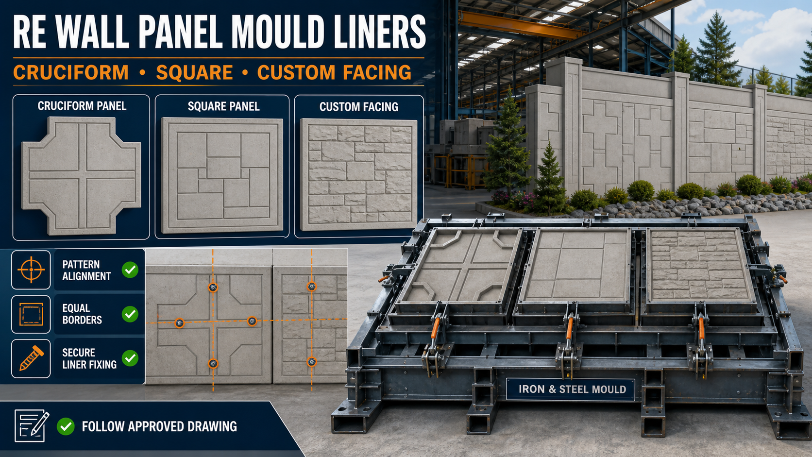
RE Wall Panel Mould Liners: Cruciform, Square and Custom Facing Designs
RE Wall Panel Mould Liners: Cruciform, Square and Custom Facing Designs
Reinforced-earth retaining walls use precast concrete facing panels to create a stable and visually consistent external surface. The shape and finish of these panels are produced using accurately fabricated RE wall panel moulds and facing liners.
Mould liners or patterned facing plates form the visible texture, grooves, recesses and architectural design on the finished concrete panel.
Cruciform, square and custom-facing panels require different mould layouts. Accurate liner positioning is essential because even a small alignment error can become clearly visible after several panels are installed together.
Paras Steel Industries manufactures precast moulds using iron and heavy-duty steel components. Panel dimensions, facing patterns, connection details and production arrangements can be customized according to the customer’s approved drawings.
What Is an RE Wall Panel Mould Liner?
An RE wall panel mould liner is a patterned facing component installed on the casting surface of a reinforced-earth wall panel mould.
When concrete is poured and compacted, the liner transfers its pattern to the visible face of the precast panel.
Depending on the approved design, the liner may form:
• Architectural textures • Recessed grooves • Raised patterns • Stone-like facing • Brick-style patterns • Geometric designs • Project logos or symbols • Panel-edge detailing • Joint-line patterns
The liner or facing plate must remain securely positioned throughout concrete filling and vibration.
What Is a Cruciform RE Wall Panel?
A cruciform panel has an extended cross-like profile. Its projecting portions connect visually with adjacent panels when the reinforced-earth wall is assembled.
The mould must reproduce:
• Central panel body • Horizontal extensions • Vertical extensions • Panel-edge geometry • Required joint clearances • Facing pattern • Connection-component positions • Lifting-point locations
Cruciform panels are commonly used where the approved retaining-wall system requires an interlocking or staggered panel arrangement.
Cruciform Mould-Liner Requirements
A cruciform liner should match the complete cross-shaped casting area. Pattern lines must continue correctly across every extension.
Important checks include:
• Liner centreline • Pattern direction • Alignment between extensions • Corner detailing • Joint-edge clearance • Fixing-point position • Surface flatness • Consistent pattern depth
Incorrectly positioned patterns can become visually misaligned after installation.
What Is a Square RE Wall Panel?
A square RE wall panel uses a square or nearly rectangular facing profile, depending on the approved design.
Square panels can simplify mould layout and production planning. However, their edges, diagonals and pattern positions must remain accurate to create uniform joint lines on the completed wall.
A square panel mould may include:
• Heavy-duty iron or steel casting base • Profiled side shutters • Removable end shutters • Patterned facing liner or steel facing plate • Connection-component fixtures • Lifting-insert formers • Structural channels and stiffeners • Mechanical or hydraulic locking systems
Square Panel Liner Requirements
The liner pattern should be centred according to the panel drawing. Borders and grooves must remain parallel to the panel edges.
Before casting, check:
• Panel length and width • Diagonal measurements • Squareness • Border width • Groove position • Pattern orientation • Liner fixing • Connection and lifting-insert positions
Unequal diagonal measurements may indicate that the mould is out of square.
Cruciform vs Square Facing Designs
Panel Shape
A cruciform panel has projecting extensions, while a square panel uses a simpler four-sided profile.
Mould Complexity
Cruciform moulds generally require more detailed shutter geometry. Square moulds can have a simpler perimeter but still require precise dimensions and alignment.
Pattern Continuity
Cruciform liners must maintain the facing pattern across the central body and extended portions. Square liners must maintain equal borders and straight pattern lines.
Production Changeover
Changing between cruciform and square panels may require different shutters, facing plates or complete mould setups.
Site Installation
The panel profile, joint arrangement and connection details must match the approved reinforced-earth wall system.
Neither design should be selected only by appearance. The project engineer or system designer must specify the required panel shape.
Common Facing-Liner Designs
Smooth Facing
A smooth facing creates a clean concrete surface with minimal decorative detailing. It requires a well-maintained casting surface because scratches, weld marks and dents may transfer to the panel.
Horizontal Groove Pattern
Horizontal grooves create continuous visual lines across the finished wall. Accurate vertical positioning is essential so the grooves align between adjoining panels.
Vertical Groove Pattern
Vertical grooves can emphasize panel height. The groove formers must remain parallel and correctly spaced.
Square or Rectangular Block Pattern
This pattern creates the appearance of masonry blocks. Border dimensions and intersection points should be consistent across every mould.
Stone-Texture Pattern
A stone-style pattern creates an architectural finish. Pattern repetition should be planned carefully so the completed wall does not appear unnatural.
Brick-Style Pattern
Brick-style liners reproduce brick courses and mortar joints. Adjacent panels must be coordinated to maintain consistent horizontal levels.
Custom Geometric Pattern
Custom patterns may include diamonds, waves, ribs, stepped lines or project-specific architectural designs.
Logo or Symbol Facing
Where approved, a liner can reproduce a logo, identification mark or decorative symbol. The design must allow clean demoulding and should avoid problematic undercuts.
Custom Facing Design Process
A custom facing design should begin with an approved architectural drawing.
The development process may include:
1. Review the required panel profile. 2. Confirm the visible wall layout. 3. Prepare a full-scale pattern drawing. 4. Check pattern continuation across adjoining panels. 5. Determine the required relief depth. 6. Remove problematic undercuts. 7. Select suitable fixing arrangements. 8. Produce a sample or trial panel. 9. Inspect the finished texture and alignment. 10. Approve the pattern before full production.
A trial casting can identify demoulding problems, trapped air or inconsistent pattern depth.
Liner or Facing-Plate Installation
The facing component should be installed on a clean, flat mould base.
A typical installation process includes:
• Clean the mould surface. • Mark the mould centreline. • Position the facing plate or liner. • Check orientation and pattern direction. • Measure borders from every panel edge. • Secure all fixing points. • Seal joints where required. • Check surface flatness. • Apply a suitable release agent. • Reinspect before placing reinforcement.
The fixing system must prevent the liner from floating, shifting or lifting during vibration.
Importance of Pattern Alignment
An RE wall is assembled using many individual panels. A small error repeated across multiple panels can become a visible installation problem.
Pattern alignment affects:
• Horizontal groove continuity • Vertical joint appearance • Border consistency • Architectural symmetry • Logo positioning • Visual quality of the completed wall
Reference lines should be marked on the mould and checked before every production cycle.
Liner Joint Details
Large facing designs may require more than one liner or plate section. Their joints should be positioned carefully.
Poorly designed liner joints may cause:
• Visible seam lines • Concrete fins • Slurry leakage • Pattern interruption • Surface-level differences • Difficult demoulding
Joint positions should ideally form part of the approved architectural pattern or be located where they are less visible.
Release-Agent Application
The release agent helps separate the concrete from the mould and patterned facing surface.
Apply a thin and uniform coat. Excessive release agent may collect inside grooves and affect the concrete colour or texture.
Before application:
• Remove concrete residue. • Clean dust and oil. • Inspect pattern recesses. • Confirm that joints are sealed. • Use a release agent compatible with the mould surface and concrete finish.
Do not allow thick pools of release agent inside the liner pattern.
Reinforcement and Connection Components
RE wall panels normally contain reinforcement and project-specific connection components.
The mould may require fixtures for:
• Reinforcement cage positioning • Soil-reinforcement connectors • Lifting anchors • Handling inserts • Alignment components • Identification recesses
All inserts must be positioned according to the approved structural drawing.
RE Wall Panel Production Process
A typical production cycle includes:
1. Clean the iron or steel mould. 2. Inspect the facing liner or patterned plate. 3. Check pattern alignment. 4. Apply a suitable mould-release agent. 5. Position the reinforcement cage. 6. Install connection and lifting components. 7. Close and lock the shutters. 8. Verify panel dimensions and diagonals. 9. Pour concrete uniformly. 10. Compact the concrete carefully. 11. Finish the rear surface. 12. Cure the panel correctly. 13. Demould after sufficient strength is achieved. 14. Inspect the facing pattern and edges. 15. Store the panel on suitable supports.
Vibration should compact the concrete without moving the facing liner or embedded components.
Common Facing Defects
Air Voids in the Pattern
Deep grooves and textured areas may trap air. Concrete placement and vibration should be adjusted to fill the complete pattern.
Misaligned Pattern
This may result from incorrect liner positioning, inadequate fixing or movement during vibration.
Concrete Fins
Open joints can allow cement slurry to enter gaps, creating fins that require finishing.
Uneven Pattern Depth
A bent facing plate, damaged liner or accumulated concrete residue may change the relief depth.
Sticking During Demoulding
Possible causes include inadequate cleaning, incorrect release-agent application, undercut patterns or premature demoulding.
Surface Discolouration
Uneven release-agent application, contamination or inconsistent concrete can affect the panel’s appearance.
Cleaning and Maintenance
After every casting cycle:
• Remove concrete residue carefully. • Clean grooves and textured recesses. • Inspect the facing plate for dents. • Check liner fixing points. • Repair open joints. • Inspect shutter alignment. • Check structural channels and welds. • Replace damaged pattern components. • Verify pattern dimensions periodically. • Store removable liners on flat supports.
Do not use tools that scratch or deform the facing surface.
Factors to Check Before Buying
Before ordering an RE wall panel mould or liner, provide:
• Approved panel drawing • Cruciform or square profile • Panel dimensions • Facing-pattern drawing • Required relief depth • Border and groove dimensions • Reinforcement details • Connection-component positions • Lifting-insert locations • Required production quantity • Manual or hydraulic operation • Vibration arrangement • Required dimensional tolerance • Sample finish or reference image
Complete details help the mould manufacturer evaluate the correct iron or steel frame, shutter arrangement, stiffeners and facing system.
Conclusion
Cruciform, square and custom RE wall panel designs require accurate mould geometry and consistent facing-pattern alignment.
The correct mould liner or patterned facing plate should reproduce the approved architectural finish without shifting during concrete filling and vibration. Regular cleaning and dimensional inspections are essential for maintaining consistent results.
Paras Steel Industries manufactures heavy-duty iron and steel precast moulds according to customer drawings, facing requirements and production targets. Buyers should provide the complete panel and pattern design before mould manufacturing begins.