
Precast Infrastructure Moulds
RE Wall Panel Mould Lifting-Socket Recess Former: Positioning, Concrete Cover and Removal Guide
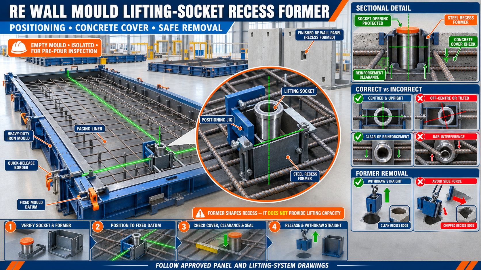
A lifting-socket recess former creates controlled access around an engineered lifting insert in a precast RE wall panel. Incorrect positioning, insufficient concrete cover or difficult former removal can damage the recess and affect safe handling. This guide explains accurate setup, reinforcement clearance and removal from a heavy-duty iron mould.
By Paras Steel Industries ·
RE Wall Panel Mould Lifting-Socket Recess Former: Positioning, Concrete Cover and Removal Guide
RE Wall Panel Mould Lifting-Socket Recess Former: Positioning, Concrete Cover and Removal Guide
Precast reinforced-earth wall panels must be safely demoulded, transported and installed using the lifting system specified by the project engineer and lifting-component supplier.
An embedded lifting socket may be used as part of an engineered lifting system. A removable recess former creates the access pocket around that socket so the approved lifting clutch, bolt or attachment can connect correctly.
The recess former does not provide lifting capacity by itself. Its function is to create the required concrete recess while holding the lifting socket in its approved position during reinforcement assembly and concrete casting.
What Is a Lifting-Socket Recess Former?
A lifting-socket recess former is a removable shaping component installed inside the RE wall panel mould.
It creates a controlled recess around the head or connection point of the embedded lifting socket.
The assembly may include:
• Engineered lifting socket • Removable recess former • Positioning bolt or threaded fixing • Locating jig • Reinforcement support • Mould mounting bracket • Sealing component • Identification marking • Removal tool
The exact system depends on the approved panel and lifting drawings.
Function of the Recess Former
A correctly installed former helps:
• Maintain lifting-socket position • Create access around the socket • Control recess shape • Prevent concrete from blocking the connection • Support repeatable insert placement • Improve lifting-attachment access • Reduce concrete chipping • Simplify former removal • Maintain consistent panel appearance
The recess profile should be compatible with the selected lifting system.
RE Wall Panel Mould Construction
A heavy-duty iron RE wall panel mould may include:
• Steel casting bed • Quick-release border shutters • Interchangeable facing liner • Side and corner locks • Structural stiffeners • Dimensional locating stops • Reinforcement-cage supports • Insert-positioning jigs • Lifting-socket former brackets • Slurry-sealing surfaces
All components must remain aligned to maintain the panel dimensions and insert positions.
Why Lifting-Socket Position Is Critical
An incorrectly positioned socket may cause:
• Difficulty connecting lifting equipment • Incorrect lifting direction • Unequal load distribution • Insufficient concrete cover • Interference with reinforcement • Concrete breakout risk • Edge damage • Panel imbalance • Damage during demoulding • Rejection of the finished panel
Lifting-insert design and acceptance should only be performed using approved engineering information.
Approved Drawings and Supplier Instructions
Before production, confirm the latest approved documents for:
• Panel dimensions • Panel weight • Concrete specification • Lifting-socket type • Socket location • Embedment arrangement • Reinforcement around the insert • Required concrete cover • Recess-former profile • Lifting direction • Demoulding requirement • Installation lifting arrangement
Never select insert locations or capacities only from a previous project.
What Is Concrete Cover?
Concrete cover is the specified distance between reinforcement or an embedded component and the relevant concrete surface.
Adequate cover supports:
• Proper concrete confinement • Reinforcement protection • Durability • Insert performance • Reduced surface cracking • Correct recess geometry
Required cover varies with the approved design, exposure conditions and lifting system. Generic values should not be assumed.
Positioning References for a Recess Former
The former should be positioned using fixed mould datums.
Possible reference points include:
• Panel mould centreline • Quick-release border datum • Fixed steel locating stop • Liner reference marks • Reinforcement-jig centreline • Approved insert-positioning template
Do not measure from a movable or unverified mould component.
Locating the Socket Centreline
To position the lifting socket accurately:
• Mark the approved panel centreline • Identify the lifting-point coordinates • Use a fixed jig or template • Check both horizontal directions • Check the socket’s vertical orientation • Confirm its relationship with the panel edges • Verify compatibility with reinforcement • Recheck before concrete placement
Visual judgement alone is not suitable for lifting-insert positioning.
Using a Positioning Jig
A positioning jig helps maintain repeatability across multiple panels.
A reliable jig should:
• Reference a fixed mould datum • Hold the former securely • Control socket position • Prevent rotation • Remain accessible for inspection • Resist vibration • Be easy to clean • Avoid interference with shutters • Carry clear identification
The jig itself should be checked periodically for wear, bending and loose connections.
Checking Socket Orientation
The socket should follow the orientation specified by the lifting-system drawing.
Check that:
• Connection axis is correct • Socket is not tilted • Threaded section is protected • Recess former seats concentrically • Insert body is stable • Reinforcement connection is correct • Lifting-access direction remains unobstructed
A socket that is correctly centred but tilted may still be unsuitable.
Reinforcement Clearance
The reinforcement cage should support the approved insert arrangement without pushing the socket away from its datum.
Check:
• Reinforcement follows the approved drawing • Bars do not obstruct the socket • Required concrete cover is maintained • Additional insert reinforcement is installed where specified • Tie wire does not enter the socket • Cage spacers remain stable • The former does not deform reinforcement • Insert fixtures remain accessible
Do not cut or move reinforcement without engineering approval.
Checking Concrete Cover
Concrete cover should be verified using approved measuring methods before casting.
The inspection may include:
• Socket distance from the panel face • Distance from panel edges • Clearance from reinforcement bars • Clearance from liner surface • Embedment position • Recess-former depth • Supporting-jig position
All acceptance criteria should come from the approved design.
Recess Former Types
Recess formers may vary according to the selected lifting system.
Possible forms include:
• Circular former • Hemispherical former • Tapered former • Conical former • Project-specific shaped former • Split removable former • Flexible former approved by the insert supplier • Steel former with a mechanical release
The former material and geometry must be compatible with concrete casting and the lifting attachment.
Iron or Steel Recess Former
A machined or fabricated steel former can provide:
• Dimensional stability • Repeated use • Accurate positioning • Controlled surface profile • Compatibility with an iron mould fixture
It should have an approved demoulding shape and smooth forming surface.
A damaged or undercut steel former may become trapped in the concrete.
Preparing the Former Before Installation
Before each casting cycle:
• Remove all concrete residue • Clean the forming surface • Inspect the taper • Check the mounting thread or fixing • Inspect for bending or dents • Confirm the former identity • Check its compatibility with the socket • Inspect the release arrangement • Apply approved release agent • Keep the socket connection clean
Do not use a former with damaged threads or an incorrect profile.
Protecting the Socket Opening
Concrete must not enter the lifting-socket connection.
Protection may involve an approved:
• Threaded plug • Sealing cap • Former connection • Protective cover • Supplier-specified closure
Improvised materials may become trapped or fail to protect the socket.
Installing the Former and Socket
A general setup sequence may include:
1. Verify Component Identity
Confirm the socket and former match the approved lifting system.
2. Clean All Components
Remove concrete, oil contamination and debris.
3. Assemble the Socket and Former
Connect them according to the supplier’s instructions.
4. Position the Assembly in the Jig
Reference the fixed mould datum.
5. Check Centreline and Orientation
Confirm the assembly is not tilted or rotated.
6. Verify Reinforcement Clearance
Check surrounding bars and cover.
7. Secure the Fixture
Prevent movement during concrete placement.
8. Inspect the Seal
Confirm concrete cannot enter the socket connection.
9. Record the Pre-Pour Check
Complete the required quality documentation.
Preventing Former Movement
A recess former may move due to:
• Loose fixture • Concrete impact • Reinforcement pressure • Vibration • Damaged jig • Incorrect thread engagement • Inadequate support • Mould movement • Improper installation
The former should remain mechanically secured throughout casting.
Slurry Sealing Around the Former
A gap between the former and socket can allow cement slurry to enter the connection or create a concrete fin.
Before casting:
• Check concentric fit • Inspect the approved seal • Confirm the former is fully seated • Protect the socket thread • Remove debris from mating surfaces • Check the mounting fixture • Avoid excessive release agent • Verify there is no visible gap
A temporary seal should not change the approved recess geometry.
Applying Release Agent
Apply a thin, uniform layer of suitable release agent to the former’s concrete-contact surface.
Avoid:
• Excessive pooling • Contaminating the socket thread • Coating reinforcement • Filling the recess-former joint • Using unapproved oils • Leaving untreated dry areas
The release agent should be compatible with the required concrete finish.
Concrete Placement Around the Socket
Concrete should be placed carefully around the insert assembly.
Good practices include:
• Filling evenly from both sides • Avoiding direct concrete impact on the former • Preventing reinforcement movement • Monitoring the positioning jig • Avoiding aggregate bridging • Maintaining the specified concrete mix • Checking that the socket remains stable • Observing for leakage into the connection
The operator should not push the insert into position after the surrounding concrete has begun to stiffen.
Concrete Compaction Near the Recess
Controlled compaction is required around the embedded socket.
Insufficient compaction may cause:
• Voids • Honeycombing • Reduced concrete confinement • Poor recess finish • Exposed reinforcement • Weak concrete around the insert
Excessive or direct vibration may move the socket or former.
During compaction:
• Keep vibration equipment clear of the insert • Monitor jig movement • Check reinforcement stability • Follow the approved vibration procedure • Avoid direct impact on the former • Inspect accessible connection points
Preparing for Former Removal
The former should be removed only after the concrete has achieved the required strength for the approved operation.
Before removal:
• Confirm the quality release authorisation • Support the RE wall panel • Isolate powered mould systems • Mechanically secure quick-release borders • Clean concrete around the former • Identify the designed removal direction • Prepare the approved removal tool • Keep personnel clear of the pull path
Concrete strength requirements should come from the lifting and production procedure.
Correct Recess-Former Removal Procedure
A general removal sequence may include:
1. Release the Former Fixture
Remove the external mounting arrangement without disturbing the socket.
2. Inspect the Former Perimeter
Remove slurry or concrete fins that could lock the former.
3. Attach the Approved Removal Tool
Keep the pulling force aligned with the former axis.
4. Apply Controlled Initial Movement
Break the concrete bond gradually.
5. Withdraw in the Designed Direction
Avoid sideways force and sudden impact.
6. Support the Removed Former
Do not allow it to fall onto the panel or mould.
7. Inspect the Recess
Check its profile, finish and socket exposure.
8. Clean the Former Immediately
Remove fresh cement paste before it hardens.
Do not use the embedded lifting socket as an uncontrolled pulling point for removing a stuck former.
Preventing Recess Edge Damage
To protect the concrete recess:
• Wait for adequate concrete strength • Apply release agent uniformly • Keep the former surface smooth • Use the designed taper • Remove slurry buildup • Pull the former straight • Avoid excessive twisting • Do not strike the panel • Support the panel correctly • Use the approved removal tool
Repeated edge damage may indicate a damaged former or incorrect removal direction.
What to Do When the Former Is Stuck
If the former does not release:
• Stop increasing the force • Confirm every fixing has been released • Check for concrete fins • Inspect for misalignment • Verify the designed pull direction • Check whether the former is undercut or damaged • Support the panel and mould • Use only the approved mechanical method • Consult the former or lifting-system instructions
Uncontrolled hammering can crack the recess or damage the socket.
Inspecting the Finished Recess
After removal, check:
• Socket is visible and accessible • Recess profile is complete • Former position is correct • Socket is not tilted • Thread is clean • No concrete blocks the connection • Recess edges are intact • No honeycombing is visible • No cracks extend from the recess • Required concrete cover is maintained • Identification matches production records
Any significant defect around a lifting insert requires evaluation through the approved quality and engineering process.
Socket Thread Inspection
Before connecting lifting equipment:
• Remove the approved protective plug • Inspect the thread visually • Remove loose debris using the approved method • Confirm the correct lifting attachment • Check thread engagement as instructed • Verify the socket identification • Follow the lifting-system supplier’s procedure
Do not chase, drill or modify a socket thread without approval.
Trial Connection Check
An approved trial connection may verify access and compatibility.
Confirm:
• Attachment reaches the socket • Connection is unobstructed • Recess provides adequate access • Attachment seats as designed • No concrete fin prevents engagement • Correct component type is being used
This is a fit check and does not replace required lifting-system inspection or proof procedures.
RE Wall Panel Demoulding Safety
Before lifting an RE wall panel:
• Confirm concrete has reached the specified lifting strength • Verify insert type and location • Inspect every lifting recess • Use compatible lifting equipment • Check equipment inspection status • Follow the approved lifting arrangement • Control lifting angles • Use all specified lifting points • Establish an exclusion zone • Use trained personnel
Never lift a panel from an insert that is damaged, unidentified or rejected.
Troubleshooting Common Problems
Problem: Socket Is Off-Centre
Possible causes:
• Positioning jig moved • Wrong mould datum was used • Reinforcement pushed the assembly • Fixture was loose • Measurement was taken from a movable border
Problem: Socket Is Tilted
Possible causes:
• Jig did not control orientation • Former was not fully seated • Reinforcement contacted the socket • Concrete placement moved the assembly • Fixture was bent
Problem: Concrete Entered the Socket
Possible causes:
• Protective cap was missing • Seal was damaged • Former was loose • Connection was not fully engaged • Slurry entered through contaminated mating surfaces
Problem: Recess Edge Chipped During Removal
Possible causes:
• Concrete strength was insufficient • Former was pulled sideways • Release agent coverage was poor • Concrete fin locked the former • Former surface was damaged
Problem: Honeycombing Around the Socket
Possible causes:
• Inadequate compaction • Reinforcement congestion • Aggregate bridging • Concrete placement was uneven • Former blocked concrete flow
Problem: Lifting Attachment Does Not Fit
Possible causes:
• Wrong attachment selected • Recess profile is incorrect • Concrete obstructs access • Socket is tilted • Former position is wrong • Component system is incompatible
Recess-Former Maintenance Checklist
After every production cycle:
• Clean the forming surface • Remove concrete from the connection • Inspect taper and profile • Check threads and fasteners • Inspect locating jig • Check mounting brackets • Inspect seals • Confirm identification marks • Apply corrosion protection during storage • Store formers in labelled sets • Replace damaged components • Record recurring defects
Do not mix components from different lifting systems.
Pre-Pour Inspection Checklist
Before placing concrete, confirm:
• Approved socket type is selected • Correct recess former is installed • Component identification is recorded • Mould datum is verified • Socket position is measured • Socket orientation is correct • Concrete cover is checked • Reinforcement follows the drawing • Additional reinforcement is installed where specified • Jig and fixture are secure • Socket opening is protected • Former is fully seated and sealed • Release agent is applied correctly • No tools remain inside the mould
Benefits of Correct Recess-Former Setup
Accurate setup provides:
• Repeatable lifting-point positions • Correct access to embedded sockets • Controlled concrete cover • Cleaner recess profiles • Reduced edge damage • Easier former removal • Lower insert-related rejection • Faster lifting-equipment connection • Better quality documentation • More reliable panel handling
Conclusion
A lifting-socket recess former creates the access pocket around an engineered lifting socket in an RE wall panel. Its position, orientation and concrete cover must follow the approved panel and lifting-system drawings.
A fixed positioning jig, secure socket protection and controlled concrete placement help prevent insert movement and slurry entry. During removal, the former should be pulled in its designed direction without applying side force to the concrete recess.
A correctly maintained heavy-duty iron RE wall panel mould and accurately positioned recess-former system support consistent panel production and safer approved handling operations.