
Precast Mould Guide
Precast Manhole Cover Mould: Anti-Skid Pattern, Frame Fit and Load-Duty Selection
A precast manhole cover mould must produce an accurate anti-skid surface, consistent cover-to-frame seating and the specified dimensions. This guide explains mould patterns, frame fit, load-duty selection, production and quality checks.
By Paras Steel Industries ·
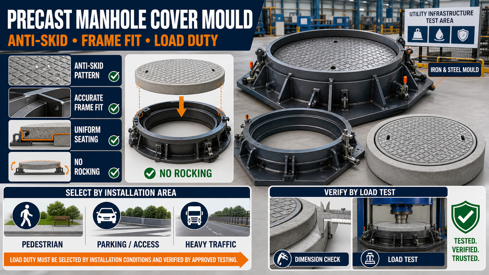
Precast Manhole Cover Mould: Anti-Skid Pattern, Frame Fit and Load-Duty Selection
Precast Manhole Cover Mould: Anti-Skid Pattern, Frame Fit and Load-Duty Selection
Precast concrete manhole covers and frames provide access to underground drainage, sewerage, utility and inspection chambers. Their performance depends on correct structural design, manufacturing quality and accurate compatibility between the cover and its supporting frame.
A heavy-duty iron and steel mould helps reproduce the required shape, dimensions, edge protection, seating surface and anti-skid pattern consistently.
However, the mould alone does not determine the load capacity of the finished cover. Load duty also depends on the approved product design, concrete strength, reinforcement, curing, dimensions and successful load testing.
Paras Steel Industries manufactures precast moulds using iron and heavy-duty steel components. Cover shape, frame profile, anti-skid pattern and production arrangement can be customized according to approved customer drawings.
What Is a Precast Manhole Cover Mould?
A precast manhole cover mould is used to manufacture concrete covers and their matching frames.
A complete manufacturing setup may contain:
• Manhole cover mould • Matching frame mould • Heavy-duty iron or steel casting base • Side shutters • Patterned facing plate • Edge-forming arrangements • Seating-surface formers • Lifting-hole or hook formers • Reinforcement-positioning fixtures • Alignment and locking components • Structural channels and stiffeners
Separate moulds may be needed for the cover and frame because both components have different profiles.
Common Manhole Cover Shapes
Circular Covers
Circular covers are widely used because they cannot fall through a correctly sized circular opening. Their moulds require accurate diameter, roundness and seating geometry.
Square Covers
Square covers may be specified for chambers with square openings. Mould squareness and equal diagonal measurements are important.
Rectangular Covers
Rectangular covers may be used for larger utility chambers or multi-part access systems. The design must provide adequate seating and reinforcement.
Multi-Part Covers
Large openings may use several cover sections supported by an approved frame or intermediate beams. Every component must be produced according to the complete system drawing.
The shape should be selected according to the project specification and chamber design.
Why Is an Anti-Skid Pattern Important?
The top surface of a manhole cover may become wet, dusty or exposed to vehicle movement. An anti-skid pattern improves surface texture and helps provide traction.
Common patterns may include:
• Raised diamond pattern • Chequered pattern • Cross-rib pattern • Circular rib pattern • Grid pattern • Project-specific geometric pattern • Directional groove pattern
The pattern should be functional, manufacturable and easy to demould.
Anti-Skid Pattern Design Considerations
Pattern Depth
A shallow pattern may not create a clearly visible texture. Excessively deep patterns may trap air, collect dirt or cause demoulding problems.
Pattern Spacing
Raised ribs should be distributed consistently across the surface. Irregular spacing can affect appearance and finishing.
Drainage
The pattern should not create unnecessary pockets where water can collect.
Edge Clearance
Anti-skid ribs should maintain suitable clearance from the cover edge, lifting points and identification areas.
Demoulding Direction
The pattern should avoid severe undercuts that can lock the concrete inside the mould.
Wear Allowance
The selected surface design should consider the expected operating environment and permitted wear.
The final pattern must follow the approved drawing and applicable project requirements.
Patterned Steel Facing Plate
The anti-skid texture can be formed through a patterned iron or steel facing plate installed inside the cover mould.
The patterned surface must remain:
• Flat • Clean • Securely fixed • Free from concrete residue • Correctly centred • Undamaged • Properly coated with release agent
Dents, damaged ribs or accumulated concrete can transfer defects to every manufactured cover.
What Is Cover-to-Frame Fit?
Cover-to-frame fit describes how the finished cover sits inside or on its matching supporting frame.
A correctly fitting cover should rest uniformly on the designed seating surface. It should not rock, jam or contain excessive unintended clearance.
Important fit details include:
• Cover outside dimensions • Frame clear opening • Seating width • Seating depth • Edge profile • Permitted clearance • Cover thickness • Frame level • Contact-surface flatness • Lifting clearance
These dimensions should be coordinated between the cover mould and frame mould.
Problems Caused by Poor Frame Fit
Rocking Cover
Uneven seating surfaces can cause the cover to rock when traffic passes over it.
Jammed Cover
Insufficient clearance, dimensional variation or damaged edges may make the cover difficult to remove.
Excessive Gap
Too much clearance may allow movement, debris entry or an unacceptable installation gap.
Uneven Finished Level
Incorrect seating depth may cause the cover to sit above or below the surrounding frame.
Concentrated Loading
If only part of the cover contacts the frame, forces may become concentrated instead of being transferred uniformly.
Cover and Frame Trial Assembly
A trial assembly should be performed during mould development and regular production.
The inspection may include:
1. Place the finished frame on a level surface. 2. Clean its seating area. 3. Lower the matching cover carefully. 4. Check the gap around the perimeter. 5. Inspect the complete bearing contact. 6. Test for rocking. 7. Check the finished level. 8. Verify safe removal using the designed lifting point. 9. Record the dimensions. 10. Correct the mould if repeated fit problems are found.
Covers and frames should be inspected as compatible components.
Understanding Load-Duty Selection
Load duty refers to the loading conditions the cover-and-frame assembly is designed and tested to resist.
The required duty depends on the installation location, expected traffic and applicable standard.
Typical installation conditions include:
• Pedestrian areas • Landscaped areas • Footpaths • Residential access areas • Parking areas • Internal industrial roads • Commercial vehicle routes • Highway or heavy-traffic areas • Industrial loading zones
A cover suitable for a pedestrian area should not automatically be used in a vehicle traffic lane.
Load Duty Is Not Determined by Mould Thickness Alone
A common mistake is assuming that a deeper cover mould automatically produces a heavy-duty cover.
Actual performance depends on:
• Approved structural design • Cover dimensions • Concrete grade and mix design • Reinforcement type and placement • Concrete cover • Frame support • Edge protection • Manufacturing quality • Compaction • Curing • Load testing • Installation quality
Load-duty claims should be supported by testing according to the applicable standard or project specification.
Applicable Standard and Testing
For Indian projects, precast concrete manhole covers and frames may be specified with reference to IS 12592 or another authority-approved requirement.
The manufacturer should confirm:
• Applicable standard and current amendments • Required grade or load duty • Product shape and dimensions • Material requirements • Reinforcement details • Cover-to-frame seating compatibility • Edge protection • Lifting arrangement • Required inspection and load tests • Marking requirements
The project authority’s approved specification takes priority.
Manhole Cover Mould Components
A heavy-duty manhole cover mould may include:
• Iron or steel base plate • Circular, square or rectangular side form • Patterned top-facing plate • Removable edge shutters • Steel edge-protection fixture • Lifting-device former • Reinforcement-positioning guides • Identification-marking plate • Mechanical locking system • Structural stiffeners
The construction should be suitable for the cover dimensions and expected production cycle.
Matching Frame Mould
The frame mould produces the component that supports the cover at the installation opening.
Important frame details include:
• Clear opening • Outer dimensions • Overall depth • Seating ledge • Contact surface • Edge protection • Anchorage or connector details • Reinforcement position • Installation level
The cover and frame mould drawings should be developed together to maintain compatibility.
Reinforcement Placement
Reinforcement must follow the approved structural drawing.
Before casting, check:
• Reinforcement type • Bar or wire diameter • Spacing • Concrete cover • Cage position • Reinforcement around lifting points • Reinforcement near edges • Steel frame or edge components • Secure fixing before vibration
The reinforcement should not touch the mould surface unless the approved design specifically requires an embedded component at that position.
Lifting Arrangements
Manhole covers require a safe method for removal and maintenance access.
Possible arrangements include:
• Lifting holes • Recessed lifting hooks • Embedded lifting components • Approved key-operated recesses
The mould former must reproduce the lifting detail accurately without weakening the finished product.
Production Process
A typical manufacturing cycle includes:
1. Clean the iron or steel mould. 2. Inspect the anti-skid pattern. 3. Check all dimensions and locking points. 4. Apply a thin, uniform layer of release agent. 5. Position the reinforcement correctly. 6. Install lifting and edge components. 7. Close and secure the mould. 8. Pour the approved concrete mix. 9. Compact the concrete uniformly. 10. Finish the required surface. 11. Cure the product according to the approved method. 12. Demould after sufficient strength is achieved. 13. Inspect the pattern, dimensions and edges. 14. Trial-fit the cover with its frame. 15. Conduct specified testing before dispatch.
The cover should not be represented as load-rated until the required testing and approval have been completed.
Quality-Control Checks
Inspect finished products for:
• Shape and overall dimensions • Cover thickness • Frame opening • Roundness or squareness • Anti-skid pattern quality • Seating-surface flatness • Cover-to-frame fit • Rocking • Lifting-point position • Edge damage • Honeycombing • Cracks • Concrete strength • Reinforcement cover • Permanent identification • Required load-test performance
Measurements and test results should be documented according to the applicable quality plan.
Common Production Problems
Incomplete Anti-Skid Pattern
Air trapped around raised or recessed pattern details can produce incomplete surface texture.
Concrete Sticking to the Pattern
Possible causes include poor cleaning, incorrect release-agent application or problematic undercuts.
Cover Does Not Fit the Frame
This may result from mould dimensional errors, distorted shutters, incorrect clearance or damaged seating surfaces.
Cover Rocks Inside the Frame
Uneven seating, frame distortion or concrete residue on contact surfaces can cause rocking.
Damaged Edges
Premature demoulding, poor handling or insufficient mould clearance can break the edges.
Surface Cracks
Cracks may be related to concrete quality, curing, reinforcement, handling or structural design and should be investigated.
Mould Cleaning and Maintenance
After every production cycle:
• Remove concrete residue. • Clean all anti-skid pattern recesses. • Inspect the patterned facing plate. • Check seating-surface formers. • Inspect locking points and shutters. • Verify circularity or squareness. • Examine channels, welds and stiffeners. • Lubricate approved moving components. • Repair slurry-leakage points. • Check lifting-hole formers. • Verify dimensions periodically.
Avoid using cleaning tools that damage the anti-skid pattern or seating surfaces.
Factors to Check Before Buying
Before ordering a precast manhole cover and frame mould, provide:
• Approved cover-and-frame drawing • Circular, square or rectangular shape • Complete dimensions • Required anti-skid pattern • Required load duty • Applicable standard • Reinforcement details • Edge-protection arrangement • Lifting-point design • Required production capacity • Number of mould cavities • Vibration method • Required dimensional tolerance • Testing and marking requirements
A load-duty name alone is not sufficient. The manufacturer requires the complete approved structural and dimensional design.
Conclusion
A precast manhole cover mould should create an accurate anti-skid surface, consistent dimensions and a compatible cover-to-frame seating arrangement.
Load-duty selection must be based on the installation location, structural design and applicable testing requirements. It should never be determined only from mould depth or visual appearance.
Paras Steel Industries manufactures heavy-duty iron and steel precast moulds according to customer drawings and production requirements. Buyers should provide complete cover, frame, reinforcement and load-duty specifications before mould manufacturing begins.