
Precast Mould Guide
Precast Door Frame Mould Corner Bracing: Diagonal Measurement, Twist Control and Rebate Consistency
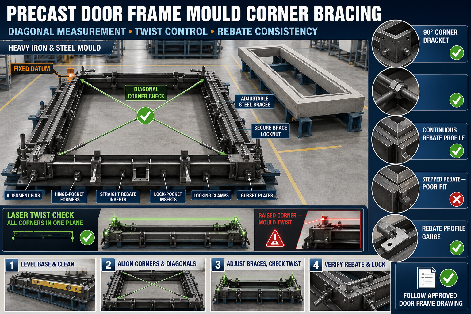
Incorrect corner bracing can make a precast door frame mould rack, twist or produce inconsistent rebates. This guide explains fixed-datum setup, diagonal checks, brace adjustment and pre-casting inspection.
By Paras Steel Industries ·
Precast Door Frame Mould Corner Bracing: Diagonal Measurement, Twist Control and Rebate Consistency
Precast Door Frame Mould Corner Bracing Guide
A precast concrete door frame must maintain accurate corners, straight jambs and a consistent rebate profile so that the door shutter, hinges and locking hardware can fit correctly.
The heavy iron door frame mould forms the two vertical jambs and top member as one controlled frame profile. During concrete placement and vibration, the mould can rack or twist if its corners and supporting braces are not correctly positioned.
Corner bracing helps maintain the intended geometry, but braces should only hold an already aligned mould. They should not be used to force a bent or damaged mould into position.
This guide explains door frame mould corner bracing, including diagonal measurement, 90-degree alignment, twist control and rebate-consistency checks.
What Is Door Frame Mould Corner Bracing?
Corner bracing is the structural arrangement that supports the junction between the door-frame mould jambs and head section.
A typical bracing system may include:
• Heavy iron mould members • Diagonal steel tie bars • Corner brackets • Gusset plates • Adjustable braces • Alignment pins • Bolts • Locknuts • Mechanical clamps • Cross members • Base-frame supports • Fixed corner stops
The exact arrangement should follow the approved door frame drawing.
Why Corner Bracing Is Important
Correct bracing helps maintain:
• Approved corner geometry • Equal diagonal measurements • Straight jambs • Head-member alignment • Mould squareness • Rebate continuity • Hinge-pocket position • Lock-insert position • Consistent frame opening • Easier door installation
A small mould error can create fitment problems at the construction site.
Common Door Frame Mould Problems
Typical problems include:
• Unequal diagonals • One jamb leaning • Head member out of level • Corner angle changing • Mould twisting • Rebate width varying • Rebate step at the corner • Hinge pockets misaligned • Frame opening wider at one end • Locks difficult to engage • Slurry leakage at corners • Concrete edges breaking during demoulding
These issues should be corrected before concrete placement.
Safety Before Mould Setup
Before adjustment:
1. Stop nearby vibration equipment. 2. Place the mould on a firm and level surface. 3. Isolate hydraulic or powered mechanisms where fitted. 4. Apply lockout and tagout where required. 5. Mechanically support movable shutters. 6. Inspect lifting and handling equipment. 7. Clear unnecessary personnel. 8. Keep hands away from brace and clamp pinch points. 9. Wear suitable personal protective equipment. 10. Confirm the mould is empty and stable.
Do not loosen structural braces while the mould contains concrete.
Clean the Mould Before Alignment
Hardened concrete can change the position of corner components.
Clean:
• Corner joints • Base plates • Bracing brackets • Alignment-pin holes • Rebate-forming surfaces • Hinge-pocket inserts • Lock inserts • Shutter flanges • Mechanical stops • Casting surfaces • Seal grooves • Mould supports
Measurements should only be taken after cleaning.
Inspect the Heavy Iron Mould
Check every mould member for:
• Straightness • Bowing • Twisting • Local plate damage • Cracked welds • Bent flanges • Corrosion • Loose stiffeners • Damaged corners • Previous unapproved repairs • Worn alignment points • Distorted lifting points
A bent jamb-forming member should be repaired rather than pulled straight only with a brace.
Inspect Corner Braces
Check braces for:
• Bending • Cracks • Damaged threads • Elongated holes • Loose locknuts • Corrosion • Missing pins • Worn bushes • Weld damage • Incorrect identification • Concrete buildup • Improvised extensions
Use only approved brace components.
Establish a Fixed Datum
A fixed datum provides a repeatable reference for the mould setup.
The datum may be:
• One bottom corner • Mould base centreline • Fixed jamb stop • Head-member reference • Machined locating point • Approved floor or fixture reference
All important measurements should relate to the same datum.
Prepare a Level Base
A mould cannot be accurately squared on a twisted base.
Check:
• Base-frame level • Support contact • Foundation condition • Packing plates • Anchor points • Cross-member position • Concrete buildup underneath • Frame straightness
Do not use loose wood, bricks or random scrap as permanent supports.
Initial Mould Assembly
A suitable setup sequence is:
1. Clean all mould members. 2. Establish the fixed datum. 3. Position the first jamb. 4. Position the opposite jamb. 5. Install the head member. 6. Engage corner alignment pins. 7. Fit all braces loosely. 8. Check the opening dimensions. 9. Compare diagonals. 10. Adjust gradually. 11. Lock the braces. 12. Recheck the complete mould.
Do not fully tighten one corner before assembling the others.
What Is Diagonal Measurement?
Diagonal measurement compares the distances between opposite mould corners.
For a rectangular frame requiring square geometry, matching approved diagonals help indicate that the corners are properly related.
Diagonal measurement should be used together with:
• Corner-square checks • Jamb straightness • Head-member level • Base-frame flatness • Twist checks • Rebate measurements
Equal diagonals alone do not prove that every mould member is straight.
Identify Consistent Reference Points
Use fixed and repeatable measuring points.
Suitable references may include:
• Machined corner marks • Jig pins • Border intersections • Dedicated gauge points • Approved mould marks
Do not measure from damaged edges or movable handles.
Diagonal Checking Procedure
A controlled procedure includes:
1. Clean all reference points. 2. Assemble the mould loosely. 3. Measure the first diagonal. 4. Measure the opposite diagonal. 5. Use the same instrument and tension. 6. Compare the readings. 7. Adjust braces gradually. 8. Recheck opening width and height. 9. Tighten all locks. 10. Measure the diagonals again. 11. Record the result.
The acceptable difference should follow the approved mould drawing.
Do Not Adjust One Brace Excessively
Pulling one corner too far may:
• Bend the mould member • Change opening width • Distort the rebate • Lift the opposite corner • Create twist • Damage brace brackets • Misalign hinge pockets
Use small and balanced adjustments.
Corner Geometry Check
Where the design requires 90-degree corners, inspect using:
• Engineer’s square • Approved corner template • Diagonal measurement • Fixed checking jig • Survey or laser equipment where suitable
Check both the casting profile and outer structural frame.
Corner Bracket Inspection
At each corner, verify:
• Full seating • Alignment-pin engagement • Flange contact • Bolt position • Gusset-plate condition • Internal profile continuity • Rebate transition • Slurry-seal condition • Weld integrity
A gap at the corner may appear as a concrete fin or step.
What Is Mould Twist?
Twist occurs when mould corners do not lie in the intended plane.
A mould can have equal diagonals when viewed from above but still be twisted vertically.
Twist may cause:
• Door frame rocking • Jambs leaning in different directions • Unequal rebate depth • Difficult installation • Door shutter binding • Uneven plaster or wall contact • Corner stress • Demoulding difficulty
Twist checks are essential.
Causes of Mould Twist
Possible causes include:
• Uneven foundation • Incorrect supports • Over-tightened diagonal braces • Bent mould members • Welding distortion • Damaged corner brackets • Unbalanced concrete placement • Excessive vibration • Improper lifting • Thermal variation
Correct the cause before adjusting the braces.
Checking Mould Twist
Use an approved method such as:
• Laser-plane check • String lines across opposite corners • Survey level • Straightedge and level • Fixed setup jig • Height gauges at reference points
Check:
• All four main corners • Jamb bases • Head-member ends • Intermediate support points • Rebate-forming surfaces • Base-frame contact
Compare all readings with the approved setup requirement.
Corner-Height Check
If one corner is high or low:
• Inspect base support • Check for debris • Verify brace tension • Inspect frame distortion • Check adjustment feet • Examine the foundation
Do not force the high corner downward only by tightening a brace.
Diagonal Brace Adjustment
Adjustable braces should be used in a controlled sequence.
A suitable process is:
1. Loosen all brace locknuts slightly. 2. Confirm the base-frame level. 3. Establish the first fixed corner. 4. Bring the opposite corner into position. 5. Adjust the second diagonal gradually. 6. Recheck the opening dimensions. 7. Check the mould plane. 8. Tighten locknuts. 9. Recheck the diagonals. 10. Confirm corner and rebate geometry.
The exact process should follow the mould design.
Brace Contact Points
Braces should connect to reinforced structural areas.
Do not brace against:
• Thin casting plates • Rebate edges • Hinge-pocket formers • Lock inserts • Unreinforced shutters • Hydraulic lines • Lifting handles
Incorrect contact can deform the mould.
Brace Fastener Security
Inspect:
• Bolt specification • Threads • Washers • Locknuts • Pins • Retainers • Welded brackets • Contact faces • Adjustment mechanisms
Tighten fasteners according to the approved procedure and specified torque.
Do not use assumed torque values.
Rebate Profile Function
A door-frame rebate forms the step against which the door shutter closes.
A precast door frame mould may form:
• Single rebate • Double rebate • Project-specific profile • Safety-door provision • Hinge-side details • Lock-side details
The profile must remain consistent around the frame.
Why Rebate Consistency Matters
An inconsistent rebate can cause:
• Door shutter binding • Uneven closing gap • Hinge misalignment • Lock mismatch • Visible corner steps • Difficulty fitting a second door • Site grinding or modification • Poor appearance
Rebate checks should be completed before casting and after demoulding.
Inspect Rebate-Forming Inserts
Check for:
• Straightness • Consistent profile • Corner matching • Secure fastening • Correct orientation • Slurry gaps • Concrete buildup • Damage • Loose ends • Relationship with hinge pockets
A straight outer mould does not guarantee a correct internal rebate.
Rebate Width and Depth Checks
Use an approved profile gauge or template to check:
• Both jambs • Head section • All corners • Hinge locations • Lock location • Intermediate points • Single- or double-rebate transition
Do not rely on one measurement.
Rebate Corner Continuity
At the junction between jamb and head, inspect:
• Profile matching • Internal step • Gap • Corner radius or chamfer • Seal • Insert contact • Fastener position • Concrete-fin risk
The profile should transition according to the approved drawing.
Use a Rebate Profile Template
An approved rigid template helps detect:
• Width variation • Depth variation • Taper • Corner steps • Damaged insert edges • Concrete buildup • Incorrect insert selection
Keep the template labelled and protected.
Hinge-Pocket Alignment
Corner-brace adjustment must not disturb hinge-pocket positions.
Check:
• Pocket centreline • Pocket spacing • Depth • Orientation • Distance from the datum • Relationship with the rebate • Insert fastening • Reinforcement clearance
Use an approved checking jig.
Lock-Pocket and Hardware Inserts
Also verify:
• Lock recess • Striker detail • Embedded plates • Threaded inserts • Door-stop profile • Reinforcement clearance • Orientation • Height
These components should remain aligned with the finished frame geometry.
Reinforcement Cage Placement
The reinforcement cage must fit without pushing the mould out of alignment.
Check:
• Cage centreline • Concrete cover • Corner reinforcement • Jamb bars • Head-member bars • Spacers • Hinge-pocket clearance • Lock-insert clearance • Lifting inserts
Do not use mould braces to counter pressure from a badly positioned reinforcement cage.
Slurry Control at Corners
Cement slurry can escape through corner gaps.
Common leakage locations include:
• Jamb-to-head joints • Rebate corners • Insert joints • Locking points • Modular connections • Damaged seals • Alignment-pin openings
Leakage can create concrete fins that affect door fit.
Inspect Seals and Joint Surfaces
Check for:
• Cuts • Cracks • Flattening • Hardening • Missing seal sections • Concrete buildup • Bent flange edges • Uneven compression • Misaligned corners
Use compatible sealing material according to the mould design.
Mould-Release Agent
Apply a suitable release agent to clean iron casting surfaces and approved reusable inserts.
The release agent should:
• Be compatible with precast concrete • Form a thin uniform film • Avoid pooling in rebates • Avoid reinforcement-bond areas • Cover hinge-pocket formers correctly • Be used according to manufacturer instructions
Excess material can collect in profile corners.
Pre-Casting Inspection Checklist
Before concrete placement, verify:
• Mould identification • Fixed datum • Base-frame level • Opening width and height • Both diagonals • Corner geometry • Twist or corner-height readings • Brace engagement • Rebate width and depth • Rebate corner continuity • Hinge-pocket positions • Lock-pocket positions • Reinforcement cover • Joint sealing • Release-agent application
Record the inspection according to the plant’s quality procedure.
Concrete Placement
Concrete should be placed in a balanced sequence.
During casting:
• Fill both jamb regions progressively • Avoid loading only one corner • Control concrete impact • Monitor braces • Check locks • Maintain reinforcement position • Observe slurry leakage • Stop if the mould shifts
Uneven concrete placement can rack the frame.
Controlled Vibration
During vibration:
• Use the approved equipment • Avoid direct impact on mould inserts • Monitor braces and fasteners • Avoid excessive vibration • Check corner leakage • Observe mould movement • Stop if abnormal noise develops
Vibration should compact concrete without changing mould geometry.
Post-Casting Alignment Check
Where accessible and safe, inspect reference points after concrete placement.
Check:
• Brace position • Locknut movement • Corner displacement • Flange gaps • Slurry leakage • Mould-base movement
Do not adjust loaded structural braces without an approved procedure.
Demoulding Sequence
Begin demoulding only after the concrete reaches the required stripping condition.
A controlled sequence may include:
1. Clean concrete from locks and joints. 2. Support removable shutters. 3. Release non-structural inserts as designed. 4. Release locks gradually. 5. Remove corner restraints in the approved sequence. 6. Move mould members directly away from the concrete. 7. Protect rebate edges. 8. Avoid twisting the finished frame. 9. Lift from approved points. 10. Place the frame on level supports. 11. Inspect dimensions and corners. 12. Clean the mould immediately.
Do not force the frame out while a corner component remains engaged.
Protecting Rebate Edges
Rebate corners are vulnerable during demoulding.
To protect them:
• Confirm adequate stripping condition • Use suitable release agent • Keep forming inserts smooth • Open mould members in the correct direction • Avoid sideways scraping • Use approved protective pads • Control lifting movement • Stop when abnormal resistance occurs
Do not strike the finished rebate with steel tools.
Post-Demoulding Quality Checks
Inspect the finished precast door frame for:
• Opening width • Opening height • Diagonals • Corner geometry • Frame plane • Jamb straightness • Rebate width • Rebate depth • Rebate continuity • Hinge pockets • Lock details • Edge condition • Cracks • Honeycombing • Concrete fins
Acceptance should follow the approved drawing.
Trial Door-Fit Check
Where included in the quality plan, use an approved checking fixture or representative door template.
Check:
• Clear opening • Rebate contact • Hinge alignment • Lock relationship • Head clearance • Jamb parallelism • Binding • Corner fit
This should be a controlled fit check, not forced installation.
Common Setup Problems
Diagonals Are Unequal
Check corner positions, brace adjustment, opening dimensions and base-frame level.
Diagonals Match but Frame Is Twisted
Complete corner-height or laser-plane checks. Equal diagonals alone do not eliminate twist.
One Jamb Is Bowed
Inspect the mould member, intermediate stiffeners, reinforcement pressure and support points.
Rebate Is Deeper at One End
Check insert alignment, mould twist, concrete buildup and fastener sequence.
Rebate Has a Step at the Corner
Inspect the jamb-to-head insert joint and corner-piece seating.
Hinge Pockets Do Not Align
Check the fixed datum, pocket jig and whether brace adjustment displaced the mould member.
Concrete Fin Appears at a Corner
Inspect flange contact, seal condition, locking pressure and concrete buildup.
Brace Repeatedly Loosens
Check threads, locknuts, vibration, bracket wear and mould distortion.
Corner Cracks During Demoulding
Possible causes include early demoulding, rough insert surfaces, incorrect release direction or lifting twist.
Preventive Maintenance Checklist
After Every Casting Cycle
• Clean corner joints • Remove slurry from rebates • Inspect braces • Clean alignment pins • Check locks • Inspect hinge-pocket formers • Clean mould surfaces
Scheduled Checks
• Verify brace straightness • Inspect brackets and welds • Check thread wear • Confirm datum points • Measure mould diagonals • Check mould plane and twist • Inspect rebate profiles • Verify hinge-pocket jigs • Check base-frame level • Replace damaged seals • Record repairs and deviations
When Should Production Be Stopped?
Stop using the door frame mould if you find:
• Cracked corner braces • Bent mould members • Broken alignment pins • Failed locking brackets • Unacceptable diagonal differences • Mould twist • Inconsistent rebate profile • Loose hinge-pocket inserts • Major slurry leakage • Unstable base supports • Repeated corner breakage • Inability to maintain approved dimensions
Production should resume only after repair and a successful empty-mould setup check.
Conclusion
Accurate door frame mould corner bracing begins with a level base, one fixed datum and correctly assembled iron mould members. Diagonal measurements help verify corner relationships, while plane and corner-height checks are required to identify mould twist.
Braces should hold the aligned mould without deforming its jambs or rebate-forming inserts. Rebate width, depth and corner continuity must be checked independently around the complete frame.
Paras Steel Industries manufactures heavy-duty iron and structural-steel precast door frame moulds according to customer requirements and approved drawings. Balanced bracing, documented dimensional checks and controlled demoulding help support straight frames and consistent door fitment.