
Precast Infrastructure Moulds
Precast Bridge Girder Mould Soffit Camber: Datum Setup, Profile Checking and Adjustment Guide
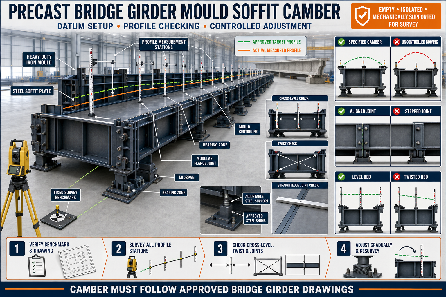
The soffit profile of a precast bridge girder is formed by the mould bed. Incorrect datum levels, support settlement or uneven adjustment can change the specified camber and girder geometry. This guide explains survey setup, profile checking and controlled alignment of a heavy-duty iron bridge girder mould.
By Paras Steel Industries ·
Precast Bridge Girder Mould Soffit Camber: Datum Setup, Profile Checking and Adjustment Guide
Precast Bridge Girder Mould Soffit Camber: Datum Setup, Profile Checking and Adjustment Guide
A precast bridge girder mould must reproduce the geometry specified in the approved girder drawings. One important part of this geometry is the soffit profile formed by the mould bed.
The soffit is the underside of the finished girder. Depending on the engineered design, its mould profile may include specified camber, straight sections, end transitions or other controlled geometry.
Incorrect survey datums, foundation movement, support settlement or unplanned mould adjustment can change this profile. Regular inspection is therefore essential before reinforcement placement and concrete casting.
What Is a Bridge Girder Soffit?
The soffit is the bottom surface of a precast bridge girder.
In the mould, this surface is formed by:
• Main soffit plate • Mould-bed segments • Modular extension sections • End transitions • Bearing-zone formers • Adjustable steel supports • Structural beams and stiffeners
The finished profile should follow the approved girder and mould drawings.
What Is Soffit Camber?
Camber is a specified upward profile incorporated into the girder geometry or mould setup according to the engineered design.
It may account for factors considered by the bridge designer, but the mould manufacturer and precast producer should not assume or calculate camber without approved engineering information.
The mould should reproduce the specified profile accurately and repeatably.
Camber Is Not the Same as Uncontrolled Bowing
Specified Camber
Specified camber is an intentional profile shown in the approved drawing.
Uncontrolled Bowing
Bowing is an unintended deformation caused by:
• Support movement • Mould distortion • Welding heat • Foundation settlement • Incorrect adjustment • Uneven loading • Structural damage
An apparent curve in the mould should never automatically be treated as approved camber.
Why Soffit-Camber Accuracy Is Important
Correct mould-bed geometry supports:
• Approved girder profile • Consistent girder depth • Correct bearing-zone relationship • Accurate end geometry • Reliable reinforcement cover • Better dimensional repeatability • Controlled site installation • Reduced product rejection • Consistent production records
Final acceptance should always follow the project quality plan.
Heavy-Duty Iron Bridge Girder Mould Construction
A bridge girder mould may include:
• Heavy steel soffit plate • Structural H-beams • C-channel or box-section stiffeners • Side shutters • End shutters • Modular extension sections • Flanged joints • Slurry-sealing surfaces • Adjustable supports • Base plates • Foundation anchors • Hydraulic or mechanical opening systems • Bearing-zone formers • Lifting and handling points
The complete structure must support the required mould profile.
Common Causes of Soffit-Profile Error
Profile variation may result from:
• Incorrect initial setup • Survey benchmark error • Foundation settlement • Loose anchor bolts • Uneven adjustable supports • Damaged steel shims • Distorted soffit plate • Loose modular joints • Mismatched extension sections • Cracked welds • Bent stiffeners • Thermal movement • Impact during handling • Previous repair distortion • Concrete buildup below a joint • Uncontrolled adjustment
The source of the error should be identified before correction.
What Is a Survey Datum?
A survey datum is a verified reference point or reference elevation used for all mould-profile measurements.
A reliable datum should be:
• Stable • Clearly identified • Protected from damage • Independent of movable mould components • Suitable for repeated surveys • Related to the approved project control system
The factory floor should not be assumed to be level or stable enough to act as the primary datum.
Types of Useful Reference Points
A profile survey may use:
• Permanent foundation benchmark • Verified survey marker • Mould centreline • Fixed base-frame points • End reference points • Approved modular-joint locations • Bearing-centre references • Defined measurement stations
All points should be clearly recorded.
Why Datum Setup Must Be Verified
An incorrect benchmark can make every mould reading appear wrong.
Before beginning:
• Verify the benchmark identity • Check survey-equipment calibration • Confirm units and drawing revision • Check the required profile reference • Confirm measurement direction • Identify mould start and end points • Record environmental conditions where required • Confirm the mould is empty and stable
Do not adjust the mould until the datum has been verified.
Preparing the Mould for Profile Checking
Before inspection:
• Complete safe demoulding • Remove the finished girder • Clean the soffit surface • Remove concrete and slurry • Isolate hydraulic equipment • Release stored pressure • Mechanically support side shutters • Remove unnecessary loads • Inspect the foundation • Verify modular joints • Review the approved profile drawing • Establish a safe survey route
The mould should be checked in the defined reference condition.
Mould Condition During Survey
Readings may change depending on whether:
• Side shutters are open or closed • End shutters are installed • Reinforcement is present • The mould is empty • Hydraulic cylinders are pressurised • Temporary platforms are installed • Sunlight heats one side • Nearby vibration equipment is operating
The inspection condition should be consistent and recorded.
Establishing the Mould Centreline
The bridge girder mould centreline helps control:
• Longitudinal profile • Modular alignment • Side-shutter position • Bearing-former location • End geometry • Survey stations
Transfer the approved centreline to stable points on the mould frame or foundation.
Creating Profile Measurement Stations
The soffit should be checked at defined stations along its length.
Possible station locations include:
• Both ends • Bearing zones • Modular flange joints • Support points • Midspan • Intermediate locations • Areas with previous repair • Locations showing visible distortion
The station spacing should follow the approved inspection plan.
Tools for Soffit-Profile Measurement
Suitable equipment may include:
• Digital level • Optical level • Total station • Laser level • Survey staff • Calibrated straightedge • Feeler gauges • Dial indicator • Approved profile template
The selected method should provide the accuracy required by the project.
Checking the Longitudinal Soffit Profile
A general survey procedure may include:
1. Verify the Benchmark
Confirm the fixed survey datum.
2. Mark Measurement Stations
Identify all required locations.
3. Clean Each Measurement Point
Remove material that could affect the reading.
4. Set Up the Survey Equipment
Position it on a stable surface.
5. Take Initial Datum Reading
Record the reference elevation.
6. Measure Every Soffit Station
Use the same point location and method.
7. Record the Actual Profile
Enter all readings in sequence.
8. Compare With the Approved Profile
Identify high and low locations.
9. Repeat Critical Readings
Confirm unusual results.
10. Record the Mould Condition
Note shutter position and environmental factors.
No generic camber value should be assumed.
Checking Cross-Level
The mould should also be checked across its width.
Cross-level readings can identify:
• Soffit plate roll • One side higher than the other • Twisted mould bed • Unequal support adjustment • Side-beam settlement • Local distortion
Take corresponding left, centre and right readings at selected stations.
Checking Mould-Bed Twist
Twist occurs when the cross-level relationship changes along the mould length.
Twist may affect:
• Girder geometry • Web alignment • Reinforcement cover • Side-shutter contact • End-shutter fit • Bearing regions
Use longitudinal and cross-level data together to identify twist.
Checking Local Flatness
The overall profile can be correct while the soffit plate contains local high or low spots.
Inspect using:
• Verified straightedge • Feeler gauge • Local survey grid • Dial-indicator fixture • Approved template
Pay attention to:
• Welded joints • Flange connections • Support locations • Previous repair areas • Bearing-zone transitions • Plate edges
Checking Modular Extension Joints
Modular bridge girder mould sections should connect without a step.
Inspect each flange joint for:
• Vertical alignment • Horizontal alignment • Joint gap • Bolt condition • Complete flange contact • Slurry-sealing condition • Plate-surface continuity • Stiffener alignment • Support position
A small step at a modular joint may be reproduced on every girder.
Profile Continuity Across Joints
Use a straightedge, survey reading or approved template across each joint.
Check for:
• Sudden high point • Sudden low point • Angular break • Side offset • Local twist • Raised seal material • Concrete trapped between flanges
Correct the joint rather than grinding the finished girder repeatedly.
Checking End and Bearing Zones
End zones may contain:
• Bearing-seat details • End blocks • Diaphragm formers • Chamfers • Recesses • Project-specific inserts
Confirm that soffit camber transitions correctly into these areas.
Do not adjust an end zone independently without reviewing its relationship with the complete profile.
Inspecting Adjustable Supports
Adjustable steel supports may be used to set the mould elevation.
Inspect:
• Support position • Thread condition • Lock nuts • Bearing contact • Base plate • Steel shims • Welded brackets • Corrosion • Movement marks • Full load path
A support should not carry load through only one edge.
Inspecting Steel Shims
Approved steel shims may assist with controlled levelling.
Check that shims are:
• Correctly located • Flat • Fully supported • Free from debris • Stable • Protected from displacement • Recorded in the setup plan • Not stacked unpredictably
Wood, broken tiles and loose scrap should not be used as permanent packing.
Inspecting the Foundation
Foundation movement can alter the soffit profile.
Look for:
• Concrete cracks • Settlement • Gaps below base plates • Loose anchors • Damaged grout • Water entry • Poor drainage • Soil movement • Repeated support adjustment • Changes in benchmark readings
Foundation problems should be evaluated by appropriately qualified personnel.
Inspecting the Iron Mould Structure
Check the structural frame for:
• Bent H-beams • Twisted channels • Cracked welds • Loose flange connections • Damaged base plates • Local plate buckling • Distorted stiffeners • Previous repair marks • Impact damage • Corrosion at concealed joints
A profile error cannot always be corrected through support adjustment alone.
Thermal Effects on a Long Mould
A long steel mould can change dimension and profile with temperature.
Uneven heating may occur because of:
• Direct sunlight • Hot curing systems • Nearby welding • One-sided heat exposure • Different inspection times • Hot concrete • Cold-water cleaning
Where required by the inspection procedure, record temperature and perform surveys under comparable conditions.
Do Not Adjust From One Reading
An unusual reading may result from:
• Dirty measurement point • Survey-staff movement • Instrument disturbance • Incorrect station • Wrong benchmark • Recording error • Temporary load • Temperature variation
Repeat and verify the measurement before changing the mould.
Planning a Soffit-Profile Adjustment
Before adjustment:
• Confirm the approved target profile • Verify the benchmark • Review all measurement data • Identify high and low stations • Check cross-level and twist • Inspect supports and foundation • Review modular joints • Identify fixed and adjustable points • Prepare an adjustment sequence • Mechanically support the mould • Establish an exclusion zone • Use qualified personnel
Adjustment should be controlled and documented.
Controlled Adjustment Procedure
The exact method depends on the mould design. A general sequence may include:
1. Isolate and Secure the Mould
Prevent shutter or hydraulic movement.
2. Record Baseline Readings
Complete the full profile survey.
3. Identify the Root Cause
Determine whether the issue is support, foundation, joint or structural distortion.
4. Release Approved Connections
Loosen only the specified anchors or locks.
5. Support the Mould at Designed Points
Use properly rated equipment.
6. Adjust in Small Stages
Avoid a large change at one location.
7. Recheck Nearby Stations
Every adjustment can affect adjacent areas.
8. Check Cross-Level and Twist
Do not focus only on longitudinal camber.
9. Secure Supports and Anchors
Follow the approved sequence and specifications.
10. Complete a Final Survey
Record the finished profile and mould condition.
Never use uncontrolled force to bend the mould into position.
Adjusting Modular Sections
When correcting extension sections:
• Clean flange faces • Support both modules • Align the soffit plates • Check the centreline • Tighten flange connections progressively • Control the slurry-seal joint • Recheck profile stations on both sides • Verify stiffener continuity • Inspect end-shutter position
A joint should not be pulled into alignment only through bolt force.
Repairing a Distorted Soffit Plate
Local plate distortion may require an approved repair plan.
Before repair:
• Measure the damaged area • Inspect supporting stiffeners • Identify the cause • Review forming-surface requirements • Control heat input • Protect surrounding geometry • Recheck after cooling • Conduct a full profile survey • Perform a trial assembly where required
Uncontrolled heating or welding can create additional distortion.
Side-Shutter Relationship With the Soffit
Side shutters must meet the soffit plate accurately.
Inspect:
• Lower side-shutter joint • Profile transition • Locking points • Joint gaps • Slurry seals • Web position • Shutter straightness • Hydraulic movement
Changing the soffit elevation may affect side-shutter closure.
End-Shutter Relationship With the Soffit
After any adjustment, confirm:
• End-shutter squareness • Girder length • Soffit transition • End-block details • Joint sealing • Lock engagement • Insert position • Bearing-former relationship
The complete mould should be treated as one geometric system.
Reinforcement and Soffit Profile
Reinforcement supports should follow the approved girder drawing and mould profile.
Check:
• Bottom cover • Support-chair height • Cage centreline • End-zone reinforcement • Bearing-zone reinforcement • Prestressing arrangement where applicable and engineered • Insert clearance • Stability during concrete placement
Do not change reinforcement supports to compensate for an incorrect mould bed.
Pre-Pour Profile Checklist
Before installing reinforcement or casting, confirm:
• Correct drawing revision is available • Survey benchmark is verified • Mould centreline is marked • Longitudinal profile is checked • Cross-level is checked • Twist is within approved requirements • Modular joints are aligned • Bearing zones are verified • Supports are secure • Anchors are stable • Side shutters close correctly • End shutters are aligned • Soffit surface is clean • Release agent is uniformly applied • Survey record is approved
No production should begin from an unverified profile.
Monitoring During Concrete Casting
During casting, observe the mould safely for:
• Support movement • Anchor movement • Joint leakage • Side-shutter displacement • Unusual structural noise • Local plate movement • Hydraulic changes • Concrete pressure effects
Do not enter hazardous zones to take measurements during casting unless the approved procedure specifically provides a safe method.
Post-Casting and Post-Demoulding Checks
After production, compare:
• Mould profile records • Finished girder dimensions • Soffit surface • End geometry • Bearing regions • Web alignment • Visible joint marks • Product survey results where required
Recurring product deviations may indicate progressive mould movement.
Troubleshooting Common Problems
Problem: Midspan Profile Is Too Low
Possible causes:
• Central support settlement • Incorrect support adjustment • Foundation movement • Soffit beam deflection • Wrong datum or profile calculation
Problem: Midspan Profile Is Too High
Possible causes:
• Excessive support adjustment • Wrong drawing revision • Incorrect benchmark • Steel shim buildup • Local structural distortion
Problem: Profile Changes Suddenly at a Modular Joint
Possible causes:
• Flange faces are dirty • Modules are at different elevations • Joint bolts are tightened unevenly • One module is unsupported • Soffit plates are mismatched
Problem: One Side of the Mould Is Higher
Possible causes:
• Unequal base supports • Foundation settlement • Twisted structural frame • Cross-level adjustment error • Local base-plate gap
Problem: Profile Changes Between Inspections
Possible causes:
• Loose anchors • Support movement • Temperature variation • Foundation settlement • Nearby vibration • Inconsistent mould condition during survey
Problem: Finished Girder Soffit Has a Local Step
Possible causes:
• Modular-joint mismatch • Damaged soffit plate • Concrete buildup • Raised seal material • Previous weld repair • Local plate buckling
Inspection Records
Maintain records of:
• Survey date • Mould identification • Girder type • Drawing revision • Benchmark • Equipment used • Mould condition • Measurement stations • Actual readings • Adjustments • Final verification • Inspector approval
Historical data helps identify gradual settlement or structural change.
Soffit Mould Maintenance Checklist
After each production cycle:
• Clean the soffit plate • Remove slurry from joints • Inspect modular flanges • Check support contact • Inspect anchors • Examine welds and stiffeners • Check adjustable supports • Inspect steel shims • Check side-shutter joints • Inspect end transitions • Protect forming surfaces • Record visible movement or damage • Schedule profile surveys according to the quality plan
Do not allow concrete to harden beneath modular joints or support points.
Benefits of Accurate Soffit-Camber Setup
Correct setup provides:
• Approved girder geometry • Repeatable soffit profile • Better modular-joint continuity • Controlled cross-level • Reduced local steps • Improved reinforcement-cover control • More reliable end geometry • Lower rejection and repair • Better production traceability • Longer mould service life
Conclusion
The soffit profile of a precast bridge girder is established by the heavy-duty iron mould bed and its supporting structure. Specified camber should always come from approved engineering drawings and should not be confused with uncontrolled mould bowing.
A reliable inspection requires a verified survey datum, clearly marked stations and measurements of the longitudinal profile, cross-level, twist, modular joints and bearing zones. Any adjustment should be gradual, documented and performed only after identifying the root cause.
An accurately aligned bridge girder mould helps precast manufacturers reproduce the required soffit geometry consistently across major infrastructure production.