
Precast Mould Guide
New Jersey vs F-Shape Highway Barrier Mould: Profile and Application Comparison
New Jersey and F-shape barriers have similar concrete safety profiles, but their slope transition points and performance characteristics differ. This guide compares their profiles, applications and heavy-duty iron and steel mould requirements.
By Paras Steel Industries ·
New Jersey vs F-Shape Highway Barrier Mould: Profile and Application Comparison
New Jersey vs F-Shape Highway Barrier Mould: Profile and Application Comparison
New Jersey and F-shape concrete barriers are widely used for highway medians, road-diversion projects, construction zones, bridge approaches and roadside protection.
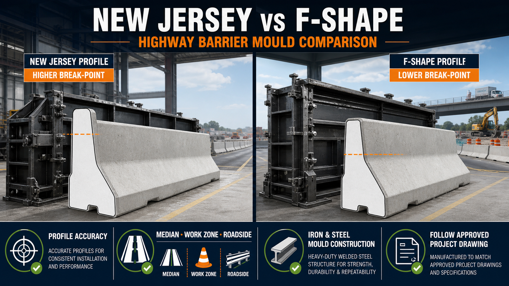
Although both are safety-shape barriers, they do not have identical profiles. Their lower-slope transition or break-point differs, which affects the mould geometry and the barrier’s interaction with an impacting vehicle.
Therefore, a New Jersey barrier mould and an F-shape barrier mould should be manufactured according to the exact approved project drawing. One profile should not be substituted for another without approval from the responsible highway authority or project engineer.
Paras Steel Industries manufactures precast moulds using iron and heavy-duty steel components. Barrier length, profile, plate thickness, connection openings and operating system can be customized according to the buyer’s approved drawing and production requirements.
What Is a New Jersey Barrier?
A New Jersey barrier is a concrete safety barrier featuring a narrow upper section, sloping sides and a wider base.
Its lower section begins with a short vertical face near the road surface. This is followed by a lower sloping face that transitions into a steeper upper face.
The profile is designed to redirect an impacting vehicle while helping prevent it from crossing into an opposing traffic lane, work zone or protected roadside area.
New Jersey barriers may be manufactured as portable precast units or installed as permanent barriers, depending on the approved project design.
What Is an F-Shape Barrier?
An F-shape barrier is also a concrete safety-shape barrier. Its overall appearance is similar to the New Jersey profile, but the transition between the lower and upper slopes is positioned lower.
According to FHWA guidance, both profiles begin with a short vertical face. The New Jersey profile has a higher slope break-point, while the F-shape profile uses a lower break-point.
The F-shape was developed to reduce vehicle climb and rollover potential during certain impacts. However, actual barrier selection must be based on the applicable road authority’s approved and crash-tested design.
Main Profile Difference
The most important difference is the height at which the lower sloping section meets the steeper upper section.
New Jersey Profile
• Higher transition or break-point • Longer lower sloping face • Traditional and widely recognized barrier shape • Must follow the approved New Jersey barrier drawing
F-Shape Profile
• Lower transition or break-point • Shorter lower sloping face • Designed to limit vehicle climb in severe impacts • Must follow the approved F-shape barrier drawing
The mould manufacturer should receive a complete cross-sectional drawing. Manufacturing the mould only from a product photograph can lead to incorrect angles and dimensions.
New Jersey vs F-Shape Comparison
Profile Geometry
The New Jersey barrier has a higher lower-slope transition. The F-shape uses a lower transition while retaining a similar safety-shape appearance.
Vehicle Interaction
The F-shape was developed to reduce vehicle climb and improve post-impact behaviour in certain conditions. This does not mean that every F-shape barrier is automatically suitable for every road.
Applications
Both profiles may be used for highway medians, temporary traffic control, roadside protection and infrastructure projects when permitted by the responsible authority.
Project Approval
The required barrier profile, reinforcement, connection system and installation arrangement must match the approved project specification.
Mould Requirements
Both profiles require accurate iron or steel shutters, strong reinforcement, reliable locking and precise slope geometry.
Applications of New Jersey Barriers
New Jersey barriers may be used for:
• Highway median separation • Temporary road-diversion work • Construction-zone protection • Traffic-lane separation • Bridge and approach projects • Roadside hazard protection • Industrial traffic management • Restricted-area separation
The permitted application depends on the approved barrier design, connection system, anchorage and crash-test classification.
Applications of F-Shape Barriers
F-shape barriers may be specified for:
• Highway and expressway medians • Temporary work-zone protection • Roadside safety projects • Bridge approaches • Lane-separation projects • High-traffic infrastructure corridors • Permanent or portable barrier systems
Final selection should be made by the project designer or highway authority.
Why Accurate Mould Geometry Matters
Highway barriers are safety-related products. Small errors in the mould profile can affect the finished dimensions and compatibility with the approved design.
Important mould measurements include:
• Overall barrier height • Base width • Top width • Vertical reveal • Lower-slope angle • Upper-slope angle • Transition-point height • Product length • End-face geometry • Connection and lifting openings
All dimensions should be taken from an approved technical drawing.
Iron and Steel Mould Construction
A highway barrier mould normally requires a strong base frame and reinforced shutters because fresh concrete applies substantial pressure during filling and vibration.
A heavy-duty mould may include:
• Iron or steel base frame • Profile-shaped side shutters • Removable end plates • Structural channels and angles • Uniformly positioned stiffeners • Alignment rods • Mechanical or hydraulic locking systems • Connection-hole formers • Lifting-slot formers • Vibration-compatible supports
Plate thickness and stiffener spacing should be selected according to the barrier dimensions, concrete pressure and required number of production cycles.
One standard plate thickness should not be assumed for every highway barrier mould.
Fixed vs Opening Barrier Mould
Fixed-Base Mould
A fixed-base system may use opening side shutters with a permanent casting bed or mould base.
Possible benefits include:
• Strong structural support • Consistent alignment • Suitability for repeated production • Easier integration with vibration systems
Opening or Hydraulic Mould
Heavy shutters can be operated through mechanical locks or hydraulic cylinders.
A hydraulic system may reduce manual effort and changeover time. However, it requires trained operators and regular inspection of hoses, seals, fittings and cylinders.
Connection Openings and End Details
Portable precast barriers normally require an approved connection system between adjacent units. The mould may therefore need accurately positioned formers for:
• Pin-and-loop connections • Steel connector slots • Bolt openings • Lifting holes • Anchorage openings • End recesses • Drainage openings
These details must match the tested or approved barrier system. Connection components should not be changed without engineering approval.
Reinforcement Placement
The reinforcement cage should be manufactured according to the approved structural drawing.
Before casting, check:
• Reinforcement-bar diameter and spacing • Concrete cover • Cage alignment • Position of connection hardware • Lifting inserts • Anchorage components • Clearance from mould shutters • Reinforcement near openings and ends
The reinforcement cage must not move during concrete filling or vibration.
Production Process
A typical highway barrier manufacturing cycle includes:
1. Clean the iron or steel mould completely. 2. Inspect the profile shutters and locking points. 3. Apply a suitable mould-release agent. 4. Position the reinforcement cage. 5. Install approved connection and lifting components. 6. Close and align the shutters. 7. Verify the complete barrier profile. 8. Pour concrete uniformly. 9. Compact the concrete using the approved vibration method. 10. Finish the exposed concrete surface. 11. Cure the barrier according to the approved procedure. 12. Demould only after sufficient concrete strength is achieved. 13. Inspect the dimensions and surface quality. 14. Move the barrier using approved lifting points.
Quality-Control Checks
Every production batch should be inspected for:
• Correct barrier profile • Overall dimensions • Transition-point position • Straightness • End-face squareness • Concrete surface finish • Honeycombing • Cracks and damaged edges • Connection alignment • Lifting-point position • Reinforcement cover • Concrete strength
Templates or profile gauges can help verify the finished cross-section.
Common Mould Problems
Incorrect Profile
This may occur when the mould is manufactured from an incomplete drawing or the shutters become distorted.
Slurry Leakage
Loose joints and damaged seals can allow cement slurry to escape, resulting in poor edges and surface defects.
Shutter Bulging
Insufficient stiffeners or uneven locking may allow the shutter to move under concrete pressure.
Connection Misalignment
Poorly positioned formers can create difficulty when adjoining barrier sections are installed.
Difficult Demoulding
Concrete residue, inadequate release agent, damaged shutters or premature demoulding can cause sticking and edge damage.
Maintenance Requirements
After every casting cycle:
• Remove concrete residue. • Clean shutter joints and contact surfaces. • Inspect clamps, bolts and locking points. • Check profile shutters for distortion. • Inspect channels, angles and welds. • Lubricate approved moving parts. • Clean connection-hole formers. • Repair slurry-leakage points. • Verify profile accuracy periodically. • Inspect hydraulic components where installed.
Do not use uncontrolled hammering to release the concrete because it can damage the mould and finished barrier.
Which Barrier Mould Should You Select?
Choose a New Jersey barrier mould when the approved project drawing specifies a New Jersey safety-shape profile.
Choose an F-shape barrier mould when the project specification requires the lower transition geometry of an approved F-shape barrier.
The decision should not be based only on mould price or visual similarity. Verify:
• Highway authority requirements • Approved cross-sectional profile • Applicable crash-test standard • Barrier height and length • Connection and anchorage system • Temporary or permanent application • Required production capacity • Available factory equipment
Never describe an untested product as a crash-tested barrier simply because its shape appears similar to an approved design.
Buying Checklist
Before ordering, share the following details with the mould manufacturer:
• Approved barrier drawing • New Jersey or F-shape profile • Overall dimensions • Product length • Required number of cavities • Reinforcement details • Connection-system drawing • Lifting and anchorage openings • Manual or hydraulic operation • Vibration method • Expected daily production • Required dimensional tolerance • Factory layout and handling system
Conclusion
New Jersey and F-shape highway barriers have similar appearances, but their lower-slope transition geometry differs. The F-shape uses a lower break-point intended to reduce vehicle climb during certain impacts.
Both mould types require accurate profile geometry, strong iron or steel construction, reliable locking and regular maintenance.
Paras Steel Industries manufactures heavy-duty iron and steel precast moulds according to customer drawings and production requirements. Buyers should provide an approved highway-barrier design before mould engineering and manufacturing begin.