
Precast Mould Guide
Manhole Cover Mould Lifting-Hook Insert Setup: Jig Alignment, Concrete Cover and Position Checks
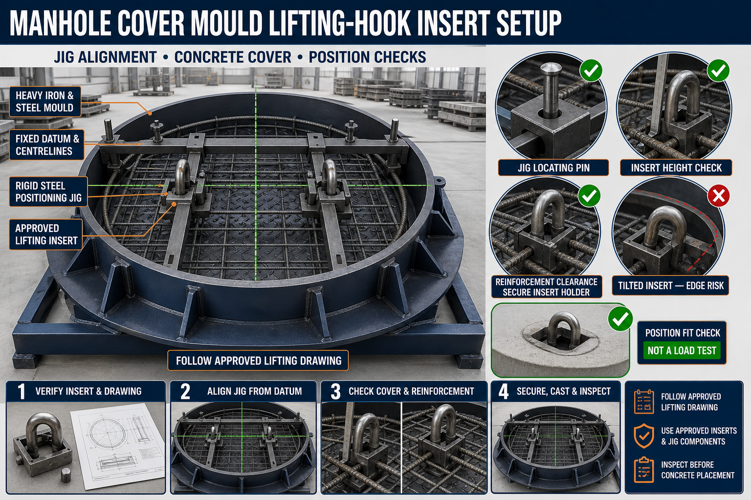
Incorrectly positioned lifting-hook inserts can make a precast manhole cover difficult or unsafe to handle. This guide explains jig alignment, insert restraint, concrete cover, reinforcement clearance and post-casting position checks.
By Paras Steel Industries ·
Manhole Cover Mould Lifting-Hook Insert Setup: Jig Alignment, Concrete Cover and Position Checks
Manhole Cover Mould Lifting-Hook Insert Setup Guide
Precast concrete manhole covers may contain lifting hooks, lifting eyes or other approved handling inserts. These components allow the cured cover to be lifted, positioned and removed using suitable handling equipment.
The insert must remain accurately positioned during reinforcement placement, concrete filling and vibration. If it tilts, moves or sits too close to a concrete edge, the finished cover may not meet its approved handling requirements.
A dedicated positioning jig can hold the insert at the required centreline, height and orientation while concrete is placed.
This guide explains manhole cover mould lifting hook insert setup, including jig alignment, concrete cover, reinforcement clearance and final position checks.
Important Engineering Requirement
Lifting inserts are safety-critical components.
Their type, material, embedment, orientation, reinforcement arrangement and working load must be specified through an approved lifting design.
Do not select or position an insert only from general practice.
Always follow:
• Approved product drawing • Structural design • Lifting plan • Insert manufacturer’s instructions • Project quality requirements • Applicable safety procedures
This guide focuses on mould setup and production inspection, not lifting-system design.
What Is a Manhole Cover Lifting-Hook Insert?
A lifting-hook insert is a steel component cast into a precast manhole cover to provide a designated handling point.
Depending on the approved design, it may include:
• Steel lifting hook • Lifting eye • Threaded lifting insert • Embedded loop • Recess former • Anchor plate • Reinforcing tail • Cross bar • Additional local reinforcement • Removable lifting attachment
Only inserts approved for the specific cover design should be used.
What Is an Insert Positioning Jig?
A positioning jig is an iron or structural-steel fixture that holds the lifting insert in its required location during casting.
A jig may include:
• Mould-mounted support bar • Centreline reference • Insert holder • Locating pin • Adjustable bracket • Height stop • Orientation plate • Locking nut • Spacer • Recess former • Quick-release mechanism • Identification mark
The jig should be rigid enough to prevent insert movement during concrete placement and vibration.
Why Insert Position Is Important
Correct positioning helps:
• Maintain the approved lifting point • Keep handling forces balanced • Maintain required concrete cover • Avoid edge breakout risk • Prevent reinforcement interference • Keep the lifting attachment accessible • Maintain cover appearance • Support repeatable production • Reduce site-handling problems • Make inspection easier
An insert that appears only slightly displaced may still affect safe handling.
Types of Manhole Cover Moulds
Lifting inserts may be used in:
• Circular manhole covers • Square covers • Rectangular covers • Cover-and-frame mould sets • Light-, medium- or heavy-duty designs • Custom utility covers • Drainage access covers • Electrical or communication chamber covers
The insert arrangement must match the approved cover type.
Safety Before Jig Setup
Before preparing the mould:
1. Stop nearby vibration equipment. 2. Isolate powered mould mechanisms. 3. Place the mould on a stable surface. 4. Clean the work area. 5. Inspect the insert and jig. 6. Remove damaged components. 7. Wear suitable personal protective equipment. 8. Keep hands away from clamp pinch points. 9. Use safe handling methods for heavy mould parts. 10. Follow the approved production drawing.
Do not begin casting with an incomplete or improvised jig.
Inspect the Heavy Iron Mould
Before insert setup, inspect the manhole cover mould.
Check:
• Mould base • Outer border • Inner frame-forming section • Tapered side walls • Anti-skid pattern plate • Locking points • Hinges • Stiffeners • Base-frame level • Casting-surface cleanliness • Mould centreline • Jig mounting points
The mould must be dimensionally stable before setting insert positions.
Clean the Mould
Remove:
• Hardened concrete • Cement slurry • Old release-agent buildup • Rust flakes • Dirt • Aggregate particles • Material inside jig holes • Debris around pattern plates • Concrete from border joints
Contamination can change the jig position or insert height.
Verify the Approved Drawing
Before installation, confirm:
• Cover type • Insert type • Number of inserts • Insert spacing • Centreline position • Orientation • Embedment arrangement • Required recess • Reinforcement relationship • Concrete cover • Lifting direction
Do not rely only on a previous batch or visual memory.
Insert Identification
Each insert should be identified and checked before use.
Verify:
• Correct component type • Material and certification where required • Product identification • Condition • Thread type where applicable • Approved lifting attachment • Recess-former compatibility • Reinforcement-tail configuration • Corrosion condition • Batch traceability where required
Do not use an unknown insert.
Inspect the Lifting Insert
Check for:
• Bending • Cracks • Damaged threads • Corrosion • Weld defects • Deformed loops • Damaged anchor plates • Missing components • Concrete contamination from previous use • Unapproved modification
A damaged insert should be rejected according to the quality procedure.
Do Not Weld or Modify Inserts Without Approval
Unapproved welding, heating, bending or grinding can change the insert’s properties and performance.
Avoid:
• Welding additional rods directly to the insert • Heating and reshaping • Enlarging holes • Cutting anchor tails • Grinding load-bearing areas • Using random substitute hooks
Use only the approved insert configuration.
Establish the Mould Centreline
Mark or identify:
• Longitudinal centreline • Transverse centreline • Geometric centre • Fixed datum • Insert axes • Jig reference points • Cover orientation
These references should remain visible during setup.
Fixed-Datum Positioning
Position the jig from one fixed mould datum instead of measuring from movable borders or previous inserts.
A suitable datum may be:
• Mould centre • Fixed border reference • Machined stop • Alignment pin • Base-frame mark • Pattern-plate reference
Use the same datum for every production cycle.
Check Jig Straightness
Before installation, inspect the jig for:
• Bending • Twisting • Cracked welds • Loose brackets • Worn locating pins • Enlarged holes • Damaged threads • Corrosion • Concrete buildup • Previous repairs
A bent jig can misposition every insert in the batch.
Mounting the Jig
A controlled setup may include:
1. Clean the mould mounting points. 2. Establish the fixed datum. 3. Position the jig. 4. Engage locating pins. 5. Install bolts or clamps loosely. 6. Align the jig centreline. 7. Check height references. 8. Tighten fasteners gradually. 9. Recheck alignment. 10. Confirm the jig cannot move.
Do not force a misaligned jig into position.
Jig Alignment Checks
Check the jig for:
• Centreline alignment • Squareness • Level • Height • Distance from mould edges • Relationship with reinforcement • Position relative to the pattern plate • Insert-holder orientation • Clearance for concrete placement
Use approved measuring tools or templates.
Insert Centreline Position
For symmetrical lifting arrangements, insert centrelines should match the approved layout.
Check:
• Distance from mould centre • Spacing between inserts • Relationship with cover edges • Alignment with lifting direction • Orientation relative to the frame • Position around circular covers
Do not assume all covers use symmetrical lifting points.
Insert Height and Embedment
The jig should hold the insert at the approved vertical position.
Incorrect height may cause:
• Insufficient embedment • Excessive recess • Exposed steel • Reduced concrete cover • Difficulty attaching lifting equipment • Interference with reinforcement • Surface-finishing problems
Use an approved height gauge or template.
Concrete Cover Around the Insert
Concrete cover protects embedded steel and helps maintain the designed concrete zone around the lifting point.
Check cover relative to:
• Top surface • Bottom surface • Outer edge • Recess • Anti-skid pattern • Frame seating area • Nearby openings • Reinforcement cage
Required cover should follow the structural drawing.
Do Not Guess Concrete Cover
The required cover depends on:
• Cover design • Exposure condition • Insert type • Concrete strength • Reinforcement arrangement • Edge distance • Lifting design • Applicable project requirements
Use only the approved value.
Use Cover Gauges and Spacers
Approved spacers or checking gauges can help maintain insert position.
They should:
• Match the drawing • Remain stable during vibration • Be compatible with concrete • Avoid visible surface defects • Not interfere with reinforcement • Not shift the jig • Be stored and inspected correctly
Do not use loose scrap pieces as permanent spacers.
Reinforcement Clearance
The lifting insert must work with the approved reinforcement arrangement.
Check:
• Main reinforcement position • Local insert reinforcement • Additional bars • Link arrangement • Concrete cover • Clearance around the insert • Recess-former position • Connection with the anchor plate • Cage stability
Do not cut or bend reinforcement at the mould without engineering approval.
Local Reinforcement Around the Insert
Some lifting systems require additional reinforcement around the insert.
This may include:
• Hairpin bars • Cross bars • U-bars • Links • Edge reinforcement • Anchorage reinforcement • Project-specific details
The exact arrangement must follow the approved lifting design.
Jig-to-Reinforcement Interference
The jig should hold the insert without pushing the reinforcement cage out of position.
Inspect for:
• Jig touching main bars • Insert tails displacing links • Reduced concrete cover • Cage lifting • Recess former contacting reinforcement • Fasteners obstructing concrete flow
Correct the setup before casting.
Insert Orientation
Some lifting inserts have a defined load direction or attachment orientation.
Confirm:
• Loop direction • Thread orientation • Recess alignment • Anchor-plate position • Lifting direction • Top and bottom • Left and right where applicable • Relationship with the panel centreline
Incorrect orientation can make the lifting attachment difficult or unsafe to use.
Recess-Former Setup
A recess former creates access around certain lifting inserts.
Check:
• Correct former type • Insert compatibility • Centre alignment • Seating • Fastening • Sealing • Release-agent application • Removal direction • Concrete cover • Reinforcement clearance
The recess former should not float or move during vibration.
Threaded Insert Protection
Where threaded inserts are used:
• Install the approved thread protector • Prevent concrete entry • Keep threads clean • Confirm full engagement • Protect the opening during finishing • Remove protectors only through the approved process • Inspect threads after demoulding
Do not clean damaged threads using unapproved cutting methods.
Secure the Insert Against Movement
The insert should remain restrained in all necessary directions.
The jig may need to control:
• Sideways movement • Rotation • Vertical movement • Tilting • Floating • Movement during vibration
The restraint should hold the insert without damaging it.
Insert Locking Check
Before casting, confirm:
• Holder engagement • Locking nut • Retaining clip • Jig clamp • Height stop • Orientation stop • Recess-former connection • Fastener security
Mark inspected points where required.
Mould-Release Agent
Apply a suitable mould-release agent to the iron mould and approved reusable jig surfaces.
Keep release agent away from:
• Required concrete-bond surfaces • Insert anchor areas • Reinforcement • Threads unless specifically allowed • Embedded plates requiring bond
Follow the release-agent manufacturer’s instructions.
Pre-Casting Position Checklist
Before concrete placement, verify:
• Correct mould and cover type • Insert identification • Number of inserts • Jig position • Fixed-datum reference • Insert centreline • Spacing • Orientation • Height • Concrete cover • Reinforcement clearance • Local reinforcement • Recess-former position • Thread protection • Holder and retainer security
Record the inspection before authorising casting.
Independent Position Verification
For safety-critical inserts, a second authorised person should verify the setup according to the quality plan.
The check may include:
• Drawing comparison • Jig identification • Position measurement • Insert type • Reinforcement • Concrete cover • Retaining components • Documentation
Do not rely only on the installer’s visual check.
Concrete Placement Around Inserts
Concrete should be placed carefully around the jig and insert.
During casting:
• Avoid direct heavy impact • Fill progressively • Prevent aggregate bridging • Monitor insert movement • Maintain cage position • Keep the recess former secure • Observe the jig • Stop if movement occurs
The insert must not tilt during filling.
Compaction Around the Insert
Concrete must compact around the insert and local reinforcement without leaving voids.
During vibration:
• Use the approved vibration method • Avoid direct vibrator contact with the insert • Do not strike the jig • Monitor insert position • Avoid excessive vibration • Check reinforcement movement • Observe the recess former • Stop if the jig loosens
Insufficient compaction can create voids, while excessive vibration can move the insert.
Signs of Insert Movement During Casting
Warning signs include:
• Jig shaking excessively • Insert tilting • Height-stop movement • Locking nut loosening • Recess former lifting • Reinforcement displacement • Concrete leaking through the holder • Centreline mark changing
Stop casting and follow the approved corrective procedure.
Do Not Reposition an Insert Blindly in Fresh Concrete
If an insert moves:
• Stop concrete placement • Identify the actual position • Follow the quality-control procedure • Remove concrete where authorised • Restore reinforcement and cover • Reinspect the complete setup • Record the incident
Do not push the insert back by visual judgement alone.
Jig Removal Timing
Remove the jig or holder only when the concrete can retain the insert position and recess shape.
Timing depends on:
• Concrete mix • Temperature • Curing • Jig design • Recess former • Surface condition • Approved production procedure
Do not use one fixed removal time for every batch.
Controlled Jig Release
A suitable release sequence may include:
1. Confirm production approval. 2. Remove concrete from exposed fasteners. 3. Support removable jig parts. 4. Release holders gradually. 5. Withdraw locating pins straight. 6. Avoid moving the embedded insert. 7. Remove the jig in its designed direction. 8. Protect the concrete surface. 9. Inspect insert position. 10. Clean the jig immediately.
Do not use heavy hammering near the lifting insert.
Demoulding the Manhole Cover
Before demoulding:
• Confirm stripping strength • Release mould borders • Inspect the lifting inserts • Check the concrete around each insert • Use only the approved lifting attachments • Confirm the lifting plan • Connect all required points • Clear personnel from the lifting area
Do not use an insert for lifting before its approved handling condition has been reached.
Never Perform an Unapproved Proof Test
Do not test lifting inserts by applying random loads.
Any proof or load testing must follow:
• Approved procedure • Engineering requirement • Calibrated equipment • Safe exclusion zone • Documented acceptance criteria
Visual appearance alone does not confirm lifting capacity.
Post-Demoulding Position Checks
After demoulding, inspect:
• Insert centreline • Insert spacing • Orientation • Recess shape • Accessibility • Concrete cover where verifiable • Concrete around the insert • Cracks • Honeycombing • Exposed reinforcement • Thread condition • Surface damage
Compare the insert location with the approved drawing.
Check Concrete Around the Insert
Reject or hold the cover for engineering assessment if you find:
• Cracks from the insert • Honeycombing • Large voids • Loose concrete • Exposed anchor components • Insert movement • Damaged recess • Insufficient edge distance • Insert tilt • Incorrect reinforcement position
Do not repair safety-critical lifting zones without approval.
Insert Accessibility Check
The lifting attachment should connect without interference.
Check:
• Recess clearance • Thread access • Loop opening • Concrete fins • Pattern-plate interference • Edge clearance • Correct attachment engagement
Do not enlarge the recess through uncontrolled chipping.
Trial Attachment Check
Where the quality plan permits, use the approved lifting attachment to confirm:
• Correct fit • Full engagement • Orientation • Clearance • Thread condition • Removal
This is a fit check, not an unapproved load test.
Common Setup Problems
Insert Tilts During Vibration
Check holder rigidity, jig fasteners, concrete placement and reinforcement interference.
Insert Is Too Close to the Edge
Recheck the datum, jig location, mould identification and drawing.
Insert Height Is Incorrect
Inspect the height stop, spacer, jig bending and concrete buildup beneath the fixture.
Recess Former Moves
Check the former connection, insert compatibility and vibration procedure.
Concrete Enters the Thread
Inspect thread protector installation and sealing.
Jig Does Not Align With the Mould
Check mould type, jig identification, locating pins, concrete buildup and mould distortion.
Concrete Cracks Around the Insert
Hold the product and investigate insert position, reinforcement, concrete quality, compaction and handling.
Insert Is Not Accessible
Check recess depth, former position, concrete fins and insert orientation.
Two Inserts Are Not Symmetrical
Verify that symmetry is actually required, then inspect jig centrelines and fixed-datum positioning.
Preventive Jig Maintenance
After every casting cycle:
• Clean concrete residue • Inspect insert holders • Clean locating pins • Check height stops • Inspect fasteners • Remove hardened slurry • Protect steel surfaces from corrosion
Scheduled checks should include:
• Jig straightness • Centreline verification • Holder wear • Locating-hole wear • Weld inspection • Fastener replacement • Template comparison • Identification and traceability checks
Store jigs on stable, labelled supports.
When Should Production Be Stopped?
Stop using the manhole cover mould setup if you find:
• Incorrect insert type • Damaged lifting inserts • Bent positioning jig • Broken locating pins • Unsecured insert holders • Incorrect concrete cover • Reinforcement interference • Insert movement during casting • Damaged recess formers • Cracks around the insert • Honeycombing in the lifting zone • Inability to verify insert position
Production should resume only after correction and inspection approval.
Quality-Control Record
Maintain records of:
• Cover identification • Mould number • Insert type and batch • Jig identification • Insert positions • Reinforcement inspection • Concrete cover checks • Casting date • Concrete batch • Demoulding inspection • Non-conformities • Corrective actions
Traceability is especially important for embedded lifting components.
Conclusion
Accurate manhole cover mould lifting hook insert setup requires an approved lifting design, a rigid positioning jig and consistent measurement from a fixed mould datum.
Insert centreline, height, orientation, concrete cover and reinforcement clearance must be verified before casting. The jig should restrain the insert against tilting or floating during concrete placement and vibration.
Paras Steel Industries manufactures heavy-duty iron and structural-steel manhole cover moulds according to customer requirements and approved drawings. A correctly designed jig and documented insert inspection process help support consistent handling-point positions and safer precast production.