
Precast Infrastructure Moulds
Manhole Cover Frame Mould Seating-Rim Accuracy: Rocking, Flatness and Fit Inspection Guide
The seating rim determines how evenly a precast manhole cover rests inside its matching frame. Mould distortion, concrete fins or uneven contact surfaces can cause rocking, noise and poor fit. This guide explains seating-rim alignment, flatness checks and cover-to-frame inspection for heavy-duty iron manhole cover mould sets.
By Paras Steel Industries ·
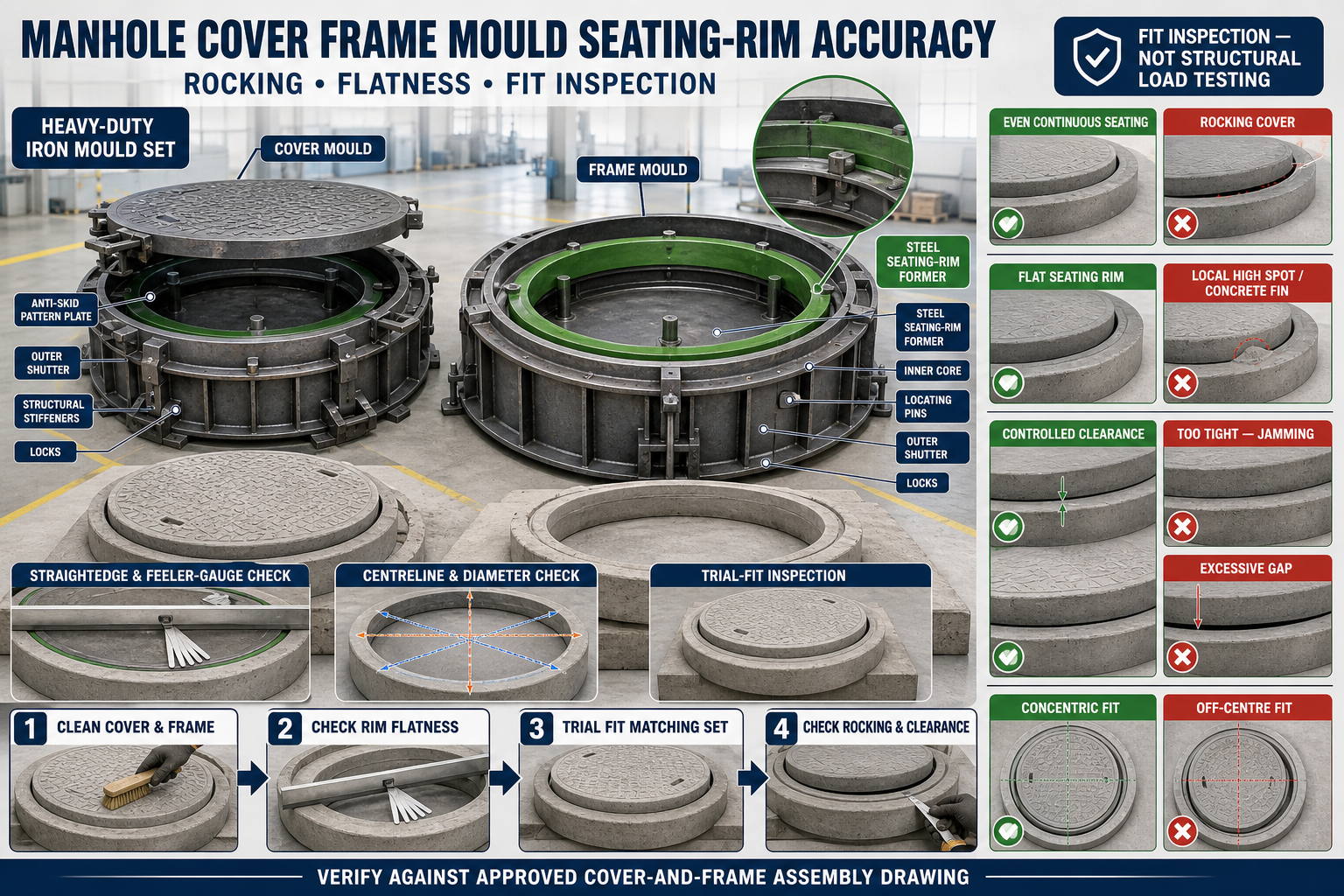
Manhole Cover Frame Mould Seating-Rim Accuracy: Rocking, Flatness and Fit Inspection Guide
Manhole Cover Frame Mould Seating-Rim Accuracy: Rocking, Flatness and Fit Inspection Guide
A precast manhole cover and frame operate as a matching assembly. The cover should sit correctly on the supporting rim of its corresponding frame without uncontrolled rocking or interference.
The seating rim is formed by accurately positioned components inside the heavy-duty iron frame mould. If these components become distorted, worn, dirty or misaligned, the finished frame may not support the cover evenly.
Regular seating-rim inspection helps manufacturers identify mould-related fit problems before products reach the project site.
What Is a Manhole Cover Frame?
A precast manhole frame is the supporting concrete component installed around the manhole opening. It provides the seating surface for the removable cover.
Depending on the approved design, the frame may be:
• Circular • Square • Rectangular • Project-specific in shape • Manufactured as a separate component • Produced as part of a matching cover-and-frame set
Its dimensions and performance requirements should follow the approved product drawing and applicable project specification.
What Is a Seating Rim?
The seating rim is the supporting surface on which the manhole cover rests.
A seating rim may include:
• Continuous bearing ledge • Recessed cover seat • Locating shoulder • Inner frame profile • Contact ring • Project-specific seating detail
The rim should provide the approved contact condition without obstructing cover installation or removal.
What Is Seating-Rim Accuracy?
Seating-rim accuracy refers to the dimensional and geometric condition of the complete cover-supporting surface.
Important factors include:
• Flatness • Level consistency • Profile continuity • Correct internal opening • Cover-to-frame clearance • Concentricity • Squareness where applicable • Surface finish • Absence of concrete fins • Compatibility with the matching cover
A frame can have the correct overall size while still containing a locally uneven seating rim.
Why Seating-Rim Accuracy Is Important
A correctly formed seating rim helps provide:
• Stable cover seating • Even contact • Reduced rocking • Controlled cover-to-frame clearance • Easier installation • Easier approved removal • Reduced edge damage • Consistent top alignment • Lower repair and rejection • Improved assembly quality
The seating rim alone does not establish the complete load duty of the product. Load classification depends on the engineered product design, reinforcement, concrete, manufacturing quality and required testing.
What Is Manhole Cover Rocking?
Rocking occurs when the cover does not rest evenly on the frame and moves between high contact points.
Possible symptoms include:
• One cover edge lifts when the opposite edge is pressed • Visible movement during fit inspection • Uneven contact around the frame • Repeated impact or noise during use • Local gaps beneath the cover • Difficulty achieving a consistent top level
Rocking should be investigated rather than corrected using random packing.
Common Causes of Cover Rocking
Cover rocking may result from:
• Uneven frame seating rim • Warped cover • Concrete fins • Hardened slurry on the mould profile • Mould distortion • Incorrect cover-to-frame pairing • Debris on the seating surface • Damaged cover edge • Uneven concrete finishing • Incorrect demoulding • Inconsistent reinforcement support • Local mould wear
Both the cover and frame should be checked before identifying the defective component.
Heavy-Duty Iron Cover and Frame Mould Set
A typical mould set may include:
• Cover mould • Frame mould • Steel casting plates • Outer shutters • Inner-core former • Seating-rim forming ring • Anti-skid pattern plate where specified • Chamfer strips • Quick locks • Locating pins • Structural stiffeners • Reinforcement-positioning fixtures • Insert fixtures where approved
The cover and frame moulds should be designed as a matching system.
How the Frame Mould Forms the Seating Rim
The seating rim may be created using:
• Machined steel forming ring • Fabricated steel profile • Removable rim insert • Inner-core shoulder • Bolted profile plate • Project-specific forming component
This component must remain flat, centred and securely fixed during concrete casting and vibration.
Preparing the Frame Mould for Inspection
Before checking the rim-forming components:
• Remove the finished frame • Clean the complete mould • Open removable shutters • Isolate powered equipment • Mechanically secure moving components • Remove concrete and slurry • Inspect the inner core • Clean the rim-forming profile • Review the product drawing • Identify verified mould datums
Measurements taken over dirt or concrete deposits will not represent the true mould condition.
Cleaning the Seating-Rim Former
Pay particular attention to:
• Horizontal bearing surface • Inner locating profile • Profile corners • Joint transitions • Bolt recesses • Removable-ring seats • Contact with the outer shutter • Areas near locking points
A thin hardened deposit can create a high point on the finished concrete rim.
Inspecting the Rim-Forming Component
Check the steel former for:
• Bending • Local high or low areas • Cracked welds • Loose bolts • Worn profile edges • Concrete buildup • Corrosion • Impact marks • Joint gaps • Previous repair distortion • Incomplete seating
The forming surface should remain continuous according to the approved design.
Establishing a Fixed Inspection Datum
Use a verified mould reference to check the rim-forming component.
Possible datums include:
• Mould-bed surface • Frame-mould centreline • Machined base-frame point • Fixed outer-shutter reference • Approved locating stop • Survey reference where required
Do not use a loose inner component as the only datum.
Checking Seating-Rim Flatness
A practical flatness inspection may use:
• Verified straightedge • Feeler gauges • Dial indicator • Surface plate or inspection table • Laser-level arrangement • Approved profile gauge
Check the rim:
• Across multiple diameters on a circular frame • Along both diagonals on a square frame • Along all four sides • Between locating points • Near joints • Around the complete circumference
No tolerance should be assumed without consulting the approved drawing.
Checking Circular Seating Rims
For a circular frame mould, inspect:
• Centre position • Ring diameter • Concentricity • Complete circumference • Local high and low areas • Joint continuity • Ring-to-core position • Uniform locking
A forming ring can remain circular but still be tilted relative to the mould bed.
Checking Square or Rectangular Seating Rims
For square or rectangular frames, inspect:
• Side lengths • Corner squareness • Diagonal measurements • Opposite-side parallelism • Rim width • Corner transitions • Flatness along all sides • Inner opening dimensions
Corner distortion can prevent the matching cover from seating correctly.
Checking Rim Level
Rim level describes the elevation relationship around the seating surface.
Check:
• Opposite sides • All corners • Several points around circular frames • Relationship with the mould base • Position after final locking
A level difference may indicate a tilted inner core or unevenly seated profile ring.
Checking Cover Mould Flatness
The frame is only one half of the assembly. Inspect the cover mould as well.
Check:
• Cover underside forming surface • Perimeter seating face • Casting-bed flatness • Edge profile • Anti-skid plate mounting where specified • Mould support • Reinforcement spacers • Concrete buildup • Shutter alignment
A flat frame cannot correct a warped cover.
Cover-to-Frame Clearance
Clearance is the designed space between the cover and frame locating profiles.
Insufficient clearance may cause:
• Cover jamming • Difficult installation • Edge damage • Forced fitting • Difficulty during removal • Interference from minor concrete fins
Excessive clearance may cause:
• Side movement • Poor visual fit • Irregular joint gaps • Uncontrolled positioning • Increased rocking in some geometries
The required clearance should come from the approved cover-and-frame assembly drawing.
Checking Cover-to-Frame Fit
A controlled trial fit should use a verified matching cover and frame.
Inspect:
• Cover enters without uncontrolled force • Seating faces make the intended contact • Clearance is consistent • Cover is correctly centred • Top surfaces align as specified • Cover can be removed using the approved method • No concrete fin causes interference • No visible damage occurs during fitting
Do not force a mismatched cover into the frame.
Using a Master Gauge or Inspection Fixture
A verified inspection fixture can help determine whether the cover or frame is outside the required geometry.
Possible fixtures include:
• Master seating ring • Cover-profile gauge • Frame-opening gauge • Flat inspection plate • Rocking-test fixture • Project-specific template
Inspection fixtures should be protected from wear and checked periodically.
Simple Rocking Inspection
A controlled rocking check can be conducted on a stable inspection surface.
A general method includes:
1. Clean the Cover and Frame
Remove all debris and concrete particles.
2. Place the Frame on a Verified Support
Ensure the frame itself is adequately supported.
3. Install the Matching Cover
Lower it using the approved handling method.
4. Check Contact
Observe whether the intended seating surfaces meet.
5. Apply Controlled Inspection Pressure
Check opposite areas without creating unsafe loading.
6. Observe Movement
Look for lifting, rocking or local gaps.
7. Mark Contact Points
Use the approved inspection method.
8. Record the Result
Identify whether the issue appears related to the cover, frame or both.
This is a fit inspection and does not replace structural load testing.
Using Contact-Marking Methods
An approved removable marking medium may help identify high and low contact areas.
The process may show:
• Continuous bearing • Isolated high spots • Missing contact zones • Local concrete fins • Cover distortion • Frame-rim variation
The marking method should not contaminate the product or hide defects.
Concrete Fins on the Seating Rim
Concrete fins can form when slurry enters gaps in the mould’s rim-forming joints.
Fins may cause:
• Local high spots • Cover rocking • Restricted clearance • Chipped edges • Difficult installation • Extra grinding
Repeated fins should be corrected at the mould joint.
Preventing Slurry Leakage Around the Rim Former
Before casting:
• Clean contact surfaces • Seat removable inserts correctly • Inspect seals • Tighten locks progressively • Check forming-ring joints • Inspect inner-core alignment • Confirm no reinforcement obstructs closure • Check for visible gaps • Monitor the joint during vibration
Do not use excessive seal thickness that changes the seating profile.
Applying Release Agent
Apply a suitable release agent to clean forming surfaces.
Ensure:
• Thin, uniform application • Coverage of the rim profile • No excessive pooling • No contamination of reinforcement • No blockage of small details • Compatibility with the required finish
Uneven application can contribute to difficult demoulding and edge damage.
Reinforcement Placement
Reinforcement should follow the approved structural drawing.
Before casting, verify:
• Correct cage or mesh • Required concrete cover • Stable spacers • Clearance from rim former • Correct position around approved lifting details • No tie wire trapped in joints • Cage cannot move during concrete placement
Do not reduce reinforcement to simplify mould closure.
Concrete Placement Around the Seating Rim
Place concrete carefully around the rim-forming profile.
Good practices include:
• Filling evenly • Avoiding segregation • Preventing aggregate bridging • Keeping reinforcement stable • Avoiding direct impact on removable profiles • Monitoring for leakage • Maintaining approved concrete consistency
The complete rim should receive adequate concrete.
Concrete Compaction
Poor compaction can create voids around the seating rim, while excessive vibration can increase leakage.
During compaction:
• Use the approved vibration method • Monitor locks and inserts • Avoid direct impact on forming components • Check for slurry leakage • Prevent reinforcement movement • Follow the approved duration and sequence
Surface appearance alone does not confirm adequate internal compaction.
Preparing for Demoulding
Before opening the mould:
• Confirm adequate concrete strength • Support the cover or frame • Isolate powered systems • Mechanically secure shutters • Clean concrete around locks • Identify the approved opening sequence • Keep personnel clear of pinch points • Prepare suitable handling equipment
Premature demoulding can damage the seating rim.
Correct Frame Demoulding Sequence
A general sequence may include:
1. Release Outer-Shutter Locks
Open connections progressively.
2. Support Removable Components
Prevent heavy iron shutters from dropping.
3. Separate Outer Shutters
Create controlled clearance.
4. Release the Inner Core
Use the designed removal direction.
5. Protect the Seating Rim
Avoid dragging the former across concrete edges.
6. Lift or Move the Frame Safely
Support it at approved locations.
7. Inspect the Seating Surface
Check for chips, fins and incomplete areas.
8. Clean the Mould Immediately
Remove fresh slurry before it hardens.
Never force the inner core through a concrete fin or undercut.
Post-Demoulding Frame Inspection
Inspect the frame for:
• Seating-rim continuity • Flatness • Internal opening dimensions • Concentricity or squareness • Concrete fins • Chips • Cracks • Honeycombing • Surface finish • Insert position • Compatibility with the cover
Record defects by mould location.
Troubleshooting Common Fit Problems
Problem: Cover Rocks in the Frame
Possible causes:
• Frame rim has a high point • Cover underside is warped • Concrete fin is present • Debris remains on the seat • Mould profile is distorted • Cover and frame are mismatched
Problem: Cover Jams During Installation
Possible causes:
• Clearance is insufficient • Cover dimension is incorrect • Frame opening is distorted • Concrete fin obstructs the profile • Cover is inserted at an angle • Wrong cover type is selected
Problem: Gap Is Larger on One Side
Possible causes:
• Cover is off-centre • Frame opening is out of square • Circular ring is not concentric • Cover perimeter is distorted • Seating shoulder is misaligned
Problem: Frame Rim Is Chipped
Possible causes:
• Concrete strength was insufficient • Inner core was removed at an angle • Release agent coverage was poor • Concrete fin locked the former • Frame was inadequately supported
Problem: Honeycombing Appears Near the Rim
Possible causes:
• Poor concrete placement • Inadequate compaction • Reinforcement congestion • Aggregate bridging • Slurry leakage
Problem: Finished Frame Is Twisted
Possible causes:
• Mould bed is not flat • Inner core is tilted • Shutters are locked unevenly • Frame was supported incorrectly during curing • Mould structure is distorted
Corrective Finishing
Minor fins may be removed through an approved finishing process after the concrete has sufficient strength.
Before corrective work:
• Confirm the defect is superficial • Inspect for cracking • Protect the seating geometry • Avoid changing required dimensions • Record the defect location • Correct the mould before the next pour
Repeated grinding should not replace forming-ring maintenance.
Mould Maintenance Checklist
After every casting cycle:
• Clean the seating-rim former • Clean the cover seating-face mould • Remove slurry from joints • Inspect profile rings • Check inner-core alignment • Inspect locating pins • Check locks and hinges • Examine welds and stiffeners • Inspect seals • Check mould-bed flatness • Clean anti-skid plates where applicable • Lubricate approved moving points • Apply corrosion protection during storage • Record recurring fit problems
Cover and frame moulds should remain identified as a matching set.
Pre-Pour Inspection Checklist
Before concrete placement, confirm:
• Correct cover and frame designs are selected • Moulds are clean • Seating-rim former is fully seated • Profile continuity is checked • Inner core is centred • Rim level is verified • Cover mould is flat • Shutters are square • Joint gaps are controlled • Locks are progressively tightened • Reinforcement follows the drawing • Release agent is uniformly applied • Approved inserts are secure • No tools remain inside the mould
Benefits of Accurate Seating-Rim Production
Accurate mould setup provides:
• Stable cover seating • Reduced rocking • Consistent cover-to-frame clearance • Easier trial fitting • Cleaner seating surfaces • Reduced concrete fins • Lower edge-damage risk • Less grinding and repair • Improved product interchangeability where specified • More reliable installation quality
Conclusion
A precast manhole cover and frame must be treated as a matching assembly. The frame’s seating rim and the cover’s supporting face should both remain flat, dimensionally accurate and free from concrete fins.
Manufacturers should inspect the iron rim-forming components, inner core, cover mould bed, locating points and locking system before every casting cycle. Finished products should undergo a controlled cover-to-frame trial fit and rocking inspection using clean, verified supports.
A well-maintained heavy-duty iron manhole cover and frame mould set helps produce accurate concrete components with stable seating, controlled clearance and reduced fit-related rejection.