
Precast Mould Guide
Highway Barrier Mould Wedge Lock Maintenance: Clamping Pressure, Wear and Slurry Leakage Guide
Worn or unevenly adjusted wedge locks can leave gaps in a highway barrier mould and cause slurry leakage, concrete fins or difficult demoulding. This guide explains lock inspection, balanced clamping, wear diagnosis and maintenance.
By Paras Steel Industries ·
Highway Barrier Mould Wedge Lock Maintenance: Clamping Pressure, Wear and Slurry Leakage Guide
Highway Barrier Mould Wedge Lock Maintenance Guide
Precast highway barrier moulds use heavy side shutters to form New Jersey, F-shape and other approved concrete barrier profiles. These shutters must close tightly and remain stable during concrete placement and vibration.
A mechanical wedge lock converts the operator’s applied force into clamping action at the mould flange. When the wedge, guide, pin or contact plate becomes worn, the lock may not pull the shutter into its correct position.
Insufficient clamping can cause slurry leakage and concrete fins. Excessive or uneven clamping can distort the shutter, damage the seal and make demoulding difficult.
This guide explains highway barrier mould wedge lock maintenance, including wear inspection, balanced clamping pressure, lubrication, adjustment and slurry-leakage diagnosis.
What Is a Highway Barrier Mould Wedge Lock?
A wedge lock is a mechanical locking arrangement used to secure the side shutters of a heavy-duty iron highway barrier mould.
A typical assembly may include:
• Steel wedge • Wedge guide • Locking pin • Striker or catch plate • Lock bracket • Handle • Pivot pin • Washer or spacer • Retaining component • Welded support • Flange-contact surface • Gasket or sealing strip
The exact design should follow the approved mould drawing.
How Does a Wedge Lock Work?
As the wedge moves through its guide, its tapered shape pulls the shutter flange toward the fixed mould section. The lock should create sufficient and repeatable clamping force to close the joint and compress the seal evenly.
The wedge lock should:
• Engage smoothly • Pull the flange into alignment • Maintain joint contact • Compress the seal evenly • Resist vibration • Remain secure during casting • Release without excessive force • Avoid deforming the shutter
The lock should not be used to correct a badly misaligned mould.
Why Wedge Lock Maintenance Is Important
A mould may contain several wedge locks along its length. All of them must work together.
Regular maintenance helps:
• Maintain uniform flange closure • Control slurry leakage • Reduce concrete fins • Protect mould seals • Prevent lock seizure • Reduce shutter distortion • Improve demoulding • Maintain barrier dimensions • Support consistent surface finish • Reduce unexpected production stoppages
One badly worn lock can affect the joint near its position even when other locks appear secure.
Signs of Wedge Lock Problems
Common warning signs include:
• Wedge requires heavy hammering • Lock becomes loose during vibration • Handle movement increases • Wedge does not seat fully • Flange gap remains after locking • Seal compression is unequal • Slurry leaks near one lock • Concrete fins appear repeatedly • Wedge surface has grooves or burrs • Guide plate is bent • Locking bracket is cracked • Shutter is difficult to release • Retaining pin repeatedly loosens
These signs should be investigated before the next casting cycle.
Safety Before Lock Maintenance
Wedge locks restrain heavy iron shutters. Releasing them without supporting the shutter can cause sudden movement.
Before inspection:
1. Stop production. 2. Remove the concrete element where applicable. 3. Position the mould on a stable base. 4. Isolate hydraulic or powered systems. 5. Apply the plant’s lockout and tagout procedure. 6. Release stored pressure through the approved method. 7. Mechanically support the side shutter. 8. Keep personnel away from pinch points. 9. Use appropriate personal protective equipment. 10. Remove locks only after confirming shutter stability.
Never stand between an unsupported shutter and the mould.
Clean the Locking Area
Hardened slurry can prevent complete wedge engagement and hide wear.
Clean:
• Wedge surface • Wedge guide • Pivot pin • Catch plate • Lock bracket • Flange edge • Gasket groove • Retaining components • Welded support • Surrounding shutter surface
Use non-damaging tools and remove concrete before it becomes fully hardened.
Initial Visual Inspection
Inspect every wedge lock along the mould.
Look for:
• Bent wedges • Rounded taper surfaces • Cracks • Burrs • Grooves • Corrosion • Elongated holes • Worn pins • Loose retainers • Bent guides • Cracked welds • Deformed brackets • Uneven contact marks • Previous unapproved repairs
Mark defective locks so they are not missed during repair.
Inspect the Wedge
The wedge’s tapered working surfaces must remain straight and smooth enough to travel through the guide correctly.
Check for:
• Uneven polishing • Flat spots • Mushroomed ends • Hammer damage • Deep scoring • Bent condition • Surface cracks • Loss of taper profile • Rust • Slurry contamination
A severely damaged wedge should be replaced with an approved matching component.
Do Not Repair a Wedge by Guesswork
Grinding the wedge excessively can change its taper and reduce its locking action.
Avoid:
• Uncontrolled grinding • Welding onto the taper • Heating and bending • Using an unrelated replacement wedge • Shortening the wedge • Enlarging guide openings • Adding random packing pieces
Repairs should restore the approved lock geometry.
Inspect the Wedge Guide
The guide controls wedge movement and transfers clamping force into the lock bracket.
Check:
• Guide alignment • Internal wear • Cracks • Bent side plates • Enlarged opening • Welded connection • Concrete buildup • Contact with the wedge • Excessive sideways clearance • Corrosion
A misaligned guide can make a good wedge bind or apply force unevenly.
Inspect Pins and Pivot Points
Pins allow handles and locking components to move.
Check pins for:
• Diameter wear • Grooves • Bending • Cracks • Rust • Missing retainers • Excessive movement • Damaged holes • Poor lubrication • Concrete contamination
Replace worn pins and bushes with approved components.
Inspect the Locking Bracket
The bracket transfers clamping force into the heavy iron shutter and mould frame.
Check:
• Weld cracks • Plate bending • Hole elongation • Corrosion • Shutter connection • Flange alignment • Contact position • Previous repair quality • Loose bolts where applicable
A cracked or distorted bracket requires qualified repair before casting.
Check Shutter and Flange Alignment First
Wedge locks should only hold an already aligned shutter closed. They should not pull a twisted or sagging shutter into place.
Before lock adjustment, inspect:
• Base-frame level • Shutter straightness • Hinge condition • Mechanical stops • Alignment pins • Flange cleanliness • Modular joints • Seal seating • Shutter support • Barrier-profile inserts
Correct structural and alignment problems before adjusting the locks.
What Is Balanced Clamping Pressure?
Balanced clamping means that all locks apply enough force to maintain joint closure without overloading one area.
The required locking force depends on:
• Lock geometry • Shutter size • Flange condition • Seal design • Concrete pressure • Lock spacing • Mould profile • Vibration system • Approved mould design
Do not use one assumed setting for every mould.
Signs of Insufficient Clamping
Insufficient clamping may cause:
• Flange gaps • Uneven seal contact • Slurry leakage • Concrete fins • Lock movement during vibration • Shutter movement • Dimensional variation • Noisy mould operation
The cause may be wear, poor adjustment or shutter misalignment.
Signs of Excessive Clamping
Excessive clamping may cause:
• Crushed seals • Bent flange edges • Distorted shutters • Cracked lock brackets • Difficult lock release • Accelerated wedge wear • Damaged guide plates • Increased hinge loading • Local dimensional variation
Applying more force is not always the correct solution.
Balanced Lock-Engagement Sequence
A suitable locking sequence is:
1. Clean all flange and lock surfaces. 2. Close the shutter slowly. 3. Engage alignment pins. 4. Confirm mechanical-stop contact. 5. Engage every wedge lock lightly. 6. Start from the approved reference position. 7. Tighten opposing or alternating locks gradually. 8. Check the flange gap after each stage. 9. Verify seal compression. 10. Complete final engagement. 11. Recheck the complete mould joint.
The exact sequence should follow the mould design.
Avoid Tightening One Lock Fully First
Fully tightening one lock while others remain open can pull the shutter locally and create:
• Flange distortion • Uneven seal compression • Misaligned locks • Local shutter bending • Slurry gaps at other locations
Gradual engagement distributes clamping force more evenly.
Check Lock Engagement Depth
Each wedge should engage sufficiently according to the approved design.
Compare:
• Visible wedge position • Contact pattern • Handle position • Remaining travel • Lock-to-lock consistency • Guide contact • Retaining arrangement
A wedge travelling much farther than neighbouring locks may indicate wear, a damaged seal or a distorted bracket.
Use Reference Marks Carefully
Approved reference marks can help operators notice changes in normal lock position. They should not replace dimensional inspection.
If a wedge begins travelling beyond its previous position, inspect:
• Wedge wear • Guide wear • Seal compression • Flange gap • Bracket movement • Shutter distortion
Do not continue driving the wedge farther without identifying the cause.
Inspect the Flange Joint
A wedge lock can only seal a joint if the flange surfaces are clean and aligned.
Check:
• Flange straightness • Edge damage • Concrete buildup • Local high points • Corrosion • Joint steps • Modular-joint alignment • Lock-contact position • Gasket groove
Repair damaged flange surfaces before lock adjustment.
Inspect the Slurry Seal
Where the mould uses a gasket or sealing strip, inspect it for:
• Cuts • Cracks • Hardening • Flattening • Missing sections • Uneven compression • Concrete contamination • Oil damage • Poor seating • Joint separation
Replace damaged sealing material with an approved compatible product.
Uneven Seal Compression
If the seal is heavily compressed near one lock and loose between locks, check:
• Lock spacing • Wedge engagement • Flange straightness • Shutter stiffeners • Hinge alignment • Mechanical stops • Seal thickness • Concrete deposits
Increasing only one lock’s force may worsen the problem.
Common Slurry-Leakage Locations
Slurry leakage may occur at:
• Vertical shutter joints • Bottom flange • End flanges • Modular connections • Locking points • Hinge ends • Gasket joints • Pattern-insert borders • Previous repair areas
Record the exact leak location after every casting cycle.
Slurry Leakage Near One Lock
When leakage repeatedly appears near one wedge lock, inspect:
• Wedge condition • Guide wear • Bracket alignment • Local flange straightness • Seal damage • Lock engagement • Stiffener connection • Concrete buildup
Do not assume that the lock only needs to be driven farther.
Lubricating Wedge Locks
Correct lubrication helps the wedge move smoothly and reduces wear.
Use the lubricant specified for the lock and production environment.
Good practices include:
• Clean before lubricating • Apply a controlled amount • Lubricate pins and sliding surfaces where approved • Keep lubricant away from concrete casting faces • Prevent heavy dust buildup • Wipe off excess material • Record maintenance activity
An unsuitable lubricant may attract cement dust and form an abrasive paste.
Avoid Excessive Lubrication
Excess lubricant can:
• Attract cement and sand • Contaminate the mould surface • Hide cracks • Create slippery floors • Spread onto the concrete • Make inspection difficult
Apply only the required amount.
Controlled Lock Adjustment
After replacing worn parts and aligning the shutter:
1. Close the empty mould. 2. Engage all alignment pins. 3. Confirm flange contact. 4. Adjust each lock gradually. 5. Compare engagement positions. 6. Check seal compression. 7. Release and re-engage the locks. 8. Confirm smooth operation. 9. Check that no lock binds. 10. Record the completed adjustment.
Never adjust loaded mould locks unless an approved operating procedure specifically allows it.
Do Not Use Heavy Hammering as Normal Operation
Repeated heavy hammering can:
• Mushroom the wedge end • Damage the guide • Crack brackets • Loosen welds • Distort the shutter • Create unsafe flying particles
If a wedge requires excessive force, inspect the lock and mould alignment.
Vibration and Lock Security
Concrete vibration can loosen worn or poorly retained locks.
Before casting, check:
• Wedge position • Retainers • Pivot pins • Handle security • Bracket condition • Flange contact • Seal compression • Lock clearance
Stop vibration if a lock begins moving or abnormal noise develops.
Concrete Placement and Leakage Control
Balanced concrete placement helps reduce uneven pressure on the shutters.
During casting:
• Follow the approved filling sequence • Avoid filling one end completely first • Control the placement rate • Monitor visible mould joints • Observe wedge positions • Check for slurry leakage • Stop if a shutter moves • Avoid excessive vibration
Do not attempt unsafe lock adjustment while the mould is under uncontrolled concrete pressure.
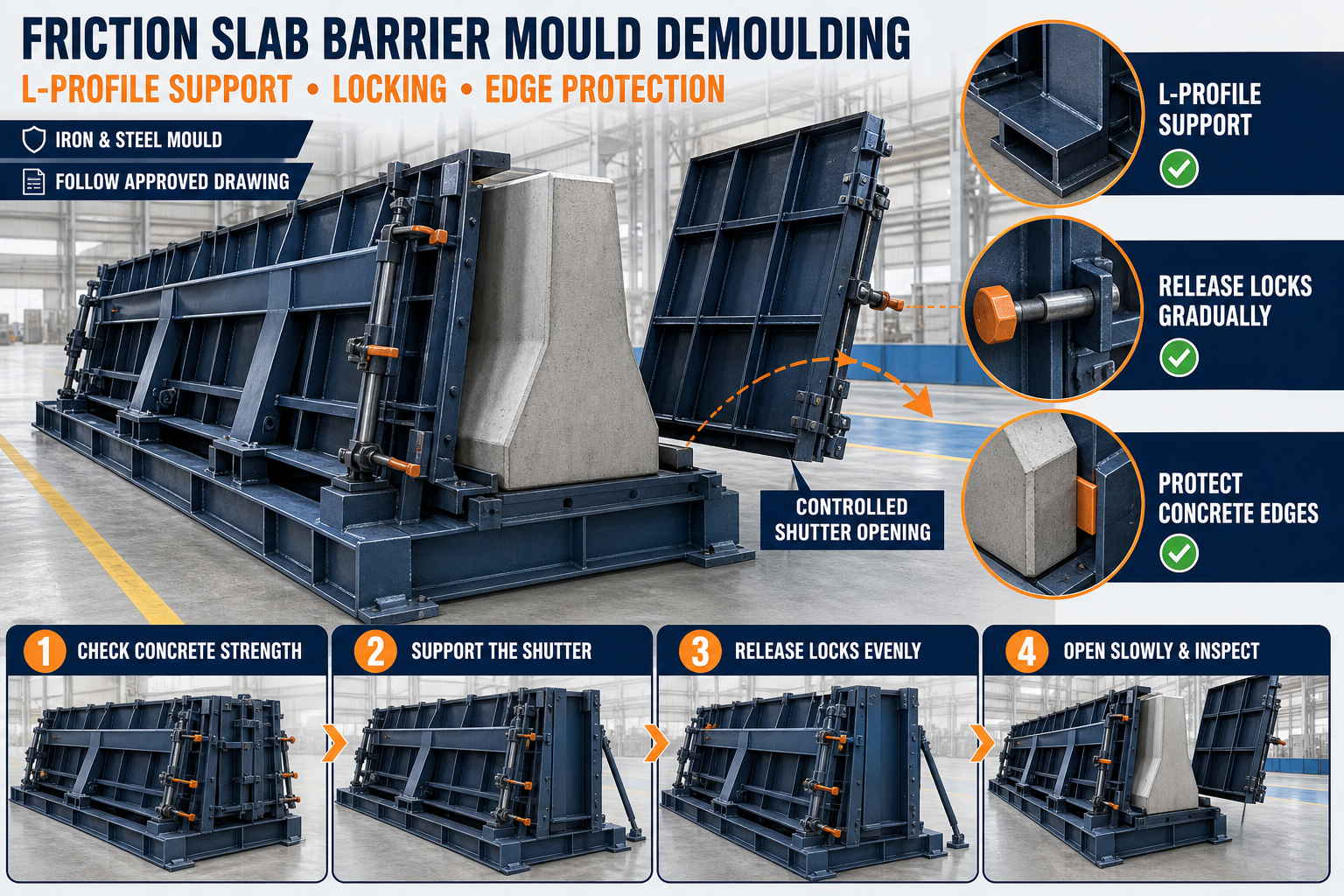
Safe Demoulding Sequence
Locks should be released only after the concrete achieves the required stripping strength.
A controlled sequence includes:
1. Support the shutter where required. 2. Remove hardened slurry around the locks. 3. Release wedges gradually. 4. Use a balanced release sequence. 5. Confirm that every lock is disengaged. 6. Open the shutter slowly. 7. Protect concrete edges. 8. Inspect locks and seals after opening.
Do not stand in the path of a released shutter.
Common Wedge Lock Problems
Wedge Will Not Enter the Guide
Check concrete buildup, guide alignment, shutter position, wedge bending and flange alignment.
Wedge Becomes Loose During Vibration
Inspect taper wear, guide clearance, retaining arrangement and bracket movement.
Lock Requires Excessive Force
Possible causes include a misaligned shutter, damaged guide, dirty flange, crushed seal or bent wedge.
Wedge Cannot Be Released
Check excessive engagement, slurry entry, deformed components and mould loading.
Repeated Slurry Leakage
Inspect the complete flange and seal rather than only tightening the nearest lock.
Lock Bracket Cracks
Possible causes include shutter misalignment, excessive force, structural vibration or poor previous repair.
Concrete Fin Appears Along the Joint
Check flange gaps, damaged gaskets, uneven lock pressure and concrete buildup.
Post-Casting Inspection
After every casting cycle, inspect:
• Wedge position • New wear marks • Loose retainers • Slurry buildup • Flange leakage • Seal condition • Bracket movement • Cracked welds • Shutter alignment • Concrete-fin locations
Clean locks before slurry hardens.
Preventive Maintenance Checklist
Daily Checks
• Clean all wedge locks • Inspect visible damage • Check retainers • Observe lock engagement • Inspect slurry-leakage areas • Check flange cleanliness
Scheduled Checks
• Inspect wedge taper • Measure pin and guide wear • Check locking brackets • Examine welded connections • Verify shutter alignment • Inspect seals • Lubricate approved points • Compare lock engagement • Check mechanical stops • Record replaced parts
When Should Production Be Stopped?
Stop using the highway barrier mould if you find:
• Cracked locking brackets • Broken or bent wedges • Missing retaining components • Locks that loosen during vibration • Severely distorted flanges • Major slurry leakage • Shutter movement during casting • Damaged hinges • Locks that cannot engage safely • Unstable mould supports
Production should resume only after repair, alignment verification and a controlled empty-mould test.
Conclusion
Highway barrier mould wedge lock maintenance requires more than driving the wedge farther into its guide. Correct operation depends on sound wedge geometry, aligned brackets, straight flanges, healthy seals and balanced lock engagement.
Insufficient clamping can cause slurry leakage and concrete fins, while excessive clamping can damage the heavy iron shutter and sealing system. All locks should therefore be inspected, cleaned and adjusted as one complete system.
Paras Steel Industries manufactures heavy-duty iron and structural-steel highway barrier moulds according to customer requirements and approved drawings. Regular wedge-lock maintenance helps support reliable joint closure, cleaner concrete barriers and consistent precast production.