
Precast Infrastructure Moulds
Highway Barrier Mould End-Shutter Setup: Barrier Length, Connection Details and Slurry Sealing
An end shutter closes the highway barrier mould and establishes the finished barrier length and end profile. Incorrect alignment, misplaced connection inserts or uneven locking can cause dimensional variation, concrete fins and slurry leakage. This guide explains end-shutter positioning, sealing and inspection for heavy-duty iron highway barrier moulds.
By Paras Steel Industries ·
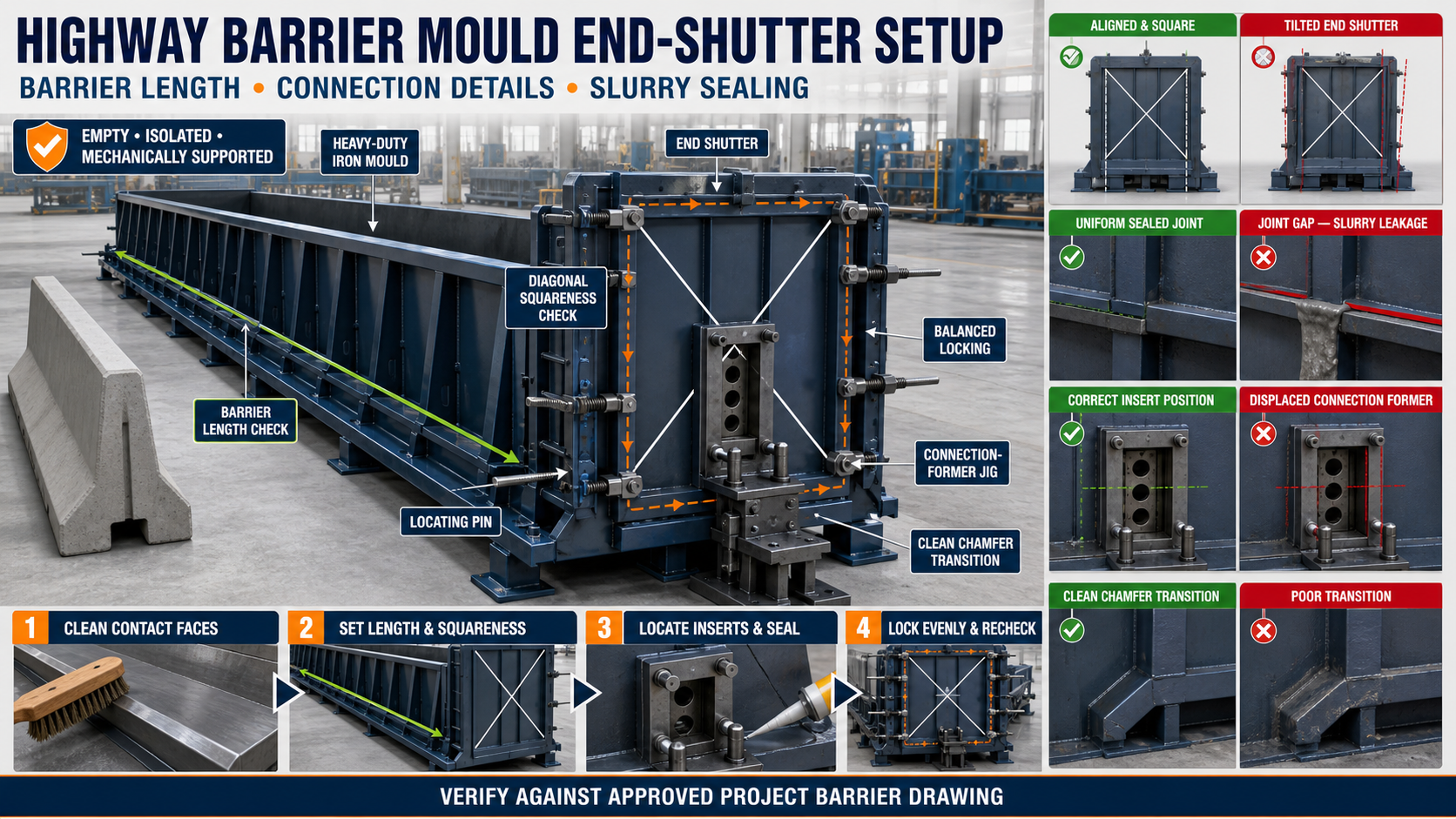
Highway Barrier Mould End-Shutter Setup: Barrier Length, Connection Details and Slurry Sealing
Highway Barrier Mould End-Shutter Setup: Barrier Length, Connection Details and Slurry Sealing
Precast highway barriers are used along road medians, bridge approaches, work zones and other infrastructure locations according to the project design.
A barrier mould must produce a consistent concrete profile, accurate overall length and correctly positioned end details. The end shutters play an important role in achieving these requirements.
Each end shutter closes the casting cavity, resists fresh concrete pressure and forms the corresponding barrier end. If the shutter is misaligned, damaged or incorrectly locked, the finished barrier may have dimensional errors, concrete fins, slurry leakage or connection problems.
What Is a Highway Barrier Mould End Shutter?
An end shutter is a removable or hinged iron component installed at either end of a highway barrier mould.
A typical end-shutter assembly may include:
• Heavy-duty steel face plate • Structural stiffeners • Locating pins • Guide blocks • Wedge locks • Screw clamps • Bolted connections • Sealing surfaces • Connection-detail inserts • Chamfer strips • Lifting or handling points • Mechanical stops
The exact design depends on the barrier profile and approved project drawing.
Role of the End Shutter
The end shutter helps:
• Establish the finished barrier length • Form a square or specified end face • Close the mould cavity • Prevent concrete leakage • Support connection inserts • Maintain profile continuity • Resist pressure during casting • Protect dimensional accuracy • Create specified chamfers or recesses • Support repeatable production
The shutter should remain stable during concrete placement and vibration.
Highway Barrier Profiles
Highway barrier moulds may manufacture different concrete profiles, including:
• New Jersey profile • F-shape profile • Project-specific road barrier • Median barrier • Bridge parapet or compatible barrier profile • Friction-slab barrier where separately designed
The end shutter must match the corresponding cross-section and connection arrangement. Formers from different barrier profiles should not be interchanged without approved design verification.
Why End-Shutter Accuracy Is Important
Incorrect setup can produce:
• Variable barrier length • Out-of-square end faces • Incorrect connection locations • Mismatched adjoining barriers • Concrete fins • Slurry leakage • Honeycombing near the end • Damaged corners • Difficult demoulding • Increased repair work • Installation delays
A small mould error can be repeated across an entire production batch.
Common Causes of End-Shutter Misalignment
End-shutter position can change because of:
• Hardened concrete on contact surfaces • Worn locating pins • Bent guide components • Loose or uneven locks • Distorted face plate • Cracked welds • Impact during handling • Damaged sealing strip • Incorrect lifting • Mould-bed movement • Side-shutter misalignment • Concrete buildup around hinges • Previous repair distortion • Excessive vibration
The complete assembly should be inspected instead of correcting only the visible gap.
Preparing the Mould for End-Shutter Setup
Before installing or adjusting the shutter:
• Empty and clean the mould • Remove hardened concrete and slurry • Isolate hydraulic or powered equipment • Release stored pressure safely • Mechanically support movable shutters • Inspect the mould foundation • Secure the side shutters • Identify the approved reference datum • Review the barrier drawing • Verify the correct end shutter and inserts
Never work between shutters that can move unexpectedly.
Identify the Correct End Shutter
The two ends of a barrier may contain different connection details or orientations.
Before installation, confirm:
• Inlet or outlet orientation where applicable • Left and right shutter identification • Casting direction • Required barrier profile • Connection-detail arrangement • Chamfer position • Recess or insert location • Project identification • Compatibility with the side shutters
Clearly marked components reduce setup errors when several mould sizes or barrier types are produced.
Establishing a Fixed Reference Datum
End-shutter alignment should be checked from a verified reference.
Possible datums include:
• Mould-bed centreline • Fixed side-shutter reference face • Machined stop • Base-frame datum • Approved alignment block • Verified opposite end shutter
Avoid measuring from concrete deposits, damaged plate edges or movable components that have not been checked.
How to Check Barrier Length
Barrier length should be checked at several points, not from only one edge.
A general check may include:
• Overall mould-cavity length • Upper end-to-end measurement • Lower end-to-end measurement • Measurements along both sides • Centreline measurement • Comparison with the approved drawing
Different upper and lower measurements may indicate a tilted end shutter.
No generic barrier length should be assumed. The required dimensions must follow the approved project drawing.
Checking End-Shutter Squareness
The shutter should remain square or at the specified orientation relative to the mould bed.
Squareness may be checked using:
• Approved engineer’s square • Diagonal measurements • Laser alignment • Verified template • Upper and lower length comparison • Fixed reference stops
A shutter can appear fully closed while still leaning forward or sideways.
Checking Profile Continuity
The end shutter should match the barrier’s side-shutter profile cleanly.
Inspect:
• Lower toe or base transition • Main barrier slope • Upper section • Corner chamfers • Side-shutter intersections • Profile inserts • End-face contact • Joint lines
A step at the intersection can produce a concrete fin or distorted end profile.
Connection Details in Highway Barriers
Some barrier designs include project-specific connection details for alignment, lifting, joining or installation.
These may involve:
• Connection recesses • Steel inserts • Bolt-pocket formers • Dowel openings • Sleeve locations • Alignment keys • End grooves • Approved lifting inserts • Project-specific embedded components
Their exact design, material and position must follow the approved engineering drawing.
Do not invent or relocate connection details based only on a previous project.
Setting Connection Inserts
A general insert-positioning procedure may include:
1. Identify the Correct Insert
Confirm its type and mould location.
2. Clean the Former or Fixture
Remove concrete and slurry from all contact areas.
3. Position Using a Fixed Jig
Use an approved fixture or locating system rather than visual judgement.
4. Check Orientation
Confirm the insert faces the required direction.
5. Verify Edge and Centre Position
Measure from approved mould datums.
6. Secure the Insert
Prevent movement during concrete placement and vibration.
7. Check Reinforcement Clearance
Ensure the reinforcement cage does not displace the insert.
8. Recheck Before Casting
Confirm every connection detail during the pre-pour inspection.
Connection fixtures should be maintained with the same care as the main mould.
Reinforcement and Insert Clearance
Reinforcement should not interfere with the end shutter or connection formers.
Check that:
• Reinforcement follows the approved drawing • Required concrete cover is maintained • Bars do not push against inserts • Tie wire is kept clear of joints • Cage supports are stable • Connection components are properly fixed • Shutter closure does not move the cage
Do not force the end shutter closed against incorrectly positioned reinforcement.
Understanding End-Shutter Joint Gaps
A joint gap is the clearance between the end shutter and the adjoining side or base shutter.
An uneven gap can cause:
• Cement-slurry leakage • Concrete fins • Honeycombing • Rough corner finish • Loss of profile accuracy • Difficult demoulding • Extra grinding and repair
The complete contact line should be checked before concrete casting.
Common Causes of Slurry Leakage
Leakage may result from:
• Dirty contact surfaces • Bent shutter plate • Worn seals • Unequal locking pressure • Loose locating pins • Damaged chamfer strips • Cracked welds • Side-shutter distortion • End-shutter misalignment • Excessive vibration • Concrete trapped in the joint
Repeated leakage at the same point indicates a mechanical problem requiring correction.
Cleaning Contact Surfaces
Before closing the end shutter:
• Remove hardened concrete • Scrape away slurry deposits carefully • Clean locating pins and holes • Inspect the sealing face • Remove rust flakes • Clean chamfer-strip transitions • Check connection-former contact points • Ensure no tools remain in the cavity
Even a thin deposit can prevent complete shutter contact.
Sealing the End Shutter
Effective slurry sealing depends on accurate metal-to-metal alignment and approved sealing components.
A reliable sealing procedure may include:
• Cleaning all mating surfaces • Inspecting sealing strips • Replacing damaged approved seals • Checking the complete profile • Closing the shutter against fixed stops • Applying locks progressively • Inspecting corners and transitions • Performing an approved leakage check
Improvised packing should not replace proper shutter alignment.
End-Shutter Locking Systems
Highway barrier moulds may use:
• Wedge locks • Screw clamps • Toggle clamps • Pin-and-slot locks • Bolted flanges • Hydraulic locking • Combined locking systems
Locks should pull the shutter evenly against its contact surfaces without bending it.
Balanced Locking Sequence
The exact sequence depends on the mould design. A general process may include:
1. Engage Locating Pins
Confirm the shutter is seated against its guides.
2. Apply Central Locks Lightly
Hold the shutter in position.
3. Engage Remaining Locks
Start each lock without fully tightening it.
4. Tighten Progressively
Apply force in a balanced pattern.
5. Inspect Joint Gaps
Confirm the upper and lower joints remain consistent.
6. Verify Length and Squareness
Ensure the shutter has not moved.
7. Confirm All Locks
Perform a final visual and physical check before casting.
Avoid fully tightening one lock while the other side remains unsupported.
How to Identify Incorrect Locking
Warning signs include:
• One lock requires excessive force • Wedges seat at different depths • The shutter moves during tightening • Joint gaps change • The face plate bends • Locks loosen during vibration • Locating pins do not seat completely • Profile intersections remain open
Increasing locking force does not correct a bent or obstructed shutter.
Applying Mould Release Agent
Apply a suitable release agent to the clean end-shutter forming face.
The coating should be:
• Thin • Uniform • Compatible with the concrete finish • Applied around chamfers and recesses • Kept away from reinforcement where required • Free from excessive pooling
Too much release agent can affect surface appearance and collect contaminants.
Checks During Concrete Placement
Observe the mould from a safe position during casting.
Look for:
• Slurry appearing at joints • Lock movement • End-shutter vibration • Insert displacement • Local plate bulging • Reinforcement movement • Unusual metallic noise • Concrete escaping from corners
Stop the process safely if significant shutter movement or leakage occurs.
Effect of Vibration on End Shutters
Vibration compacts the concrete but can also loosen an inadequately secured shutter.
Before vibration:
• Check every lock • Confirm locating pins • Inspect supporting brackets • Verify insert security • Remove loose tools • Confirm the mould is properly anchored
Excessive or uncontrolled vibration can increase leakage and component wear.
Preparing for Demoulding
Before opening the mould:
• Confirm adequate concrete strength • Support the barrier unit • Isolate powered equipment • Release hydraulic pressure • Mechanically support shutters • Clean concrete around locks • Identify the approved opening sequence • Keep personnel away from pinch points • Prepare approved lifting equipment
The correct demoulding time depends on the concrete mix, curing method and product requirements.
Correct End-Shutter Demoulding Sequence
A general procedure may include:
1. Support the Concrete Barrier
Prevent unexpected movement.
2. Remove External Slurry
Clean hardened material around locks and joints.
3. Release Secondary Locks
Open locking points progressively.
4. Support the End Shutter
Prevent the heavy iron shutter from dropping.
5. Release Primary Locks
Open the remaining connections in the approved order.
6. Create Controlled Separation
Use the designed mechanism without striking the concrete.
7. Move the Shutter Along Its Approved Path
Avoid dragging it across connection details.
8. Protect Concrete Edges
Keep tools and shutter corners away from the barrier.
9. Inspect the End Face
Check dimensions, finish and connection details.
Never allow the shutter to hang from one hinge or remaining lock unless specifically designed for that condition.
Preventing Edge Damage
To protect barrier ends:
• Allow adequate concrete strength • Apply release agent correctly • Maintain chamfer strips • Remove concrete fins before forced movement • Release locks completely • Support the barrier • Open shutters evenly • Avoid sudden impact • Keep lifting equipment clear of edges • Inspect connection formers for undercut or damage
Repeated edge damage should be traced to its exact mould location.
Post-Demoulding Inspection
Inspect the finished barrier end for:
• Overall length • End-face squareness • Profile completeness • Connection-detail position • Chamfer continuity • Concrete fins • Chips and cracks • Honeycombing • Surface defects • Joint compatibility • Compliance with the approved drawing
Record defects by mould and shutter position.
Troubleshooting Common Problems
Problem: Barrier Length Varies
Possible causes:
• End shutter has shifted • Locating stop is worn • Upper and lower locks are uneven • Contact surfaces contain concrete • Opposite end shutter is misaligned
Problem: Slurry Leaks From the Bottom Corner
Possible causes:
• Local joint gap • Damaged seal • Bent shutter corner • Concrete buildup • Weak or loose lock • Misaligned base shutter
Problem: Connection Insert Is Displaced
Possible causes:
• Fixture is loose • Reinforcement pushed the insert • Vibration moved the former • Locating jig is worn • Orientation was incorrect
Problem: Concrete Fin Appears Around the End Face
Possible causes:
• Gap between shutters • Damaged sealing surface • Incorrect locking sequence • Distorted plate • Worn locating pins
Problem: End Shutter Is Difficult to Open
Possible causes:
• Concrete bonded to the forming face • Locks remain partially engaged • Concrete fin is trapping the joint • Hinge or guide is damaged • Connection former has created an undercut • Shutter is distorted
Problem: Locks Loosen During Vibration
Possible causes:
• Worn wedge surfaces • Incorrect adjustment • Damaged brackets • Shutter misalignment • Excessive vibration • Concrete buildup preventing full closure
End-Shutter Maintenance Checklist
After each casting cycle:
• Clean the forming face • Remove slurry from all joints • Clean locating pins • Inspect locks and wedges • Check hinges and guides • Inspect seals • Examine chamfer strips • Check connection fixtures • Inspect structural stiffeners • Look for cracked welds • Check the shutter for bending • Lubricate approved moving points • Apply corrosion protection during storage • Record recurring leakage areas
Routine cleaning prevents hardened material from changing the shutter position.
Common Setup Mistakes
Measuring From a Dirty Surface
Concrete deposits create false measurements and prevent complete closure.
Checking Length at Only One Point
A tilted shutter may still produce one apparently correct measurement.
Tightening One Side Fully
Uneven locking can pull the shutter out of square.
Positioning Inserts by Eye
Connection details should be located using approved jigs or datums.
Using Excessive Seal Material
Excess material may prevent the shutter from seating properly.
Ignoring Worn Locating Pins
A worn pin can allow repeated movement between casting cycles.
Forcing the Shutter Closed
This may distort the plate, reinforcement or connection former.
Pre-Pour End-Shutter Checklist
Before placing concrete, confirm:
• Correct shutter is installed • Barrier profile matches the production drawing • Casting direction is correct • Contact surfaces are clean • Locating pins are seated • Barrier length is verified • End-face squareness is checked • Connection details are correctly positioned • Reinforcement has adequate clearance • Chamfer strips are aligned • Sealing surfaces are closed • Locks are progressively tightened • Release agent is uniformly applied • No tools remain inside the mould
Benefits of Correct End-Shutter Setup
Accurate setup provides:
• Consistent barrier length • Square and clean end faces • Correct connection-detail positioning • Reduced slurry leakage • Fewer concrete fins • Lower edge-damage risk • Easier demoulding • Better compatibility between units • Reduced repair and rejection • More reliable infrastructure production
Conclusion
Highway barrier mould end shutters control the finished barrier length, end-face profile, connection-detail position and slurry sealing. Their alignment should be checked from verified mould datums rather than from unclean or movable surfaces.
Clean contact faces, correctly seated locating pins and balanced locking help prevent dimensional variation and leakage. Connection inserts should always follow the approved engineering drawing and be secured using suitable fixtures.
A properly aligned heavy-duty iron highway barrier mould helps manufacturers produce consistent precast barriers with clean ends, accurate project-specific details and reliable installation quality.