
Precast Pole Mould Guide
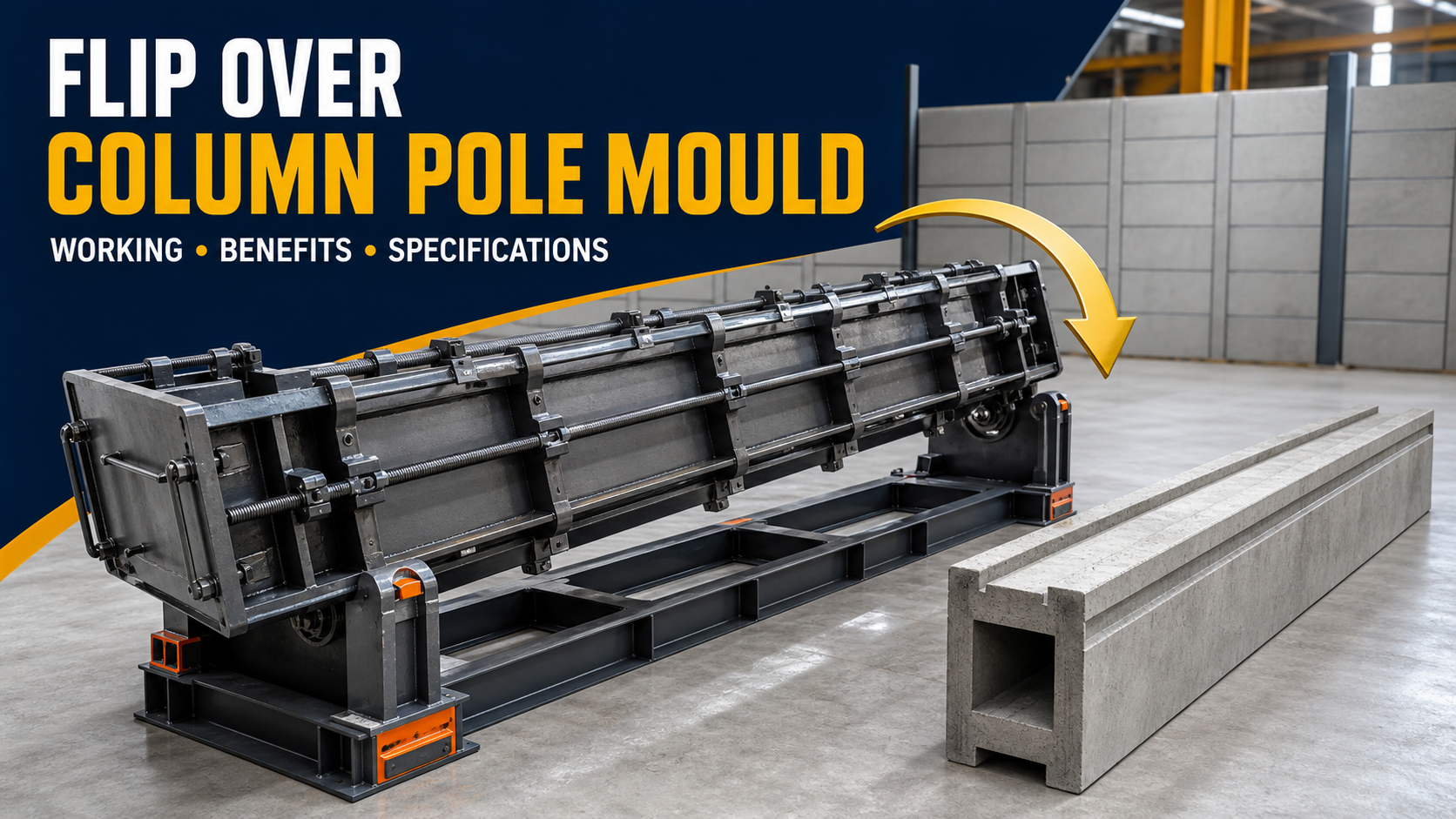
Flip Over Column Pole Mould: Working Process, Benefits and Specifications
A flip over column pole mould produces grooved precast H-posts for boundary wall panels. Explore its working process, sizes, benefits, specifications and selection factors.
By Paras Steel Industries ·
Flip Over Column Pole Mould: Working Process, Benefits and Specifications
Flip Over Column Pole Mould: Working Process, Benefits and Specifications
Precast boundary walls require accurately manufactured columns that can hold concrete panels firmly after installation. A flip over column pole mould helps manufacturers produce consistent H-profile concrete posts with grooves on both sides.
The grooves allow precast wall panels to slide between two columns, creating a fast and practical boundary wall system. The flip-over arrangement simplifies mould positioning, concrete casting and controlled demoulding when used with the correct production setup.
This guide explains the flip over column pole mould working process, standard sizes, heavy-duty iron construction, production benefits, applications, maintenance and important buying factors.
What Is a Flip Over Column Pole Mould?
A flip over column pole mould is a reusable precast mould designed to manufacture concrete columns or poles for boundary wall systems.
It commonly produces an H-shaped column with a groove on both opposite sides. During wall installation, precast concrete panels are inserted into these grooves.
The mould is manufactured using heavy-duty iron plates, channels, stiffeners, tie rods, locking bars and handles. Its rigid construction helps prevent expansion and dimensional changes during concrete pouring and vibration.
The term “flip over” refers to the mould’s operating or demoulding arrangement. Depending on its design, the mould can be repositioned or carefully turned as part of the production process to simplify removal of the finished concrete pole.
The exact flipping and demoulding procedure depends on mould size, product weight, factory equipment and the manufacturer’s operating instructions.
What Is an H-Profile Column Pole?
An H-profile column pole contains grooves on two opposite sides. When viewed in cross-section, its profile resembles the letter H.
The grooves perform an important function in a precast boundary wall system. Each panel end enters the groove of an adjoining column, creating a continuous wall.
The H-column system offers several advantages:
Fast panel installation
Controlled panel alignment
Reduced on-site masonry work
Replaceable individual panels
Standardised wall construction
Clean boundary-wall appearance
Suitability for long perimeter projects
The groove dimensions must match the thickness and edge design of the concrete wall panels.
Standard Flip Over Column Pole Mould Specifications
Common specifications for a flip over H-column mould may include:
Column cross-section: 150 mm × 150 mm
Equivalent size: Approximately 6 in × 6 in
Standard column lengths: 7 ft, 8 ft, 9 ft and 10 ft
Panel groove width: Approximately 50 mm to 65 mm
Groove depth: Approximately 25 mm to 35 mm on both sides
Iron plate thickness: Approximately 4 mm to 6 mm
Column profile: Dual-side groove H-post
Reinforcement compatibility: Four-bar TMT reinforcement cage or prestressed wire arrangement
Compaction compatibility: Table vibration or external shutter vibration
Production output: One concrete column per mould during each casting cycle
Custom lengths, cross-sections and groove dimensions can be manufactured according to the customer’s approved drawing.
The final column dimensions and reinforcement must be determined by the project engineer.
Main Parts of a Flip Over Column Pole Mould
Mould Body
The main mould body creates the external shape of the concrete column. It is manufactured using heavy-duty iron plates and reinforced supporting sections.
Central Groove Formers
The groove-forming sections create slots on both sides of the concrete column. Their width and depth must match the intended wall-panel dimensions.
Outer Stiffener Channels
External channels reinforce the mould body and help prevent plate expansion during concrete pouring and vibration.
Tie Rods
Tie rods hold the mould sections together and resist the outward pressure of fresh concrete.
Clamping Bars
Clamping bars distribute locking pressure across the mould. They help maintain a consistent column cross-section.
Nut-Bolt Locks
Heavy-duty nuts and bolts secure the mould before concrete filling and vibration.
End Plates
End plates control the final column length and prevent concrete leakage from the mould ends.
Handling Pipes or Handles
Welded iron pipe handles may be provided at both ends for controlled positioning. Manual handling should only be used when the mould weight remains within safe limits.
Alignment Points
Alignment arrangements help workers close the mould correctly after every production cycle.
How Does a Flip Over Column Pole Mould Work?
The complete working process includes mould preparation, reinforcement placement, concrete filling, compaction, curing, flipping or repositioning and demoulding.
Step 1: Clean the Mould
Remove concrete residue, cement slurry and dust from the internal mould surfaces. Groove-forming sections and flange joints require special attention.
Hardened concrete deposits can affect column dimensions and make demoulding difficult.
Step 2: Inspect the Mould
Check the iron plates, stiffener channels, tie rods, locking bars, nuts, bolts, handles and end plates.
Do not use the mould if structural components are loose, cracked or bent.
Step 3: Apply Release Oil
Apply a thin and uniform layer of suitable mould-release oil to the internal surfaces.
Too little oil can cause concrete to stick to the mould. Excessive oil may stain the finished column or create an inconsistent surface.
Step 4: Position the Reinforcement
Place the approved reinforcement cage or prestressed wire arrangement inside the mould.
A typical reinforcement arrangement may use four TMT bars with suitable stirrups. The actual bar diameter, stirrup spacing and concrete cover must follow the structural drawing.
Step 5: Close and Lock the Mould
Close the mould sections carefully and install the end plates. Tighten the clamping bars, tie rods and nut-bolt locks uniformly.
Uneven tightening can produce an incorrect column section or cause slurry leakage.
Step 6: Check Dimensions and Alignment
Verify the following before casting:
Overall mould length
Column cross-section
Groove width
Groove depth
Reinforcement position
Concrete cover
End-plate alignment
Insert position, if applicable
Step 7: Pour the Concrete
Fill the mould gradually using the specified concrete mix. Concrete should be distributed along the length instead of being discharged at only one point.
Controlled placement reduces reinforcement movement and concentrated pressure on the mould body.
Step 8: Compact the Concrete
Compact the concrete using a vibrating table or external shutter vibrators, depending on the production setup.
Vibration helps remove trapped air from the concrete, especially around the groove-forming sections and reinforcement cage.
Avoid excessive vibration because it can cause concrete segregation and slurry leakage.
Step 9: Finish the Open Surface
Level and finish the exposed concrete surface according to the required column profile.
Step 10: Allow the Concrete to Set
Keep the mould undisturbed until the concrete develops sufficient strength for safe handling and demoulding.
Demoulding time depends on:
Concrete grade
Mix design
Ambient temperature
Cement type
Curing method
Column dimensions
Production schedule
Step 11: Release the Locks
Loosen the tie rods, clamping bars, bolts and end plates systematically. Do not force the mould open while the concrete is still weak.
Step 12: Flip or Reposition the Mould
The mould may be carefully turned or repositioned according to its operating design. This provides access to the opening side and helps release the concrete column.
Large or heavy moulds should only be flipped using suitable mechanical equipment. Workers must not manually rotate a mould that exceeds safe handling limits.
Step 13: Remove the Concrete Column
Separate the mould sections carefully and lift or roll out the finished pole using the approved method.
Avoid striking the concrete corners and grooves with heavy tools.
Step 14: Continue Curing
Transfer the column to the curing area and continue curing according to the concrete specification.
Step 15: Inspect the Finished Product
Check the column length, cross-section, groove dimensions, straightness and concrete surface before storage or dispatch.
Benefits of a Flip Over Column Pole Mould
Easy Demoulding
The flip-over arrangement can provide better access during demoulding and reduce uncontrolled pulling of the concrete product.
Accurate H-Profile Production
Precision groove formers help produce consistent slots on both sides of the column.
Reduced Mould Expansion
Tie rods, stiffener channels and clamping bars help prevent the mould from opening or bulging under concrete pressure.
Repeatable Dimensions
A rigid iron body supports consistent column length, cross-section and groove dimensions during repeated production.
Efficient Boundary Wall Installation
Properly manufactured grooves allow wall panels to slide into position at the construction site.
Vibration Compatibility
The mould can be configured for use with table vibrators or external shutter vibrators.
Multiple Length Options
Moulds can be manufactured for common 7 ft, 8 ft, 9 ft and 10 ft column lengths.
Long Production Life
Heavy-duty iron construction and correct maintenance allow the mould to support repeated casting cycles.
Reduced Finishing Work
A smooth and well-maintained internal surface produces cleaner concrete faces and grooves.
Custom Manufacturing
Column size, length, groove dimensions, plate thickness and locking arrangements can be customised according to the product drawing.
Importance of Heavy-Duty Iron Construction
Fresh concrete produces outward pressure on the mould. Mechanical vibration further increases the load on plates, joints and locking components.
A weak mould may expand or twist during production. This can cause:
Incorrect column cross-section
Uneven groove dimensions
Bent concrete columns
Slurry leakage
Rough surfaces
Difficulty during panel installation
Higher rejection rates
Heavy-duty iron plates and external channels help maintain mould rigidity.
Common plate thicknesses may range from approximately 4 mm to 6 mm. However, plate thickness should not be evaluated alone.
The complete strength of the mould depends on:
Iron plate thickness
Stiffener channel size
Spacing between stiffeners
Tie-rod diameter and quantity
Clamping arrangement
Column length
Concrete volume
Vibration intensity
Frequency of production
A longer mould may require additional stiffening even if the column cross-section remains unchanged.
Applications of Flip Over Column Poles
Industrial Boundary Walls
H-profile columns support precast panels around factories, manufacturing units and industrial estates.
Warehouses and Logistics Parks
The system can create secure perimeter walls around warehouses, transport yards and distribution centres.
Residential Societies
Precast columns and panels are suitable for gated communities, housing projects and private estates.
Farmhouses and Agricultural Properties
The columns can be used for affordable and fast perimeter-wall installation around farms and rural properties.
Solar Power Plants
Precast boundary walls protect solar parks, control rooms and related infrastructure.
Electrical Substations
H-columns can support perimeter wall panels around electrical and utility facilities.
Commercial Properties
Precast wall systems are suitable for offices, commercial parks, institutions and educational campuses.
Construction Sites
Temporary or permanent precast wall systems can provide site separation and security.
Production Capacity
One mould normally produces one concrete pole during each casting cycle. Actual daily production depends on the complete factory workflow.
Important production factors include:
Number of moulds
Concrete setting time
Curing system
Reinforcement preparation
Mould cleaning time
Worker availability
Concrete batching capacity
Vibration equipment
Material-handling arrangement
Number of factory shifts
For example, if one casting cycle requires a full day, ten moulds may produce approximately ten poles per working cycle. Actual output can vary according to concrete strength development and factory conditions.
Manufacturers should calculate the required number of moulds using the project quantity and delivery schedule.
Reinforcement Options
The mould may accommodate different reinforcement arrangements depending on the column design.
TMT Reinforcement Cage
A conventional cage may contain four longitudinal TMT bars connected with stirrups.
Prestressed Wire Arrangement
Selected pole designs may use prestressed high-tensile wires. Prestressed production requires specialised beds, anchoring equipment and controlled tensioning.
The mould manufacturer supplies the mould according to the required production configuration. The structural engineer remains responsible for approving reinforcement and prestressing details.
Importance of Groove Dimensions
The grooves must be compatible with the concrete wall panels.
If the groove is too narrow, panels may not enter easily. If it is too wide, the panels may move after installation.
Important matching dimensions include:
Wall-panel thickness
Panel-end thickness
Groove width
Groove depth
Installation clearance
Grouting allowance
Common groove widths may range from approximately 50 mm to 65 mm, while groove depths may range from approximately 25 mm to 35 mm.
The customer should share both the column and wall-panel drawings before ordering the mould.
Quality Checks for Finished Columns
Each concrete column should be checked before dispatch.
Overall Length
Verify that the finished pole matches the required installation height and foundation depth.
Cross-Section
Measure the width and thickness at multiple points along the column.
Groove Width and Depth
Check both grooves using suitable measuring tools or a panel sample.
Straightness
Place the column on a suitable inspection surface and check for bending or twisting.
Concrete Surface
Inspect for cracks, honeycombing, exposed reinforcement and chipped groove edges.
Concrete Strength
Confirm that the concrete has achieved the specified strength before transportation or installation.
Reinforcement Cover
Ensure that the reinforcement is adequately covered according to the approved drawing.
How to Prevent Slurry Leakage
Cement slurry can leak from loose joints during vibration.
To minimise leakage:
Clean all flange joints before assembly.
Inspect mould edges for bending.
Tighten nuts and bolts uniformly.
Check end-plate alignment.
Repair damaged groove formers.
Use suitable sealing arrangements where required.
Avoid uncontrolled concrete discharge.
Do not apply excessive vibration.
Persistent leakage normally indicates a panel-alignment or joint-maintenance problem.
Flip Over Column Pole Mould Price Factors
Column Length
Longer 9 ft and 10 ft moulds require more iron and supporting reinforcement than shorter moulds.
Column Cross-Section
Larger columns require wider plates and stronger supporting structures.
Iron Plate Thickness
A heavy-duty plate configuration generally costs more but provides better resistance to concrete pressure.
Number of Stiffeners
Long moulds may require additional channels and support ribs.
Groove Design
Custom groove widths, depths and profiles can affect fabrication complexity.
Locking System
The quantity and quality of tie rods, clamps, nuts and bolts influence the final price.
Flip-Over Arrangement
Handles, pivots, supports or other operating arrangements affect manufacturing cost.
Customisation
Special lengths, reinforcement provisions and insert locations may require custom engineering.
Order Quantity
Ordering several identical moulds may improve manufacturing and cost efficiency.
Transportation
Long column moulds require suitable loading space and transportation planning.
How to Select the Right Mould
Before ordering, share complete production information with the manufacturer.
Required details include:
Column drawing
Column cross-section
Total column length
Required groove width
Required groove depth
Wall-panel thickness
Reinforcement design
Daily production target
Concrete compaction method
Factory handling system
Number of moulds required
Project quantity
Delivery location
Do not purchase a mould based only on its outside appearance. Groove accuracy, structural rigidity and locking strength directly affect the finished column.
Questions to Ask the Manufacturer
Which iron plate thickness will be used?
How many stiffener channels are provided?
Which column lengths are available?
Can groove width and depth be customised?
Which clamping system is included?
Can the mould operate on a vibrating table?
Is manual flipping safe for this mould size?
Can lifting or mechanical handling points be provided?
Can the mould accommodate my reinforcement cage?
How will slurry leakage be controlled?
Is anti-rust primer and industrial paint applied?
Can the mould be manufactured from my technical drawing?
Mould Maintenance Tips
Clean the mould after every casting cycle.
Remove concrete deposits from the groove formers.
Apply release oil evenly.
Inspect all tie rods and clamps.
Replace damaged nuts and bolts.
Check the straightness of the mould body.
Repair bent side plates immediately.
Keep handles and lifting points in good condition.
Touch up damaged anti-rust paint.
Store the mould on a level surface.
Avoid hitting the mould with heavy hammers.
Check groove dimensions periodically.
Common Production Mistakes
Incorrect Groove Size
A column may be unusable if its grooves do not match the wall-panel thickness.
Weak Mould Locking
Loose tie rods can allow the mould to expand during vibration.
Uneven Reinforcement Cover
An incorrectly positioned reinforcement cage can reduce durability and product quality.
Excessive Vibration
Over-vibration may cause concrete segregation and slurry leakage.
Early Demoulding
Flipping or opening the mould before sufficient concrete strength develops may damage the pole and groove edges.
Unsafe Manual Handling
Long moulds and finished columns can be heavy. Mechanical assistance should be used whenever manual handling is unsafe.
Uneven Mould Support
A mould placed on an uneven surface can produce bent or twisted columns.
Ignoring Wall-Panel Drawings
The column and panel must function as one system. Their drawings should be reviewed together.
Safety During Flipping and Demoulding
The flip-over process must be planned carefully because the mould and concrete column can be heavy.
Important safety practices include:
Determine the total mould and product weight.
Use rated lifting equipment where required.
Inspect handles and lifting points.
Keep workers away from the turning path.
Use a stable and level work area.
Release clamps only in the correct sequence.
Never stand beneath a suspended mould.
Do not attempt uncontrolled manual rotation.
Use personal protective equipment.
Train workers in the approved operating method.
The mould manufacturer’s handling instructions and factory safety procedures should always be followed.
Conclusion
A flip over column pole mould is an efficient solution for manufacturing precast H-profile columns used in boundary wall systems. It produces consistent dual-side grooves that allow concrete wall panels to slide into position during installation.
For dependable production, the mould requires heavy-duty iron plates, external stiffener channels, reliable tie rods and accurate groove-forming sections. Column length, groove dimensions, reinforcement, vibration method and handling arrangements must be finalised before manufacturing the mould.
Paras Steel Industries manufactures heavy-duty iron flip over column pole moulds according to customer dimensions and production requirements. Customers can share their column drawing, wall-panel thickness, required pole length and daily production target to discuss a suitable configuration.
Frequently Asked Questions
What is a flip over column pole mould?
It is a reusable precast mould designed to manufacture grooved concrete H-posts for boundary wall panel installation.
What is the standard column size?
A common H-column cross-section is approximately 150 mm × 150 mm or 6 in × 6 in.
Which lengths are available?
Common lengths include 7 ft, 8 ft, 9 ft and 10 ft. Custom lengths can also be manufactured.
Which material is used for the mould?
Paras Steel Industries manufactures its moulds using heavy-duty iron plates, channels, stiffeners, tie rods and locking bars.
What is the standard plate thickness?
Depending on the design, the mould may use approximately 4 mm to 6 mm heavy-duty iron plates.
What is the purpose of the grooves?
The grooves hold the ends of precast concrete wall panels during boundary wall installation.
Can groove dimensions be customised?
Yes. Groove width and depth can be customised according to the wall-panel drawing.
Can the mould be used with a vibrating table?
Yes. The mould can be configured for table vibration or external shutter vibration.
How many columns can one mould produce?
One mould normally produces one column during each casting cycle.
Can I provide my own technical drawing?
Yes. Paras Steel Industries can review the required column dimensions, groove profile and production requirements for custom mould manufacturing.