
Precast Mould Guide
Flip-Over Column Pole Mould Pivot Maintenance: Rotation Balance, Stopper Position and Latch Inspection
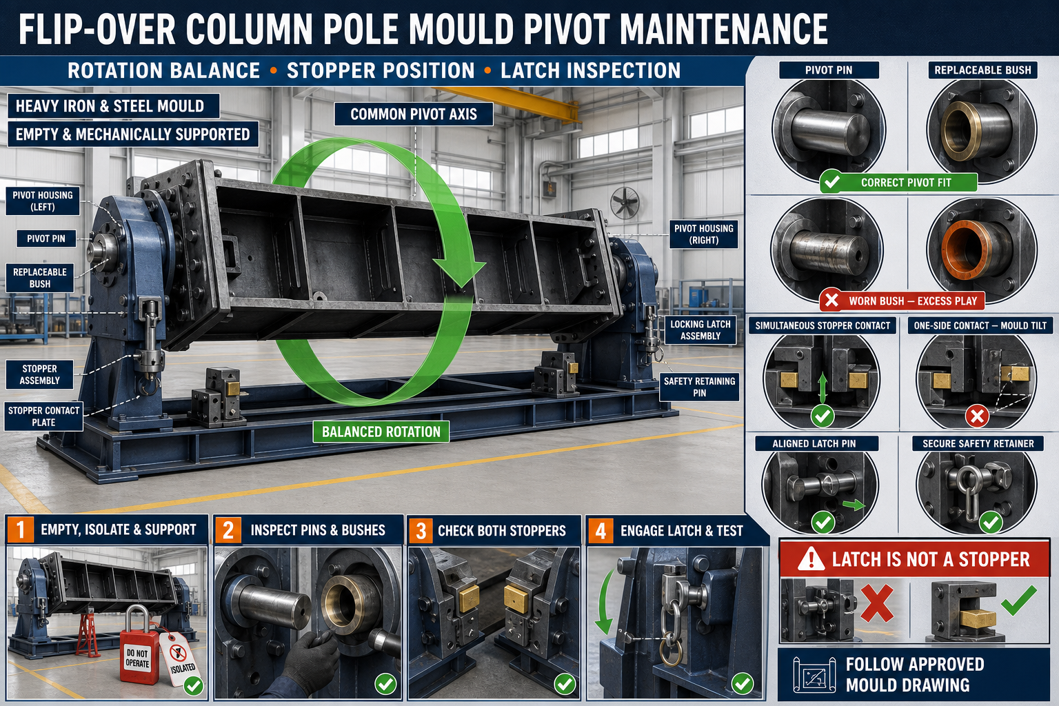
A worn pivot, incorrect stopper position or loose latch can make a flip-over column pole mould rotate unevenly or fail to lock securely. This guide explains safe support, pivot wear checks, balanced rotation and latch inspection.
By Paras Steel Industries ·
Flip-Over Column Pole Mould Pivot Maintenance: Rotation Balance, Stopper Position and Latch Inspection
Flip-Over Column Pole Mould Pivot Maintenance Guide
A flip-over column pole mould is designed to rotate between casting, finishing or demoulding positions. This movement can improve access to the precast pole and help operators complete production tasks in a controlled manner.
The complete rotating assembly is heavy. Its pivot pins, bushes, support brackets, mechanical stoppers and latches must therefore remain properly aligned and maintained.
A worn pivot can create sideways movement, while an incorrectly positioned stopper may allow the mould to rotate beyond its intended position. A damaged latch can fail to secure the mould after rotation.
This guide explains flip-over column mould pivot maintenance, including safe support, rotation-balance checks, stopper positioning and latch inspection.
What Is a Flip-Over Column Pole Mould?
A flip-over column pole mould is a heavy-duty iron or structural-steel mould mounted on a rotating support frame.
A typical system may include:
• Heavy iron mould body • Structural-steel base frame • Left and right pivot pins • Replaceable pivot bushes • Bearing housings • Pivot-support brackets • Rotation handles or approved drive mechanism • Mechanical stoppers • Stopper contact plates • Locking latches • Retaining pins • Counterbalance components where designed • Mould shutters and clamps • Lifting points
The exact arrangement should follow the approved mould drawing.
Purpose of the Flip-Over Mechanism
The rotation system may help with:
• Mould preparation • Reinforcement placement • Concrete finishing • Controlled demoulding • Access to shutters and locks • Inspection and cleaning • Handling of specific pole profiles • Reducing uncontrolled manual lifting
The mould should only rotate through its approved movement range.
Why Pivot Maintenance Is Important
The pivot supports and guides the complete rotating mould body.
Regular maintenance helps:
• Maintain smooth rotation • Reduce mould tilting • Prevent sideways movement • Protect support brackets • Maintain stopper alignment • Improve latch engagement • Reduce abnormal noise • Protect mould geometry • Support controlled operation • Reduce unexpected stoppages
Pivot problems should be corrected before the mould is loaded with concrete.
Common Warning Signs
Possible signs of pivot or rotation-system wear include:
• Mould drops suddenly during rotation • One side moves before the other • Rotation requires excessive force • Pivot produces knocking or grinding sounds • Mould shifts sideways • Pivot pin rotates inside the wrong component • Stopper contact becomes uneven • Latch holes do not align • Retaining pins become difficult to install • Grease contains metal particles • Pivot brackets show cracks • Mould does not remain level
Stop operation if rotation becomes unpredictable.
Safety Before Pivot Maintenance
The rotating mould contains substantial stored mechanical energy.
Before maintenance:
1. Empty the mould completely. 2. Remove concrete and loose components. 3. Park the assembly on firm, level ground. 4. Isolate hydraulic, electrical or powered rotation systems. 5. Apply the plant’s lockout and tagout procedure. 6. Rotate the mould to the approved maintenance position. 7. Support the rotating body mechanically at designated points. 8. Install retaining pins or maintenance locks. 9. Keep personnel away from the rotation path. 10. Wear suitable personal protective equipment.
Never rely only on a hydraulic cylinder, chain, latch or pivot pin to support the rotating mould during maintenance.
Mechanically Support the Mould
Approved support stands or maintenance blocks should carry the rotating mould body before pivot components are removed.
The support system should:
• Match the actual mould load • Stand on a firm surface • Contact reinforced structural areas • Prevent rolling or sliding • Remain outside pinch zones • Provide stable support at both ends • Allow safe component access
Do not use random scrap steel, wood or loose bricks as maintenance supports.
Clean the Pivot Area
Concrete slurry and hardened grease can hide component wear.
Clean:
• Pivot-pin ends • Bush faces • Bearing housings • Grease points • Retaining plates • Mounting bolts • Support brackets • Mechanical stoppers • Latches • Welded joints
Use non-damaging tools and collect contaminated grease correctly.
Initial Visual Inspection
Before dismantling the pivot system, inspect:
• Left and right pivot positions • Pin retainers • Bracket alignment • Bush seating • Grease leakage • Cracked welds • Bent plates • Loose bolts • Corrosion • Concrete buildup • Stopper contact • Latch engagement • Previous repairs
Record defects at each mould side separately.
Inspect the Pivot Pins
After mechanically supporting the mould, remove each pivot pin according to the approved procedure.
Check for:
• Diameter wear • Flat spots • Grooves • Scoring • Bending • Cracks • Corrosion • Damaged retaining grooves • Hammer damage • Uneven polishing • Blocked grease passages
A significantly worn or damaged pin should not be returned to service without approval.
Check Pivot-Pin Straightness
A bent pivot pin may:
• Bind during rotation • Wear the bush unevenly • Move the mould out of level • Damage its support bracket • Prevent latch alignment • Increase operating force
Use an approved inspection setup. Do not straighten a critical pivot pin using uncontrolled heating or hammering.
Inspect Pivot Bushes
Pivot bushes provide replaceable wear surfaces between pins and housings.
Check for:
• Oval internal wear • Cracks • Loose fit • Rotation inside the housing • Scoring • Damaged edges • Corrosion • Uneven wear • Blocked lubrication grooves • Metal particles
Replacing only the pin may not correct unwanted movement if the bush is also worn.
Check Pivot Clearance
Unwanted clearance may allow the mould to move vertically, sideways or along its pivot axis.
Inspect movement:
• With the mould empty • At both pivot ends • During controlled direction changes • At the pin retainers • Between the bush and housing • Along the mould centreline
Use a suitable measuring method and compare the result with the approved maintenance limit.
Inspect Pivot Housings and Brackets
The pivot brackets transfer the rotating mould load into the fixed base frame.
Check:
• Bracket straightness • Welded connections • Cracks • Bent plates • Elongated holes • Mounting-bolt condition • Corrosion • Base-frame connection • Previous repair quality • Unequal left and right positions
A cracked bracket requires qualified assessment and repair.
Check Pivot-Axis Alignment
Both pivot centres should lie on the intended common axis.
Misalignment can cause:
• Binding • Unequal bush wear • Heavy rotation • Side loading • Bracket cracking • Mould twisting • Stopper misalignment • Difficult latch engagement
Use an alignment bar, laser or approved fixture to verify the pivot axis.
Do not force a pivot pin through misaligned brackets.
Lubricating Pivots and Bushes
Correct lubrication reduces friction and wear.
Good practices include:
• Clean grease points first • Use the specified lubricant • Confirm lubrication passages are open • Apply a controlled quantity • Rotate the empty mould slowly where approved • Check lubricant distribution • Wipe away excess grease • Keep cement dust away • Record maintenance activity
Do not mix incompatible lubricants.
Insufficient Lubrication
Insufficient lubrication may cause:
• Grinding or squeaking • Jerky rotation • Pin scoring • Bush overheating • Corrosion • Rapid wear • Pivot seizure • Increased operating force
Excessive Lubrication
Too much grease can:
• Attract cement dust • Form an abrasive paste • Hide cracks • Spread onto floors • Contaminate casting areas • Make inspection difficult
Apply lubricant according to the approved maintenance procedure.
What Is Rotation Balance?
Rotation balance describes how smoothly and predictably the mould moves through its approved arc.
A balanced mould should:
• Begin moving in a controlled manner • Rotate without sudden acceleration • Keep both pivot sides coordinated • Avoid excessive sideways movement • Approach the stopper gradually • Remain stable at the locked position
Balance depends on the mould design, load position, pivot condition and rotation mechanism.
Always Test Rotation With an Empty Mould First
Before returning the mould to production, perform an empty controlled test.
Do not begin testing with:
• Fresh concrete • A precast pole • Loose reinforcement • Unsecured shutters • Tools resting on the mould • Workers inside the rotation zone
An unloaded test makes abnormal movement easier to identify.
Signs of Poor Rotation Balance
Possible signs include:
• Mould accelerates suddenly • One side appears to lead • Rotation stops and starts • Excessive force is required • Assembly swings near the stopper • Base frame lifts or shifts • Pivot noise changes through the rotation • Latches fail to align after movement
Identify the cause before further operation.
Possible Causes of Uneven Rotation
Uneven movement can result from:
• Worn pivot pins • Worn bushes • Misaligned pivot axis • Unequal lubrication • Bent mould frame • Loose support brackets • Off-centre attachments • Concrete buildup • Damaged rotation mechanism • Uneven foundation • Incorrect counterbalance • Obstruction near one side
Do not correct poor balance only by applying more operating force.
Inspect the Base Frame
The fixed structural-steel frame must remain level and stable.
Check:
• Foundation contact • Anchor points • Cross members • Longitudinal members • Pivot-support connections • Welded joints • Frame squareness • Corrosion • Impact damage • Previous repairs
A twisted frame can misalign both pivots.
Inspect the Rotation Mechanism
Depending on the design, rotation may be controlled by:
• Manual handle • Geared mechanism • Chain drive • Hydraulic cylinder • Mechanical jack • Approved lifting system
Inspect the specific mechanism for:
• Mounting security • Pins and bushes • Chains or gears • Hydraulic leaks • Handles • Retainers • Mechanical stops • Unwanted play • Structural damage
Follow the component manufacturer’s maintenance requirements.
Mechanical Stopper Function
A stopper limits rotation and establishes the mould’s final position.
A typical stopper may include:
• Welded stop block • Adjustable stop bolt • Contact pad • Reinforced bracket • Retaining nut • Replaceable wear plate
The stopper must contact a reinforced part of the rotating frame.
Inspect Stopper Position
Check:
• Left and right stopper locations • Contact at the approved mould position • Full contact across the stop face • Bolt and locknut condition • Welded bracket condition • Stopper wear • Bent contact plates • Concrete buildup • Interference with other components
Both sides should contact according to the mould design.
Signs of Incorrect Stopper Position
Incorrect positioning may cause:
• Mould stops before reaching level • Mould rotates too far • Latch holes do not align • One stopper contacts before the other • Pivot load becomes uneven • Shutter position changes • Mould frame twists • Rotation mechanism remains loaded
Correct the stopper before adjusting the latch.
Do Not Use the Latch as a Stopper
A latch is intended to secure the mould after it reaches its designed position. It should not absorb the impact of uncontrolled rotation.
Using the latch as a stopper can:
• Bend the latch pin • Crack the bracket • Enlarge pin holes • Damage welds • Create unsafe engagement • Misalign the mould
The rotating body should reach its mechanical stop before the latch is engaged.
Inspect Stopper Contact Plates
Contact plates may wear or deform after repeated use.
Check for:
• Uneven polishing • Cracks • Dents • Bending • Loose mounting • Weld damage • Metal burrs • Reduced contact area
Replace or repair damaged wear plates through the approved procedure.
Latch System Function
The latch secures the mould at the required operating position.
A latch assembly may include:
• Latch body • Locking pin • Guide bracket • Handle • Bush • Retaining clip • Lock plate • Safety pin • Welded support
The exact system should follow the approved mould design.
Latch Inspection
Check:
• Pin straightness • Pin wear • Hole elongation • Bracket cracks • Retaining components • Handle condition • Full engagement • Sideways movement • Corrosion • Concrete contamination • Previous repair welds • Safety-lock operation
A latch that cannot fully engage should not be used.
Latch Alignment
After the mould contacts its stopper, the latch pin should align without heavy force.
If it does not align, inspect:
• Stopper position • Pivot wear • Base-frame level • Mould distortion • Latch-bracket movement • Concrete buildup • Incorrect previous adjustment • Unequal pivot clearance
Do not force a misaligned latch pin with heavy hammering.
Full Latch Engagement
Confirm:
• Pin passes through all designed members • Retainer is installed • Safety clip is secure • Latch handle is in the approved position • No excessive gap remains • Pin is not carrying unintended stopper load • Engagement is repeatable
Use a visible inspection mark where approved.
Inspect Latch Pin and Bush
Check for:
• Grooves • Bending • Scoring • Rust • Cracks • Oval bush wear • Damaged retaining holes • Excessive clearance • Blocked lubrication points
Replace worn components with approved matching parts.
Balanced Latch Adjustment
Where adjustable latch brackets are provided:
1. Place the empty mould against the mechanical stopper. 2. Confirm both pivot positions. 3. Check that the mould is level. 4. Install the latch pin loosely. 5. Adjust the bracket gradually. 6. Confirm free pin movement. 7. Tighten mounting fasteners. 8. Recheck stopper contact. 9. Install retaining components. 10. Repeat the rotation and locking test.
Do not adjust the latch while the mould remains unsupported.
Inspect Mould Shutters and Locks
Loose shutters can change the rotating assembly’s balance.
Before rotation, check:
• All shutters are closed or secured as required • Mechanical locks are engaged • Removable parts are retained • Hydraulic hoses are protected • Reinforcement is not loose • Tools have been removed • Mould liners are secure
Nothing should fall during rotation.
Controlled Rotation Test
After completing maintenance:
1. Confirm the mould is empty. 2. Remove tools and loose parts. 3. Install all guards. 4. Clear the rotation zone. 5. Remove maintenance supports through the approved sequence. 6. Release the latch. 7. Rotate the mould slowly. 8. Observe both pivots. 9. Approach the stopper gradually. 10. Confirm balanced stopper contact. 11. Engage the latch. 12. Install the safety retainer. 13. Repeat the movement where required. 14. Record the result.
Stop immediately if the base frame moves or the mould accelerates unexpectedly.
Keep Personnel Outside the Rotation Arc
During testing and operation:
• Mark the movement zone • Use barriers where required • Keep the operator at the approved control point • Maintain access to the emergency stop • Do not touch moving components • Do not stand near stopper contact areas • Stop and isolate before making adjustments
Never attempt to slow a moving mould by hand.
Common Pivot and Latch Problems
Mould Rotates Heavily
Check lubrication, bush wear, pivot alignment, concrete buildup and rotation-mechanism condition.
Mould Drops Suddenly
Stop operation and inspect balance, pivot condition, drive mechanism, stoppers and any counterbalance arrangement.
One Pivot Wears Faster
Possible causes include axis misalignment, frame twist, unequal loading or lubrication failure.
Stopper Contacts on One Side Only
Inspect base level, pivot clearance, stopper adjustment and rotating-frame twist.
Latch Pin Does Not Enter
Check stopper position, pivot wear, mould level and latch-bracket alignment.
Latch Becomes Loose During Operation
Inspect pin clearance, retainer, bracket wear, vibration and full engagement.
Pivot Produces Knocking Noise
Check pin-and-bush clearance, retaining components and bracket movement.
Pivot Pin Is Difficult to Remove
Possible causes include remaining mould load, corrosion, bending, slurry buildup or bracket misalignment.
Repeated Bracket Cracks
Investigate pivot alignment, excessive clearance, stopper impact and structural load before completing another repair.
Preventive Maintenance Checklist
Before Every Use
• Inspect pivot retainers • Check stopper condition • Confirm latch engagement • Remove loose concrete • Inspect visible welds • Check that the rotation zone is clear • Confirm shutters and parts are secure
Scheduled Maintenance
• Inspect pivot pins • Check bush wear • Verify pivot-axis alignment • Lubricate approved points • Inspect pivot brackets • Check stopper positions • Examine contact plates • Inspect latch pins and bushes • Check the base frame • Conduct an empty rotation test • Record replaced parts and adjustments
When Should Production Be Stopped?
Stop using the flip-over mould if you find:
• Cracked pivot pins • Severely worn bushes • Broken pivot brackets • Missing retainers • Uncontrolled rotation • Failed mechanical stoppers • Latches that cannot fully engage • Cracked latch brackets • Moving base frame • Distorted rotating structure • Unsafe rotation mechanism • Mould that cannot remain securely locked
Production should resume only after repair and a successful empty-mould rotation test.
Conclusion
Flip-over column mould pivot maintenance is essential for controlled rotation and secure positioning. Pivot pins, bushes and support brackets must remain aligned and properly lubricated.
Mechanical stoppers should establish the final mould position before the latch is engaged. The latch must secure the mould without being used to absorb rotation impact or compensate for pivot misalignment.
Paras Steel Industries manufactures heavy-duty iron and structural-steel column pole moulds according to customer requirements and approved drawings. Planned pivot inspection, balanced rotation checks and reliable stopper-and-latch maintenance help support safer and more consistent precast production.