
Precast Infrastructure Moulds
Bridge Girder Mould Modular Extensions: Flange Joint, Slurry Seal and Length Changeover Guide
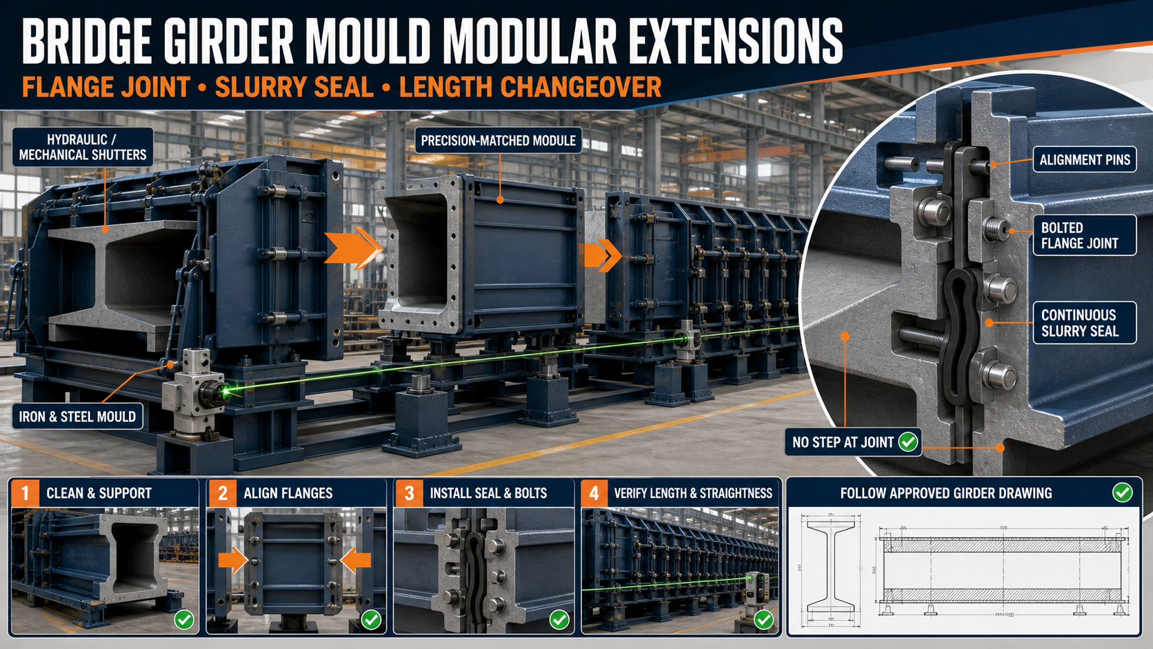
Modular bridge girder mould extensions allow compatible girder lengths to be produced using accurately matched steel sections. This guide explains flange-joint alignment, slurry sealing, length changeover and dimensional inspection.
By Paras Steel Industries ·
Bridge Girder Mould Modular Extensions: Flange Joint, Slurry Seal and Length Changeover Guide
Bridge Girder Mould Modular Extensions: Flange Joint, Slurry Seal and Length Changeover Guide
Precast bridge girders are manufactured in different lengths, depths and profiles according to the approved bridge design. Purchasing an entirely separate mould for every compatible length can increase equipment investment and consume considerable factory space.
A modular bridge girder mould uses accurately manufactured steel sections that can be added, removed or rearranged to create approved casting lengths.
The success of this system depends on the extension joints. Every flange must align correctly, remain rigid under concrete pressure and prevent cement slurry from leaking through the connection.
Paras Steel Industries manufactures heavy-duty iron and IS 2062 steel bridge moulds with modular sections, reinforced I-beam and ISMC channel framing, mechanical or hydraulic shutter operation and slurry-tight flange connections.
What Is a Modular Bridge Girder Mould?
A modular bridge girder mould is a sectional steel formwork system used to manufacture precast bridge girders in compatible lengths or approved configurations.
Instead of one continuous non-adjustable mould, the system contains precision-matched sections connected through bolted flanges.
A modular mould may include:
• Main base section • Intermediate extension sections • End sections • Profiled side shutters • Bolted flange joints • Alignment pins or dowels • Slurry-sealing gaskets • Heavy I-beam supports • ISMC channel stiffeners • Cross bracing • Hydraulic or mechanical opening systems • End bulkheads • Vibrator mounting brackets • Prestressing-compatible arrangements where required
The complete system must be engineered for the specific bridge component and casting method.
What Is a Mould Extension Section?
An extension section is a precision-fabricated portion of the mould that increases its effective casting length.
Each section must match the adjoining mould in terms of:
• Base level • Girder profile • Flange-hole arrangement • Shutter thickness • Stiffener position • Joint-face dimensions • Surface alignment • Locking arrangement • Seal-groove position
An extension should not create a visible step or sudden profile change in the finished girder.
Benefits of Modular Extensions
A properly designed modular system may offer:
• Production of several approved compatible lengths • Reduced requirement for separate moulds • Better utilization of factory space • Faster response to project requirements • Easier transport of mould sections • Replaceable damaged sections • Simplified factory expansion • Reusable standard modules • More flexible production scheduling
Modularity should not compromise mould rigidity or dimensional accuracy.
What Is a Flange Joint?
A flange joint connects two adjoining mould sections.
Each section contains a thick steel end flange with matching bolt holes, alignment provisions and a sealing surface.
When the flanges are brought together, aligned and tightened, they form one continuous mould assembly.
A flange joint may contain:
• Machined or accurately fabricated steel faces • Matching bolt holes • High-strength bolts and nuts • Alignment pins or dowels • Seal groove • Rubber or approved gasket • External stiffener plates • Supporting cross-members • Inspection access
The exact design depends on the mould size and expected forces.
Why Is Flange Alignment Important?
Misaligned flanges can produce:
• A step in the casting surface • Incorrect girder profile • Slurry leakage • Mould twisting • Uneven shutter loading • Difficult bolt installation • Local concrete fins • Dimensional rejection • Excessive gasket compression • Premature joint wear
Bolts should not be used to forcibly pull severely misaligned sections together. The base and alignment system should first be corrected.
Important Flange-Joint Checks
Joint-Face Cleanliness
Remove hardened concrete, rust, old sealant and debris before connecting sections.
Alignment-Pin Condition
Inspect every alignment pin, bush and locating hole for bending or wear.
Flange Flatness
Damaged or distorted flange faces can prevent uniform contact.
Bolt Condition
Check bolts, nuts and washers for thread damage, corrosion or elongation.
Seal Groove
Clean the complete groove and check for damaged edges.
Gasket Condition
Inspect the gasket for cuts, crushing, hardening or permanent deformation.
Surface Continuity
Use a straightedge across the internal casting surface to detect steps.
Support Level
Both mould sections must be supported at the same level before tightening.
What Is a Slurry Seal?
A slurry seal prevents cement paste and fine concrete material from escaping through the flange joint during concrete filling and vibration.
A sealing system may use:
• Heavy rubber gasket • Compressible sealing strip • Approved elastomeric seal • Project-specific sealing compound • Accurately fitted metal contact surfaces
The seal must be compatible with the mould design, release agent and production temperature.
Why Slurry Leakage Must Be Prevented
Cement slurry leakage may cause:
• Honeycombing near the joint • Visible casting lines • Concrete fins • Weak surface zones • Material loss • Difficult finishing • Dimensional variation • Contamination of bolts • Damage to joint surfaces • Increased maintenance time
The seal must remain continuous around the full flange perimeter.
Gasket Compression
A gasket must be compressed sufficiently to close the joint, but excessive compression can damage the seal or distort the flange.
Uniform gasket compression depends on:
• Correct gasket size • Clean seal groove • Flat flange faces • Correct bolt-tightening sequence • Equal section support • Uniform locking pressure • Suitable gasket material
Never compensate for a damaged flange by tightening one bolt excessively.
Bridge Girder Mould Length Changeover
Length changeover involves adding or removing approved mould modules to produce another specified girder length.
A typical changeover process includes:
1. Review the approved girder drawing. 2. Confirm the required mould-module combination. 3. Empty and clean the complete mould. 4. Release the side shutters and end bulkheads. 5. Support every mould section correctly. 6. Disconnect the flange bolts. 7. Separate the existing modules carefully. 8. Position the required extension section. 9. Align the base reference line. 10. Engage alignment pins. 11. Install the slurry-sealing gasket. 12. Bring the flange faces together. 13. Tighten bolts in the specified sequence. 14. Reinstall side shutters and bracing. 15. Position the end bulkhead. 16. Verify overall mould length. 17. Inspect straightness, level and profile. 18. Conduct a dry trial before casting.
Only modules designed for the same mould system should be connected.
Fixed Datum for Length Setting
The mould should have a permanent reference datum for length measurements.
A datum may be established at:
• One fixed end bulkhead • A permanent base reference plate • The prestressing-bed reference point • An accurately surveyed mould centreline • A factory floor benchmark
The final mould length should be measured from the fixed datum rather than accumulated section-by-section.
This reduces cumulative measurement error.
Base Alignment and Level
All modular base sections should form one continuous, level casting bed.
Check:
• Longitudinal level • Transverse level • Centreline • Base straightness • Support spacing • Joint-face height • Bearing beneath every section • Anchor position
An unsupported flange can sag or move during casting.
Side-Shutter Profile Alignment
After connecting the base modules, inspect the profiled side shutters.
Verify:
• Girder web profile • Bottom-flange profile • Top-flange profile where applicable • Shutter straightness • Joint-surface continuity • Stiffener alignment • Hydraulic-cylinder position • Locking-point compatibility
A profile template can help identify differences between adjoining sections.
End Bulkhead Positioning
The end bulkhead determines the final girder length and end-face geometry.
Before casting, confirm:
• Position from the fixed datum • End-face squareness • Girder length • Reinforcement and strand openings • Embedded component position • Joint sealing • Locking strength • Removal direction
The bulkhead must resist concrete pressure without moving.
Prestressing Compatibility
Some bridge girders are prestressed. In such applications, the mould must be coordinated with the approved prestressing bed and structural system.
Important considerations may include:
• Strand layout • Bulkhead openings • Mould position relative to the stressing bed • Reinforcement clearance • Jacking and release procedure • Bed alignment • Safety exclusion zones
The mould should not be treated as the primary prestressing reaction structure unless specifically engineered and approved for that purpose.
Prestressing operations must be controlled by qualified personnel following the approved procedure.
Hydraulic and Mechanical Shutter Operation
Bridge girder side shutters may use:
• Hydraulic cylinders • Mechanical screw jacks • Ratchet mechanisms • Quick-release clamps • Bolted connections
After a modular length change, check whether every operating component remains correctly positioned.
Inspect:
• Cylinder mounting brackets • Hose routing • Mechanical-jack alignment • Shutter travel • Locking sequence • Clearance around flange joints • Emergency release arrangement
Never use hydraulic pressure to force misaligned mould sections into position.
Concrete Pressure and Mould Rigidity
Bridge girders can contain a large volume of concrete. Their moulds require a strong anti-sag base and reinforced side shutters.
A heavy-duty structure may include:
• Thick iron or steel plates • Structural I-beams • ISMC channels • Tubular bracing • Vertical ribs • Cross-members • Heavy flange plates • Gusset reinforcement
The required construction should be determined from the girder dimensions, concrete pressure, vibration method and support spacing.
Concrete Placement Near Flange Joints
Concrete should be placed and compacted carefully around modular joints.
Before pouring:
• Inspect every bolt. • Confirm gasket compression. • Check flange contact. • Verify shutter locks. • Inspect base supports. • Apply release agent uniformly. • Keep release agent away from gasket surfaces where required.
During casting:
• Observe the joints for leakage. • Monitor shutter movement. • Compact concrete uniformly. • Avoid excessive vibrator concentration at one joint. • Stop and correct significant leakage safely.
Dimensional Inspection After Changeover
Before the first casting at a new length, verify:
• Overall mould length • Centreline • Longitudinal straightness • Base level • Cross-sectional profile • Joint steps • Side-shutter alignment • End-bulkhead position • Diagonal measurements • Reinforcement clearance • Strand alignment where applicable • Embedded component positions
Record the measurements in a changeover inspection sheet.
Trial Casting and First-Article Inspection
A first-article inspection is recommended after a major configuration change.
Inspect the finished girder for:
• Overall length • Cross-sectional profile • Straightness • End-face squareness • Joint witness lines • Concrete fins • Honeycombing • Surface finish • Embedded components • Lifting points • Dimensional tolerance
Any repeated joint defect should be corrected in the mould before continued production.
Common Flange-Joint Problems
Visible Step at the Joint
Possible causes include uneven supports, damaged alignment pins, flange distortion or incorrect bolt tightening.
Slurry Leakage
This may result from a damaged gasket, dirty flange face, inadequate compression or open bolt connections.
Bolt Holes Do Not Align
The mould sections may be twisted, incorrectly supported or incompatible.
Gasket Moves During Assembly
The seal groove may be dirty, the gasket may be incorrectly sized or the sections may have been joined unevenly.
Joint Opens During Vibration
Possible causes include loose bolts, insufficient flange stiffness or movement of the mould supports.
Base Sags Near the Extension
An unsupported or inadequately reinforced joint can deflect under concrete weight.
Maintenance of Modular Joints
After every casting cycle:
• Remove concrete residue. • Clean flange faces. • Clean gasket grooves. • Inspect seals for damage. • Check alignment pins and bushes. • Inspect bolts, nuts and washers. • Examine flange welds. • Check joint-support members. • Repair leakage paths. • Apply approved corrosion protection. • Store unused extension modules on level supports. • Protect machined contact surfaces.
Unused modules should be identified clearly to prevent incorrect assembly.
Factors to Check Before Buying
Before ordering a modular bridge girder mould, provide:
• Approved girder drawing • Girder type and cross-section • Required casting lengths • Preferred module lengths • Web and flange dimensions • Reinforcement details • Prestressing requirements • End-bulkhead details • Embedded components • Concrete-filling method • Vibration arrangement • Hydraulic or mechanical preference • Factory support foundation • Crane capacity • Required dimensional tolerance • Planned production quantity
The buyer should also discuss flange thickness, alignment-pin design, gasket material, base-beam spacing and future extension requirements.
Conclusion
Modular bridge girder mould extensions provide production flexibility only when their flange joints, slurry seals and base supports remain accurately aligned.
Every length changeover should follow an approved module plan, fixed datum and documented dimensional inspection. Clean flange faces, correctly compressed gaskets and uniform bolt tightening help prevent casting steps and slurry leakage.
Paras Steel Industries manufactures heavy-duty iron and IS 2062 steel bridge girder moulds with modular construction, reinforced framing, mechanical or hydraulic shutters and slurry-tight flange joints. Complete structural and production drawings should be reviewed before mould engineering begins.