
Precast Wall Solutions
32-Panel Compound Wall Mould: Daily Production Cycle and Manpower Planning
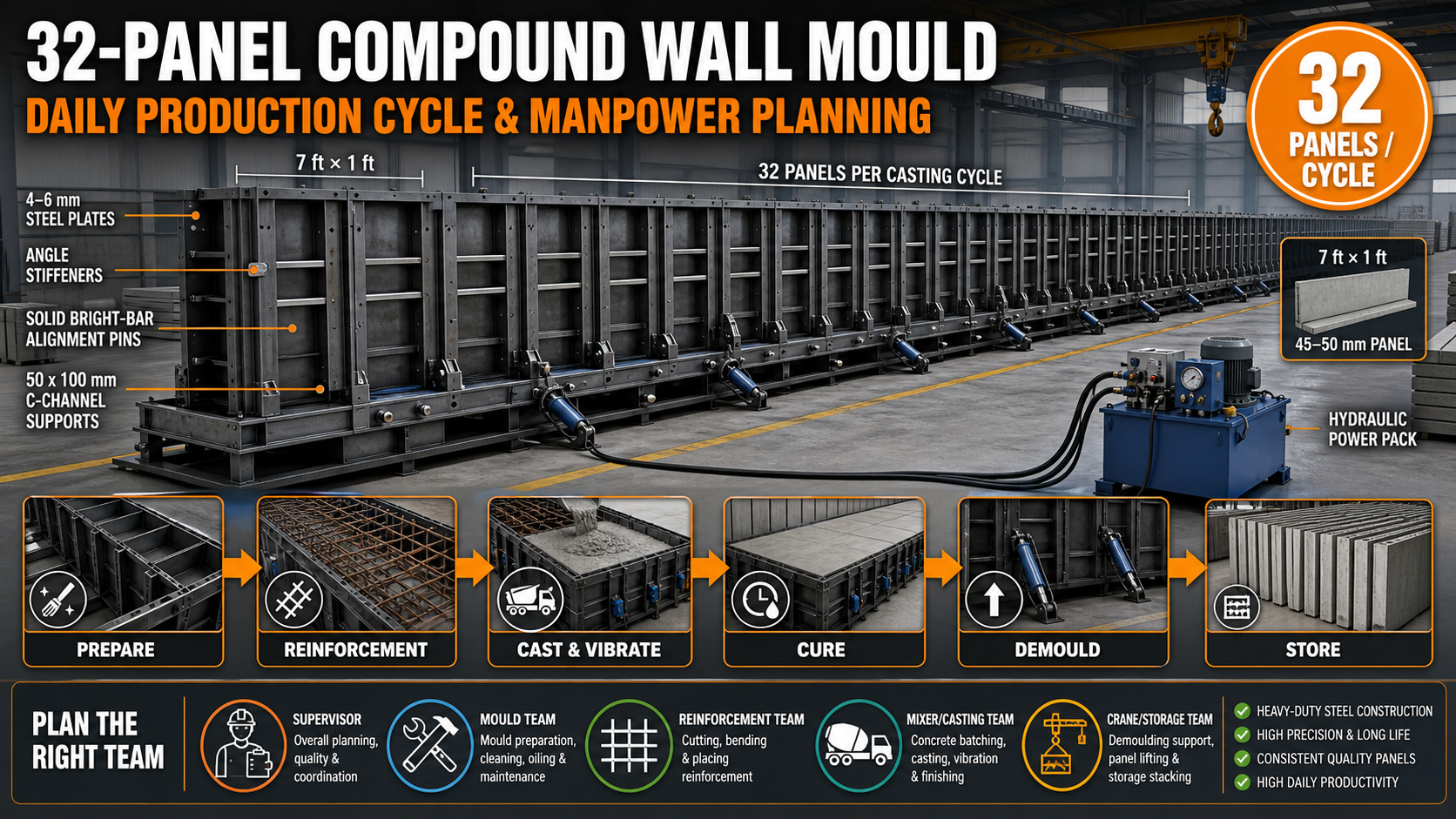
A 32-panel compound wall mould produces an entire batch of precast wall panels in one casting cycle. This guide explains production scheduling, labour allocation, concrete flow, hydraulic operation and daily output planning.
By Paras Steel Industries ·
32-Panel Compound Wall Mould: Daily Production Cycle and Manpower Planning
32-Panel Compound Wall Mould: Daily Production Cycle and Manpower Planning
A high-capacity compound wall mould can significantly improve the production output of a precast boundary wall manufacturing unit.
The Compound Wall Mould manufactured by Paras Steel Industries produces 32 precast wall panels in one line per casting cycle. Its single-line arrangement helps manufacturers use factory space efficiently and meet large residential, agricultural, commercial and infrastructure orders.
However, installing a high-capacity mould alone does not guarantee maximum output. Concrete mixing, reinforcement preparation, mould cleaning, casting, vibration, curing, demoulding and storage must operate according to a coordinated daily schedule.
This guide explains how to organise a 32-panel mould line and plan the required manpower without compromising product quality.
32-Panel Compound Wall Mould Specifications
The standard product configuration listed by Paras Steel Industries includes:
Mould type: Single-line precast panel mould assembly
Production output: 32 panels per line or casting cycle
Standard panel dimensions: 7 ft x 1 ft or approximately 2130 mm x 305 mm
Panel thickness: 45 mm to 50 mm
Main supporting frame: 50 x 100 mm heavy-duty C-channel
Base and side plates: 4 mm to 6 mm high-tensile steel plates
Outer reinforcement: 50 x 50 x 6 mm structural steel angle
Locking and alignment pins: Solid bright steel bar
Operation: Manual or hydraulic-system compatible
Panel sizes, cavity spacing and surface profiles can be customised according to project specifications.
What Is a 32-Panel Compound Wall Mould?
A 32-panel compound wall mould is a high-output steel production line containing multiple accurately spaced panel-forming sections.
The system allows 32 boundary wall panels to be cast within one coordinated mould assembly.
It can manufacture panels for:
• Residential compound walls • Factory perimeter walls • Warehouse boundaries • Commercial complexes • Industrial parks • Agricultural land fencing • Farmhouse enclosures • Housing developments • School and hospital boundaries • Public infrastructure projects
The mould can operate manually or use hydraulic systems for opening, clamping and demoulding.
Benefits of a 32-Panel Mould Line
High Output per Batch
One complete casting cycle produces 32 panels, provided all cavities are prepared and filled correctly.
Efficient Factory-Space Utilisation
A single-line arrangement organises multiple panel cavities within one dedicated production zone.
Consistent Panel Dimensions
Accurate steel plates, alignment pins and locking arrangements help maintain uniform panel length, height and thickness.
Lower Labour per Finished Panel
Workers prepare and operate one coordinated mould line instead of handling several unrelated moulds spread throughout the factory.
Hydraulic Compatibility
Hydraulic opening and clamping can reduce manual handling time and support a faster production cycle.
Custom Panel Requirements
Panel dimensions, surface profiles and cavity arrangements can be manufactured according to project needs.
Understanding the Complete Production Cycle
A mould production cycle includes more than concrete pouring.
The complete cycle consists of:
1. Production planning 2. Mould opening 3. Mould cleaning 4. Dimensional inspection 5. Release-agent application 6. Reinforcement preparation 7. Reinforcement placement 8. Insert installation 9. Mould closing and locking 10. Concrete batching 11. Concrete transportation 12. Concrete pouring 13. Vibration and compaction 14. Surface finishing 15. Curing 16. Strength verification 17. Demoulding 18. Product inspection 19. Panel shifting 20. Mould preparation for the next batch
A delay at any stage can prevent the mould from completing the planned cycle.
Daily Production Capacity Formula
One mould line produces 32 panels per successful casting cycle.
The basic capacity formula is:
Daily Output = Number of Mould Lines × Casting Cycles per Day × 32 Panels
Example:
One mould line completing one casting cycle produces:
1 × 1 × 32 = 32 panels per day
Two mould lines completing one casting cycle each produce:
2 × 1 × 32 = 64 panels per day
If an approved accelerated process permits more than one safe cycle, output can increase accordingly. However, the production schedule must be based on verified concrete strength and actual factory capability.
Do not plan demoulding only according to elapsed time.
Calculate the Required Concrete Volume
The approximate volume of one plain rectangular panel may be calculated as:
Panel Volume = Length × Height × Thickness
Total Concrete Volume = Volume per Panel × 32
The final concrete requirement should also consider:
• Panel surface profile • Grooves • Chamfers • Embedded components • Concrete retained in equipment • Controlled production allowance • Approved product drawing
Use metric units consistently during calculation.
The batching plant or concrete mixer must be able to supply the complete line without excessive delays between cavities.
Daily Production Planning
A practical daily schedule should begin before the mould is ready for concrete.
The reinforcement team, batching team and mould team should work in parallel where possible.
A sample production flow may include:
Previous Shift or Earlier Preparation:
• Prepare reinforcement mesh • Check raw-material stock • Prepare inserts and spacers • Confirm mixer availability • Inspect crane and trolley • Review production drawing
Start of Production Shift:
• Confirm concrete strength of previous batch • Open the mould • Demould finished panels • Shift panels to the curing or storage area • Inspect panel quality • Clean all mould cavities • Check alignment and locks • Apply release agent • Install reinforcement • Close and lock the mould • Complete pre-pour inspection
Casting Stage:
• Batch concrete • Transport concrete to the mould • Fill cavities in the planned sequence • Operate vibration equipment • Observe joints and locks • Finish exposed surfaces • Begin curing
After Casting:
• Clean the mixer and trolley • Record the batch • Inspect the mould externally • Prepare reinforcement for the next cycle • Organise finished-product storage
The exact timing depends on factory layout, curing conditions, concrete supply and level of automation.
Manpower Planning Principles
The correct manpower requirement depends on:
• Manual or hydraulic operation • Factory layout • Distance from mixer to mould • Concrete transportation method • Reinforcement complexity • Crane availability • Panel shifting system • Operator experience • Number of mould lines • Curing method • Daily production target
The goal is to assign enough workers to avoid production bottlenecks without placing unnecessary personnel around the active mould.
Typical Work Teams
1. Production Supervisor
Main responsibilities:
• Confirm production schedule • Verify product drawing • Coordinate all work teams • Check material availability • Approve the pre-pour inspection • Monitor production records • Control the casting sequence
2. Mould Preparation Team
Main responsibilities:
• Open the mould • Clean steel surfaces • Inspect plates and cavities • Check guide pins and locks • Apply release agent • Install gaskets or seals • Close and secure the mould
A hydraulic mould may reduce the physical effort required for opening and closing.
3. Reinforcement Team
Main responsibilities:
• Cut and prepare reinforcement • Assemble panel mesh • Install cover blocks • Position reinforcement • Install lifting inserts • Confirm cage clearance
Preparing reinforcement in advance can shorten mould idle time.
4. Concrete Mixing Team
Main responsibilities:
• Measure raw materials • Operate the mixer • Control water and admixture dosing • Check concrete consistency • Record batch information • Clean mixing equipment
5. Concrete Transportation Team
Main responsibilities:
• Receive concrete from the mixer • Move it to the mould • Control discharge • Prevent concrete loss • Maintain a continuous supply • Clean the shifting trolley or bucket
6. Casting and Vibration Team
Main responsibilities:
• Distribute concrete across cavities • Control filling sequence • Operate vibrators • Monitor divider movement • Watch for slurry leakage • Complete surface finishing
7. Demoulding and Shifting Team
Main responsibilities:
• Confirm demoulding approval • Release locks • Operate hydraulic shutters • Connect lifting equipment • Remove panels • Shift panels to curing or storage • Position panels on suitable supports
8. Quality-Control Inspector
Main responsibilities:
• Check mould dimensions • Inspect reinforcement placement • Review concrete consistency • Confirm strength results • Measure finished panels • Record defects by cavity position
Illustrative Manpower Arrangement
The following is an example only and should be adjusted according to the plant:
• One production supervisor • Two workers for mould cleaning and preparation • Two workers for reinforcement and insert placement • One trained mixer operator • One or two workers for concrete transportation • Two workers for pouring, vibration and finishing • One crane, trolley or hydraulic-system operator • One quality-control person, who may supervise multiple production activities
Some responsibilities can overlap in a compact factory. A larger plant with several mould lines may require separate teams.
Hydraulic automation can reduce opening and closing labour, but it does not eliminate the need for inspection, cleaning, reinforcement, concrete placement and safe panel handling.
How to Reduce Mould Idle Time
Prepare Reinforcement in Advance
The next set of reinforcement should be ready before the previous panels are demoulded.
Maintain Raw-Material Stock
Cement, aggregates, reinforcement, spacers and release agent should be available before production begins.
Position the Mixer Correctly
The mixer should be close enough to the mould line to reduce concrete transport time without blocking crane or worker movement.
Use a Suitable Concrete Shifting Trolley
A trolley with adequate capacity can help maintain a continuous supply of concrete to the 32-panel mould.
Prepare the Storage Area
Finished panels should move directly to prepared supports or racks. Searching for storage space during demoulding wastes production time.
Use Preventive Maintenance
Inspect locks, guide pins, hydraulic cylinders, hoses and vibrator brackets before they fail during casting.
Concrete Filling Sequence
A 32-panel line should be filled in a balanced and controlled sequence.
The process should:
• Avoid overloading one section first • Maintain consistent concrete workability • Reduce long delays between cavities • Prevent reinforcement movement • Control pressure on shutters • Allow proper vibration • Maintain equal panel quality
The exact sequence should be established during trial production.
Operators should record which filling sequence produces the best consistency.
Concrete Supply Planning
The mixer should provide concrete at a rate matching mould filling and vibration.
Concrete delivered too slowly can cause:
• Cold joints • Variation in finish • Inconsistent workability • Extended casting time • Reduced productivity
Concrete delivered too quickly can cause:
• Congestion • Uncontrolled filling • Mould pressure imbalance • Concrete waste • Insufficient vibration
Coordinate mixing, transport and casting instead of allowing each team to work independently.
Vibration Planning
The mould can be designed for a suitable external or shutter-vibration arrangement.
Vibration should be applied uniformly along the production line.
Check:
• Vibrator type • Mounting position • Operating duration • Electrical connections • Fastener condition • Effect on locks and alignment
Insufficient vibration may cause honeycombing. Excessive vibration may cause segregation, slurry leakage and reinforcement movement.
Hydraulic Operation and Labour Saving
A hydraulic system can assist with:
• Outer-shutter opening • Shutter closing • Clamping • Controlled demoulding • Faster mould preparation
Before operation, inspect:
• Hydraulic oil level • Power pack • Hoses and fittings • Cylinder rods • Mounting pins • Control valves • Mechanical locks • Visible leakage • Emergency controls
Hydraulic cylinders should move shutters gradually and evenly.
Workers must remain clear of pinch points and moving components.
Hydraulic pressure should not be used to force open a mould that remains mechanically locked or bonded to the concrete.
Pre-Pour Inspection
Before casting, confirm:
• All 32 panel sections are clean • Panel dimensions are correct • Steel plates remain straight • Guide pins are engaged • Reinforcement is positioned correctly • Concrete cover is maintained • Release agent is applied uniformly • Hydraulic shutters are closed • Mechanical locks are engaged • Joints are properly sealed • Vibrators are secured • Concrete supply is ready • Production drawing is available
The supervisor or quality-control inspector should record the inspection.
Curing and Demoulding Planning
The next production cycle depends on the time required to achieve approved demoulding strength.
Strength development depends on:
• Concrete mix design • Cement type • Temperature • Panel thickness • Curing method • Workability • Compaction quality
Panels should not be removed merely because a fixed number of hours has passed.
Concrete strength should be verified according to the approved quality procedure.
Panel Demoulding Process
A controlled demoulding sequence may include:
1. Confirm approved stripping strength. 2. Clear the work area. 3. Prepare panel-shifting equipment. 4. Release mechanical locks gradually. 5. Operate hydraulic shutters slowly. 6. Check that panels have separated. 7. Connect approved lifting equipment. 8. Remove one panel at a time. 9. Place panels on suitable supports. 10. Inspect dimensions and finish. 11. Continue curing. 12. Clean the mould immediately.
Do not stack newly demoulded panels without an approved support arrangement.
Finished-Product Storage Planning
A 32-panel mould produces a complete group of panels in each batch. The storage area must be ready to receive them.
Plan for:
• Stable panel racks or supports • Product identification • Casting-date marking • Safe crane access • Continued curing • Quality-inspection status • First-in, first-out dispatch • Separation of rejected products
Storage capacity should be calculated according to daily output and average dispatch time.
Example:
If one line produces 32 panels per day and panels remain in the yard for five days, storage may need to accommodate at least 160 panels, plus a practical operational allowance.
Quality Control by Cavity Number
Assign a number to every panel-forming location.
If a defect appears, record its cavity number.
This helps identify:
• Bent plate • Worn alignment pin • Loose lock • Damaged seal • Inadequate vibration location • Incorrect divider spacing • Repeated slurry leakage
Cavity-based records make maintenance faster and more targeted.
Common Production Bottlenecks
Reinforcement Not Ready
The mould remains empty while workers prepare mesh.
Insufficient Concrete Mixer Capacity
The complete line takes too long to fill.
Slow Concrete Transportation
The mixer produces concrete faster than the trolley can deliver it.
Inadequate Crane Availability
Finished panels cannot be removed because the crane is occupied elsewhere.
Unprepared Storage Area
Demoulded panels block the production line.
Manual Opening of Large Shutters
Opening and closing may consume excessive labour and time.
Poor Mould Cleaning
Hardened concrete causes joint gaps and dimensional variation.
Hydraulic Breakdown
Damaged hoses or cylinders can stop the entire production cycle.
Daily Maintenance Checklist
Before Production:
• Inspect main frame • Clean steel plates • Check bright-bar alignment pins • Inspect locks • Check hydraulic oil • Inspect hoses and cylinders • Check vibrator mounts • Verify panel dimensions • Prepare reinforcement and inserts
After Casting:
• Clean spilled concrete • Inspect joints for leakage • Check locks for movement • Clean mixer and trolley • Record concrete batch • Prepare reinforcement for the next cycle
After Demoulding:
• Clean all casting surfaces • Inspect every cavity • Check panels for repeated defects • Lubricate suitable moving parts • Inspect hydraulic components • Record maintenance requirements
How to Calculate Labour Productivity
A useful measurement is:
Labour Hours per Panel = Total Direct Labour Hours ÷ Number of Accepted Panels
Example:
If the production team uses 72 direct labour hours to produce 32 accepted panels:
72 ÷ 32 = 2.25 labour hours per accepted panel
This is only an illustrative calculation.
The plant should monitor its own results and compare:
• Manual and hydraulic cycles • Different team sizes • Casting duration • Cleaning duration • Rejection rate • Overtime • Accepted output
The lowest labour hours are not automatically the best result if product defects increase.
Manual vs Hydraulic Production Planning
Manual Operation May Suit:
• Moderate production targets • Lower initial investment • Plants with sufficient labour • Simple maintenance capability
Hydraulic Operation May Suit:
• Continuous high-volume production • Faster shutter operation • Reduced manual effort • Large-scale boundary wall projects • Plants seeking repeatable cycle times
The decision should consider investment, maintenance, labour cost and expected production volume.
Buying Checklist
Before ordering a 32-panel Compound Wall Mould, confirm:
• Required panel dimensions • Panel thickness • Surface profile • Number of panels per batch • Steel plate thickness • Main C-channel size • Structural-angle size • Locking-pin material • Manual or hydraulic operation • Concrete mixer capacity • Vibration method • Crane capacity • Factory floor space • Storage capacity • Daily production target • Custom design requirements
Final Conclusion
A 32-panel Compound Wall Mould can produce a complete high-volume batch of precast wall panels in one casting cycle.
The standard system from Paras Steel Industries produces 32 panels measuring approximately 7 ft x 1 ft, with a thickness range of 45 mm to 50 mm.
Its main structure uses 50 x 100 mm heavy-duty C-channels, 4 mm to 6 mm high-tensile steel plates, 50 x 50 x 6 mm structural angles and solid bright-steel alignment pins.
Maximum output depends on more than mould capacity. Reinforcement, concrete mixing, transportation, casting, vibration, curing, demoulding and storage must operate as one coordinated production system.
Hydraulic opening and clamping can reduce manual effort and shorten selected production activities. Proper manpower planning ensures that labour is available at each critical stage without creating congestion around the mould.
For a customised quotation, share your panel dimensions, surface design, daily production target, available manpower, factory layout and preferred manual or hydraulic system with Paras Steel Industries.