
Precast Mould Maintenance Guide
32-Panel Compound Wall Mould End-Shutter Alignment: Panel Length, Joint Gaps and Locking Guide
End shutters establish the casting length and close the outer ends of a 32-panel compound wall mould. Incorrect positioning, uneven joint gaps or loose locking can produce inconsistent panel lengths, concrete fins and slurry leakage. This guide explains end-shutter inspection, alignment, sealing and locking for heavy-duty iron compound wall moulds.
By Paras Steel Industries ·
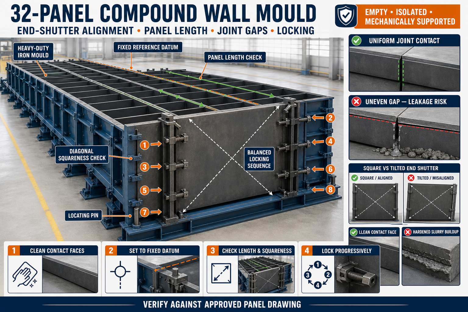
32-Panel Compound Wall Mould End-Shutter Alignment: Panel Length, Joint Gaps and Locking Guide
32-Panel Compound Wall Mould End-Shutter Alignment: Panel Length, Joint Gaps and Locking Guide
A 32-panel compound wall mould produces multiple precast boundary wall panels in one casting cycle. Every cavity must remain correctly positioned to achieve consistent panel dimensions and reliable installation at the project site.
The end shutters close the outer ends of the casting arrangement and help establish the required panel length. If an end shutter is tilted, displaced or inadequately locked, it can affect multiple panels in the same production batch.
Accurate end-shutter alignment helps control panel length, joint tightness, concrete finish and slurry leakage.
What Is an End Shutter?
An end shutter is a removable or hinged iron component installed at the end of a compound wall mould. It closes the mould cavities and contains fresh concrete during casting and vibration.
Depending on the mould design, an end-shutter assembly may include:
• Heavy-duty iron or steel plate • Structural stiffeners • Alignment guides • Locating pins • Hinges or removable mounting points • Wedge locks or screw clamps • Sealing strips • Contact faces • Mechanical stops • Lifting or handling points
The exact construction depends on the panel profile, mould configuration and operating system.
Role of the End Shutter in Panel Production
The end shutter performs several important functions:
• Establishes the required panel length • Closes all cavities at the mould end • Prevents concrete and slurry leakage • Maintains square panel ends • Supports consistent tongue, groove or edge profiles • Resists concrete pressure during filling • Helps maintain alignment during vibration • Supports repeatable production across casting cycles
A small alignment error at the end shutter may be repeated across several cavities.
How End-Shutter Misalignment Affects Panel Quality
An incorrectly aligned shutter can cause:
• Different panel lengths • Out-of-square panel ends • Uneven joint gaps • Concrete fins • Slurry leakage • Damaged panel edges • Incorrect tongue-and-groove profiles • Difficulty during boundary wall installation • Uneven stacking • Increased rejection and repair work
Repeated dimensional errors should be investigated at the mould rather than corrected only on the finished panels.
Common Causes of End-Shutter Misalignment
End-shutter alignment may change due to:
• Concrete buildup on contact faces • Hardened slurry around locating points • Worn hinges or bushes • Bent locating pins • Loose locking brackets • Unevenly adjusted clamps • Distorted shutter plates • Damaged sealing strips • Impact during handling • Mould-bed movement • Incorrect divider positioning • Overloaded or damaged structural stiffeners • Failure to clean the mould after casting
Inspection should cover the complete shutter system, not just the visible joint.
Preparing the Mould for Alignment
Before beginning alignment work:
• Stop the casting operation • Isolate hydraulic or powered equipment • Release stored pressure safely • Mechanically support movable components • Clean the mould completely • Remove concrete from contact faces • Inspect hinges, guides and locating pins • Keep measuring tools ready • Follow the mould manufacturer’s procedure
Never perform alignment work while shutters are moving or supported only by hydraulic pressure.
Establish a Fixed Reference Datum
End-shutter alignment should be checked from a fixed mould reference.
Possible reference points include:
• Main mould centreline • Fixed base frame • Machined datum face • Approved reference stop • Verified divider position • Mould-bed reference line
Do not measure only from a movable or unverified component because this can transfer an existing error to the end shutter.
Checking Panel Length
Panel length should be checked at more than one location.
A practical inspection may include:
• Measurement along the upper part of the cavity • Measurement along the lower part of the cavity • Comparison between corresponding cavities • Checking both sides of the mould • Confirmation against the approved product drawing
If the upper and lower readings differ, the end shutter may be tilted.
All final dimensions and tolerances should follow the approved panel drawing and project requirements.
Checking End-Shutter Squareness
A square end shutter helps produce consistent panel ends.
Squareness can be checked by:
• Comparing diagonal measurements • Using an approved engineer’s square • Checking the shutter against verified mould reference lines • Measuring the cavity length at multiple heights • Inspecting contact across the complete shutter face
Do not use the floor or an unverified structural surface as the only reference.
Understanding Joint Gaps
A joint gap is the clearance between the end shutter and the adjoining mould surface.
An uneven gap can allow cement slurry to escape during casting and vibration. It may also create a concrete fin along the finished panel edge.
Check joint gaps:
• At the top of the shutter • At the bottom • Along both sides • Around profile inserts • Near hinge points • Around locking locations • Across all affected cavities
The contact should remain consistent without forcing the shutter into distortion.
Why Joint Gaps Develop
Common reasons include:
• Slurry trapped on the contact face • Worn hinge pins or bushes • Unequal lock adjustment • Bent end-shutter plate • Misaligned base frame • Damaged sealing strip • Loose locating pin • Excessive welding distortion after repair • Foreign material between mating faces • Shutter sag caused by inadequate support
Closing the locks more tightly may not correct the root cause.
End-Shutter Locking Systems
A 32-panel compound wall mould may use:
• Wedge locks • Screw clamps • Toggle clamps • Pin-and-slot locks • Hydraulic locking arrangements • Bolted connections • Combination locking systems
The locking system should pull the shutter evenly against its contact faces without bending the plate or disturbing cavity alignment.
Correct Locking Sequence
The exact locking sequence depends on the mould design. A general controlled procedure may include:
1. Clean the Contact Faces
Remove concrete, slurry, rust flakes and other contaminants.
2. Move the Shutter Into Position
Close or place the end shutter carefully without impact.
3. Engage Locating Components
Confirm that guide pins, stops or alignment blocks are seated correctly.
4. Apply Initial Locking
Engage the central or primary locks lightly to hold the shutter.
5. Check Position
Verify panel length, squareness and joint consistency.
6. Tighten Locks Progressively
Apply the remaining locks in a balanced sequence.
7. Recheck Alignment
Confirm that tightening has not pulled the shutter out of position.
8. Perform a Final Pre-Pour Inspection
Check every lock, cavity and sealing point before concrete filling begins.
Avoid fully tightening one side while the other side remains open.
How to Check Locking Pressure
Locks should hold the shutter securely but should not distort it.
Warning signs of incorrect locking include:
• One lock requires much more force than others • The shutter shifts during tightening • The plate bends around a lock • The upper and lower joint gaps change • Locks loosen during vibration • Wedges seat differently across the shutter • Contact remains incomplete after tightening
Do not use excessive hammering or improvised extensions to create additional locking force.
Preventing Slurry Leakage
To reduce leakage at the end shutter:
• Keep mating surfaces clean and flat • Repair damaged shutter edges • Maintain hinges and locating pins • Adjust locks evenly • Replace worn seals with approved components • Check the shutter before every pour • Avoid excessive or uncontrolled vibration • Confirm that no reinforcement obstructs closure • Inspect profile inserts and corner joints • Repair recurring gaps at their source
Improvised packing should not replace correct mechanical alignment.
Inspecting End-Shutter Stiffeners
End shutters require sufficient structural stiffness to resist fresh concrete pressure and vibration.
Inspect stiffeners for:
• Bent channels or angles • Cracked welds • Loose connections • Local plate bulging • Corrosion • Previous repair distortion • Damaged lock brackets • Separation between plate and stiffener
Repairs should restore the approved geometry without introducing additional heat distortion.
Relationship Between Dividers and End Shutters
Divider alignment and end-shutter alignment are connected.
If a divider is displaced:
• Panel spacing may change • A cavity may not meet the end shutter correctly • Joint gaps can develop • Panel thickness may vary • Locking force may become uneven • Slurry may pass between adjoining cavities
Check the divider arrangement before making major end-shutter adjustments.
Pre-Pour End-Shutter Inspection Checklist
Before placing concrete, confirm:
• End shutter is installed in the correct orientation • Contact surfaces are clean • Panel length matches the approved drawing • Shutter is square to the mould • Upper and lower measurements are consistent • Locating pins are fully seated • All locks are engaged • Joint gaps are controlled • Seals are correctly positioned • Reinforcement does not obstruct closure • Profile inserts are aligned • No tools or foreign objects remain inside the mould • Hydraulic components are in the approved operating condition
Record the inspection where required by the factory quality procedure.
Checks During Concrete Casting
During casting, observe the mould from a safe position.
Look for:
• Fresh slurry at shutter joints • Movement of locks • Shutter vibration • Local plate bulging • Change in joint gaps • Concrete spilling from the mould end • Unusual noise • Movement of the complete mould frame
Stop the process safely if significant movement or leakage is observed.
Demoulding the End Shutter
The end shutter should be opened only after the concrete has achieved sufficient demoulding strength.
A general demoulding sequence includes:
• Support the precast panels • Remove concrete buildup around locks • Release locks progressively • Keep personnel clear of pinch points • Open the shutter without sudden impact • Protect fresh panel corners • Inspect the shutter contact face • Clean the shutter immediately
Do not pull the shutter against concrete that remains mechanically locked to it.
End-Shutter Maintenance Checklist
After each production cycle:
• Remove concrete and slurry • Clean sealing surfaces • Inspect locating pins • Check hinges and bushes • Inspect lock wear • Lubricate approved moving points • Examine welds and stiffeners • Check the shutter for bending • Inspect sealing strips • Confirm smooth opening and closing • Apply corrosion protection during storage • Record recurring alignment problems
Routine maintenance is easier and less expensive than correcting distorted mould components after repeated production.
Common End-Shutter Alignment Mistakes
Measuring From an Unverified Surface
Measurements may appear consistent while the complete shutter remains incorrectly positioned.
Tightening Locks Before Alignment
Fully tightening the locks too early can pull the shutter away from its correct datum.
Ignoring Concrete Buildup
A thin layer of hardened concrete can create a measurable joint gap.
Using Excessive Locking Force
High force may bend the shutter or damage the locking brackets.
Checking Only One Cavity
A shutter can be correct at one location and misaligned across other cavities.
Ignoring Worn Hinges
Hinge wear can allow the shutter to sag and produce different upper and lower gaps.
Correcting Finished Panels Instead of the Mould
Repeated grinding or repair of panels does not solve the original alignment problem.
Troubleshooting Common Problems
Problem: Panels Have Different Lengths
Possible causes:
• End shutter is tilted • Dividers are displaced • Reference stop has moved • Locks are pulling unevenly • Contact faces contain hardened concrete
Problem: Slurry Leaks From One Corner
Possible causes:
• Local joint gap • Damaged sealing strip • Bent shutter corner • Weak or misadjusted lock • Concrete buildup on the mating face
Problem: Shutter Opens With Difficulty
Possible causes:
• Concrete has bonded to the shutter • Locks are not fully released • Hinge pins are worn or seized • Shutter is distorted • Concrete fins are holding the joint
Problem: Locks Loosen During Vibration
Possible causes:
• Worn wedge surfaces • Damaged lock brackets • Incorrect adjustment • Excessive vibration • Shutter movement caused by poor alignment
Problem: Panel Ends Are Not Square
Possible causes:
• End shutter is out of square • Mould base is twisted • Shutter plate is bent • Divider positions are inconsistent • Locking sequence is unbalanced
Benefits of Accurate End-Shutter Alignment
Proper alignment provides:
• Consistent panel length • Square and clean panel ends • Reduced slurry leakage • Fewer concrete fins • Better panel stacking • Easier boundary wall installation • Reduced rejection and repair • More reliable multi-panel production • Longer mould and lock service life • Improved production efficiency
Conclusion
End-shutter alignment is essential for reliable operation of a 32-panel compound wall mould. The shutter must close against verified reference points while maintaining consistent panel length, squareness and joint contact across all cavities.
Correct cleaning, measurement, progressive locking and routine maintenance can prevent slurry leakage, concrete fins and dimensional variation. Operators should also inspect the dividers, hinges, locating pins, seals and structural stiffeners because these components directly affect end-shutter performance.
A correctly aligned heavy-duty iron compound wall mould helps manufacturers produce uniform precast panels with accurate lengths, clean edges and dependable installation quality.