
Precast Mould Guide
32-Panel Compound Wall Mould Divider Alignment: Equal Panel Thickness, Spacing and Slurry Control
Accurate divider alignment is essential in a 32-panel compound wall mould because one displaced divider can affect several concrete panels. This guide explains fixed-datum spacing, thickness checks, divider locking and slurry-leakage control.
By Paras Steel Industries ·
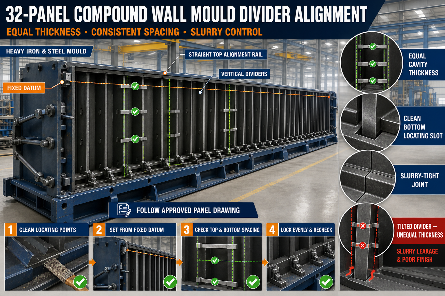
32-Panel Compound Wall Mould Divider Alignment: Equal Panel Thickness, Spacing and Slurry Control
32-Panel Compound Wall Mould Divider Alignment Guide
A 32-panel compound wall mould is designed for high-output precast wall panel production. Multiple panels are cast within one heavy-duty iron mould line, helping manufacturers increase daily output and use factory space efficiently.
The accuracy of every panel depends on the position of the internal dividers. If one divider bends, shifts or is installed incorrectly, the neighbouring panel cavities may develop unequal thickness, incorrect spacing or slurry leakage.
This guide explains compound wall mould divider alignment, including fixed-datum measurement, equal panel thickness, divider spacing, locking and slurry control.
What Is a Compound Wall Mould Divider?
A divider is an iron or structural-steel component that separates one panel-casting cavity from the next. It helps form the panel faces, edges and required thickness.
A divider assembly may include:
• Heavy iron divider plate • Structural stiffeners • Alignment pins • Bottom locating points • Top alignment channel • Spacers • Locking clamps • Wedges or bolts • Flange-contact surfaces • Sealing strips where required • Lifting or handling points
The exact divider design depends on the panel profile and approved mould drawing.
Why Divider Alignment Is Important
In a multi-panel mould, each divider forms one side of one panel and the opposite side of the neighbouring panel. Therefore, a single alignment error can affect two cavities.
Correct divider alignment helps achieve:
• Equal panel thickness • Consistent cavity spacing • Straight panel faces • Uniform panel edges • Better joint fit during installation • Controlled slurry leakage • Easier demoulding • Consistent embossed patterns • Repeatable production quality • Reduced panel rejection
Divider alignment should be checked before every casting cycle.
Common Divider Alignment Problems
Typical problems include:
• Divider leaning to one side • Unequal cavity width • Divider not seated at the bottom • Top and bottom positions not matching • Bent divider plate • Loose locking points • Concrete buildup at locating slots • Damaged alignment pins • Worn spacers • Gaps at divider joints • Pattern liners not matching • Slurry leaking between cavities
These problems should be corrected before reinforcement and concrete are placed.
Safety Before Alignment Work
A divider can be large and heavy. It must be handled using approved equipment and lifting points.
Before beginning:
1. Stop nearby mould operation. 2. Clean and isolate the working area. 3. Confirm the divider weight and lifting method. 4. Inspect lifting equipment. 5. Use only approved lifting points. 6. Keep personnel away from suspended components. 7. Place the divider on stable supports. 8. Wear appropriate personal protective equipment. 9. Never place hands between an unsupported divider and mould frame.
Do not use locking handles, sealing brackets or random welded parts as lifting points.
Clean the Mould Before Checking Alignment
Hardened concrete or slurry beneath a divider can change its position.
Clean:
• Bottom locating channel • Divider contact surfaces • Alignment-pin holes • Top guide channel • Side flanges • Locking points • Spacers • Sealing grooves • Pattern-liner edges • Base casting surface
Alignment measurements should only be taken after all contact areas are clean.
Establish a Fixed Datum
A fixed datum is a permanent reference point used to position every divider. It helps prevent accumulated measurement errors.
The datum may be established from:
• One mould end frame • A fixed base-frame reference • A marked centreline • A dedicated alignment rail • An approved survey point
Every divider position should be checked from the same datum.
Avoid Cumulative Measurement
Do not position the second divider only from the first divider, the third from the second and continue in the same manner. Small errors can accumulate across a 32-panel mould.
Instead:
• Mark every divider position from the fixed datum • Use a verified template or gauge • Check selected positions using an independent reference • Record the measurements • Recheck the last cavity against the mould end frame
This method helps maintain consistent spacing throughout the complete line.
Inspect the Mould Base
Divider alignment depends on a stable and level mould base.
Check:
• Base-frame level • Longitudinal straightness • Crosswise level • Support contact • Anchor condition • Structural distortion • Welded joints • Concrete buildup beneath the frame • Modular-section alignment
A twisted base can make correctly manufactured dividers appear misaligned.
Check Divider Straightness
Before installation, inspect every divider for:
• Longitudinal bowing • Sideways bending • Twisting • Local plate deformation • Damaged edges • Cracked welds • Bent stiffeners • Worn locating points • Corrosion • Impact damage
Use a suitable straightedge, template or survey method according to the divider size and required accuracy.
Bottom Divider Alignment
The bottom locating system establishes the divider’s basic position.
During installation:
1. Clean the locating slot or base reference. 2. Lower the divider slowly. 3. Confirm full seating at both ends. 4. Check that no debris remains underneath. 5. Engage the locating pins or stops. 6. Verify the bottom position from the fixed datum. 7. Install temporary support where required. 8. Do not fully tighten locks yet.
A divider that is not fully seated can create incorrect panel thickness and slurry leakage.
Top Divider Alignment
The top guide keeps the divider vertical and maintains spacing.
Check:
• Divider position in the top channel • Top spacer condition • Pin engagement • Clearance at both ends • Top-to-bottom alignment • Guide-rail straightness • Locking-bracket position
The top should not be forced into position if the bottom remains misaligned.
Check Divider Verticality
A leaning divider creates different cavity widths at the top and bottom.
Check verticality:
• At both ends of the divider • Near the centre • Along both divider faces • Before locking • After initial locking • After final tightening
Use an appropriate level, plumb reference, laser or approved checking fixture.
Equal Panel Thickness Check
Panel thickness is determined by the space between adjacent divider faces or between a divider and shutter.
Check cavity thickness:
• At the top • At the bottom • At both ends • Near the centre • Around patterned or embossed areas • Near modular joints • After locking all dividers
The required thickness must follow the approved panel drawing.
Use a Thickness Gauge or Template
A rigid approved template can make cavity checks faster and more repeatable.
The gauge should:
• Match the approved cavity requirement • Be clearly identified • Remain straight and undamaged • Be checked periodically • Fit without forcing • Be used at fixed inspection points • Be stored safely after use
Do not use a damaged measuring template.
Divider Spacing Check
Spacing should remain consistent throughout the 32-panel mould line.
A practical spacing procedure includes:
1. Establish the fixed datum. 2. Mark every divider location. 3. Position all dividers loosely. 4. Check the first and last cavity. 5. Measure selected intermediate cavities. 6. Verify top and bottom spacing. 7. Correct any accumulated error. 8. Tighten dividers gradually. 9. Repeat the complete inspection.
Final values should comply with the approved mould drawing and quality plan.
Check Diagonal Alignment
Diagonal checks can help identify divider twist or cavity squareness problems.
Compare the approved diagonal references at:
• End cavities • Selected intermediate cavities • Modular mould joints • Repaired divider locations • Areas showing previous panel defects
The inspection method should suit the mould design.
Divider Locking Sequence
Locks should be tightened gradually. Fully tightening one divider before positioning the remaining dividers can pull the alignment rail or base frame out of position.
A suitable sequence is:
1. Position every divider loosely. 2. Engage the bottom locating points. 3. Align the top guides. 4. Check cavity thickness. 5. Engage all locks lightly. 6. Tighten opposing locks gradually. 7. Work in a balanced sequence. 8. Recheck spacing and verticality. 9. Complete final tightening. 10. Mark inspected locking points where required.
Locks must secure the dividers without bending them.
Avoid Over-Tightening
Excessive lock pressure can:
• Bend divider plates • Distort top channels • Damage sealing material • Pull locating pins out of alignment • Create unequal cavity spacing • Make demoulding difficult
Use the approved tightening method and locking arrangement.
Slurry Leakage Between Dividers
Concrete slurry can pass through small gaps around divider joints. Leakage may create fins, surface defects and variation between panels.
Common leakage locations include:
• Bottom divider joint • End-flange contact • Modular joints • Worn gasket grooves • Damaged corners • Misaligned divider edges • Locking points • Pattern-liner joints
Identify and repair the source rather than only removing the concrete fin after casting.
Clean Flange-Contact Surfaces
Even a small piece of hardened concrete can prevent complete divider closure.
Before assembly:
• Scrape off hardened slurry carefully • Clean both mating surfaces • Inspect for dents or burrs • Remove loose rust • Check flange straightness • Confirm full surface contact • Keep sealing grooves clean
Do not damage precision contact surfaces with uncontrolled hammering.
Inspect Sealing Materials
Where sealing strips or gaskets are used, inspect them for:
• Cracks • Hardening • Flattening • Cuts • Missing sections • Concrete contamination • Incorrect positioning • Uneven compression • Oil contamination
Use only compatible sealing material according to the mould design.
Temporary Slurry-Sealing Methods
Any temporary sealing method should be approved for precast production.
It must not:
• Change cavity dimensions • Contaminate the concrete • Block reinforcement cover • Create visible surface defects • Interfere with demoulding • Damage the iron mould
Permanent alignment and joint repairs are preferable to repeated temporary sealing.
Reinforcement Placement
After divider alignment, reinforcement should be placed without disturbing the mould setup.
Check:
• Reinforcement position • Required concrete cover • Spacer stability • Lifting inserts • Connection inserts • Reinforcement clearance from dividers • Cage alignment • Embedded-component locations
Reinforcement must not push a divider sideways or prevent the cavity from closing correctly.
Mould-Release Agent Application
Apply a suitable mould-release agent uniformly to the clean iron casting surfaces.
The release agent should be:
• Suitable for precast concrete • Applied in a thin layer • Prevented from pooling • Kept away from required reinforcement bond areas • Compatible with liners and seals • Used according to its manufacturer’s instructions
Excessive application may cause stains, pinholes or an uneven surface finish.
Pre-Casting Inspection
Before pouring concrete, verify:
• Mould-base level • All divider positions • Fixed-datum references • Top and bottom spacing • Divider verticality • Cavity thickness • Lock engagement • Flange closure • Sealing-strip condition • Reinforcement position • Insert locations • Casting-surface cleanliness • Release-agent application
Record the completed inspection according to the plant’s quality-control procedure.
Concrete Placement Sequence
In a 32-panel compound wall mould, concrete should be placed in a planned and balanced sequence.
During casting:
• Distribute concrete evenly • Avoid filling one area excessively before others • Monitor divider movement • Check locking points • Control the filling rate • Avoid uncontrolled concrete impact • Stop if a divider moves • Observe slurry-leakage locations
The placement sequence should follow the mould design and production plan.
Controlled Vibration
Vibration helps compact concrete but can also expose loose dividers and leaking joints.
During vibration:
• Use the approved vibration system • Maintain balanced vibration • Avoid excessive vibration • Monitor divider locks • Observe mould movement • Check for slurry leakage • Stop if abnormal noise appears • Prevent the vibrator from striking divider plates directly
Excessive vibration may cause segregation, leakage and movement of reinforcement.
Divider Inspection During Casting
Operators should observe accessible reference points during concrete placement.
Watch for:
• Divider movement • Changing top gaps • Loose locks • Slurry flow • Abnormal shutter movement • Frame vibration • Reinforcement displacement
Do not enter unsafe areas or adjust loaded dividers without an approved procedure.
Demoulding Sequence
Dividers should be released only after the concrete achieves the required stripping strength.
A controlled process includes:
1. Remove slurry from locks and joints. 2. Support heavy divider components. 3. Release locks gradually. 4. Follow the approved demoulding sequence. 5. Avoid pulling a divider sideways. 6. Protect panel edges. 7. Use designated lifting points. 8. Place dividers on stable supports. 9. Inspect the finished panels. 10. Clean the mould before the next cycle.
Never force a stuck divider using uncontrolled lifting or hammering.
Common Problems and Corrective Actions
Unequal Panel Thickness
Check divider verticality, fixed-datum spacing, worn locating points, loose locks and reinforcement interference.
Divider Leans After Locking
Inspect the tightening sequence, top guide, bottom seating and locking pressure.
Slurry Leaks at the Bottom
Clean the base joint, check full divider seating, inspect sealing material and verify base flatness.
Panel Has a Concrete Fin
Check for gaps, damaged flange edges, hardened slurry or uneven lock pressure.
Spacing Error Increases Along the Line
The dividers may have been positioned cumulatively. Re-establish every location from the fixed datum.
Divider Is Difficult to Remove
Check concrete strength, release-agent application, joint cleanliness, shutter sequence and unintended slurry entry.
Repeated Divider Bowing
Inspect stiffener condition, concrete pressure, vibration, locking arrangement and divider-plate damage.
Post-Demoulding Panel Checks
Inspect panels from different positions in the mould line.
Check:
• Panel thickness • Length and width • Edge straightness • Surface finish • Pattern alignment • Joint profile • Cracks • Honeycombing • Concrete fins • Insert position
Recording the cavity number for each panel can help identify a specific divider or mould location causing repeated defects.
Maintenance of Iron Dividers
Regular maintenance should include:
• Cleaning after every casting cycle • Removing slurry from locating points • Inspecting divider straightness • Lubricating pins and locks • Checking welded stiffeners • Repairing damaged flange edges • Protecting iron surfaces from corrosion • Replacing damaged seals • Recording divider identification • Storing removed dividers on stable supports
Do not store long dividers directly on uneven ground.
When Should Production Be Stopped?
Stop production if you find:
• Severely bent dividers • Broken locking components • Cracked structural welds • Damaged lifting points • Divider movement during casting • Major slurry leakage • Incorrect cavity spacing • Failed locating pins • Unstable mould supports • Inability to maintain panel thickness
Production should resume only after correction and dimensional verification.
Conclusion
Accurate divider alignment is essential for maintaining equal panel thickness and consistent spacing in a 32-panel compound wall mould.
The most reliable approach is to position every divider from one fixed datum, confirm top and bottom spacing, check verticality and tighten all locks in a balanced sequence. Clean contact surfaces and properly maintained seals help control slurry leakage.
Paras Steel Industries manufactures heavy-duty iron and structural-steel compound wall moulds according to customer requirements and approved drawings. Correct divider alignment and regular inspection help support high-output production with consistent panel quality.