
Precast Mould Guide
Y-Shape Pole Mould Y-Arm Core Alignment: Centreline, Wire-Pin Clearance and Safe Extraction
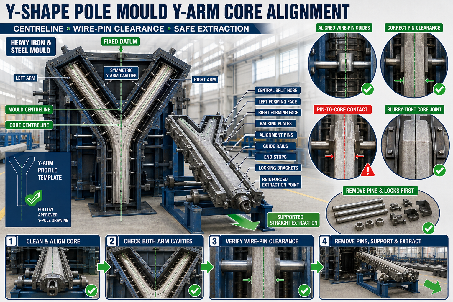
A misaligned Y-arm core can produce unequal security arms, displaced wire holes and difficult demoulding. This guide explains fixed-datum centring, wire-pin clearance, balanced locking and safe core extraction.
By Paras Steel Industries ·
Y-Shape Pole Mould Y-Arm Core Alignment: Centreline, Wire-Pin Clearance and Safe Extraction
Y-Shape Pole Mould Y-Arm Core Alignment Guide
Precast Y-shape concrete poles are used for security fencing around industrial plants, substations, airports, warehouses, solar projects and other restricted areas.
The upper section of the pole divides into two arms that support barbed wire or another approved fencing arrangement. This profile is formed by a dedicated Y-arm core and correctly positioned wire-hole pins inside a heavy-duty iron mould.
If the core moves away from the mould centreline, the two arms may have different profiles or reinforcement cover. Misalignment can also cause wire pins to contact the core, reinforcement or guide bushes.
This guide explains Y shape pole mould core alignment, including fixed-datum positioning, arm symmetry, wire-pin clearance, locking and safe extraction.
What Is a Y-Arm Core?
A Y-arm core is an iron or structural-steel mould component used to form the internal split and profiles of the two upper pole arms.
A typical Y-arm core system may include:
• Fabricated steel core body • Left and right arm-forming faces • Central nose or split former • Tapered release surfaces • Backing plates • Alignment pins • Locating blocks • Mounting brackets • Locking bolts • End stops • Extraction points • Guide rails • Reinforced pull bracket
The exact profile should follow the approved Y-shape pole drawing.
Purpose of Y-Shape Security Poles
Y-shape poles may support:
• Barbed-wire fencing • Security-wire arrangements • Industrial perimeter fencing • Agricultural fencing • Utility and substation fencing • Airport boundary protection • Solar-project fencing • Custom security systems
Wire-hole positions and arm geometry depend on the approved project design.
Why Core Alignment Is Important
Correct core alignment helps maintain:
• Symmetrical Y arms • Pole centreline • Consistent arm thickness • Correct split depth • Balanced concrete cover • Wire-hole position • Reinforcement clearance • Straight pole profile • Easier demoulding • Repeatable production quality
One displaced core can affect several critical upper-pole dimensions.
Common Y-Arm Core Problems
Typical problems include:
• One arm becomes thicker • One arm leans outward • Split depth varies • Y-arm centre shifts • Core twists • Wire pins contact the core • Reinforcement touches the core • Core binds during extraction • Concrete fins form around joints • Arm corners chip during demoulding • Locks do not align • Core pulling bracket bends
These problems should be corrected before concrete placement.
Safety Before Core Setup
The Y-arm core may be heavy and awkward to handle.
Before setup:
1. Stop nearby mould operations. 2. Isolate hydraulic or powered systems. 3. Apply lockout and tagout where required. 4. Position the mould on a stable base. 5. Inspect the approved lifting equipment. 6. Confirm the core’s designated handling points. 7. Keep workers away from suspended components. 8. Support the core before removing fasteners. 9. Keep hands away from pinch points. 10. Wear suitable personal protective equipment.
Do not use wire-pin brackets or locking handles as lifting points.
Inspect the Heavy Iron Mould
Before installing the core, check:
• Mould base • Side shutters • Pole cavity • Y-section borders • Structural stiffeners • Alignment guides • Core brackets • Wire-pin guide bushes • Locks • Hinges • Flange joints • End stops
The mould must be straight and stable before core alignment.
Clean the Mould and Core
Remove:
• Hardened concrete • Slurry • Rust • Old release-agent buildup • Dirt • Burrs • Damaged sealant • Material inside guide holes • Concrete around locating blocks • Debris near the pull path
Measurements should only be taken after cleaning.
Inspect the Y-Arm Core
Check the core for:
• Straightness • Twisting • Bent arm faces • Damaged taper • Cracked welds • Rough surfaces • Corrosion • Concrete buildup • Loose backing plates • Damaged locating pins • Bent extraction bracket • Previous unapproved repairs
A damaged core should not be forced into the mould.
Identify Core Orientation
Mark or identify:
• Top • Bottom • Left arm • Right arm • Mould centreline • Core centreline • Wide and narrow release ends • Pull direction • Core identification • Mould cavity number
Incorrect orientation can reverse the taper or arm profile.
Establish a Fixed Datum
Use one fixed reference for every core measurement.
The datum may be:
• Mould bottom end • Fixed end plate • Mould centreline • Machined stop • Alignment rail • Approved positioning pin
Do not position the core only from movable shutters.
Mark the Mould Centreline
The mould centreline should extend through:
• Main pole section • Y split • Core • Top arm area • End reference • Reinforcement cage
Use a laser, string line, checking bar or approved fixture.
Core Centreline Alignment
Position the core so its centreline coincides with the mould centreline.
Check alignment:
• At the bottom of the Y split • At the central nose • Near the arm ends • At both core guides • Before locking • After final tightening
A core can be centred at one end but twisted at the other.
Y-Arm Symmetry Check
Compare the left and right arm-forming spaces.
Check:
• Arm cavity width • Arm angle according to the drawing • Split depth • Core-to-shutter distance • Arm-end position • Corner profiles • Reinforcement cover zones • Wire-pin positions
Use approved templates without assuming an angle or dimension.
Do Not Align by Visual Appearance Alone
A visually centred core may still have:
• Unequal arm cavities • Twist • Different taper contact • Misaligned wire-pin passages • Unequal reinforcement clearance • Incorrect split depth
Use fixed gauges and reference points.
Check Core Verticality and Twist
Use an approved level, laser or alignment fixture.
Check:
• Core face alignment • Left and right arm faces • Top-to-bottom position • End-to-end straightness • Relationship with the mould base • Guide contact • Pull-axis alignment
Correct twist before installing wire pins.
Y-Arm Profile Template
An approved profile template can help verify:
• Core centre • Arm symmetry • Split depth • Arm opening • Corner transitions • Taper direction • Relationship with outer shutters
The template should be clearly identified and protected from damage.
Dry-Fit the Core
Before reinforcement and concrete placement:
1. Clean the mould. 2. Establish the fixed datum. 3. Position the core. 4. Engage locating pins. 5. Install fasteners loosely. 6. Align the centrelines. 7. Check both arm cavities. 8. Verify wire-pin clearances. 9. Confirm the pull direction. 10. Lock the core gradually. 11. Recheck all measurements.
Do not force bolts through misaligned holes.
Core Locking Sequence
Use a balanced locking sequence.
A suitable process includes:
1. Engage all locating points. 2. Install all bolts or clamps lightly. 3. Secure the central reference. 4. Tighten opposing fasteners gradually. 5. Check left and right arm spaces. 6. Verify centreline alignment. 7. Check core twist. 8. Confirm end-stop contact. 9. Complete final tightening. 10. Mark inspected locks where required.
Over-tightening one side can move the core.
Inspect Core Fasteners
Check:
• Bolts • Nuts • Threads • Washers • Locknuts • Alignment pins • Retainers • Clamps • Brackets • Welded studs • End stops
Use only approved matching components.
Wire-Hole Pin System
Y-shape poles may include steel pins that create holes for security wires.
A typical system may include:
• Removable steel pins • Guide bushes • Locating brackets • Retaining clips • Pin handles • Opposite guide holes • Positioning template
Pin position should follow the approved pole drawing.
Wire-Pin Clearance From the Core
Each wire pin should pass through its guides without touching the Y-arm core.
Check:
• Pin-to-core clearance • Pin-to-reinforcement clearance • Guide-bush alignment • Opposite-hole alignment • Core-centre position • Pin straightness • Pin pull path • Retainer position
Contact can bend the pin or lock it during demoulding.
Check Wire-Pin Clearance at Every Position
Do not inspect only one pin.
Check:
• Lower Y split pins • Left-arm pins • Right-arm pins • End pins • Pins near reinforcement congestion • Pins near sectional core joints
Record recurring clearance issues by position.
Use a Non-Numeric Clearance Gauge
An approved go/no-go gauge or checking template can verify the required clearance without relying only on visual judgement.
The gauge should:
• Match the approved drawing • Be clearly identified • Fit without forcing • Remain undamaged • Be used at defined points • Be stored correctly
Do not use random packing to create clearance.
Pin Guide-Bush Alignment
Check guide bushes for:
• Wear • Oval holes • Slurry buildup • Loose mounting • Cracks • Corrosion • Opposite-side alignment • Correct height • Relationship with the core
A worn guide can allow the pin to contact the core.
Reinforcement Clearance
The reinforcement cage must remain centred around both arms.
Check:
• Main pole bars • Y-branch bars • Links • Arm reinforcement • Concrete cover • Spacers • Wire-pin openings • Core clearance • Lifting inserts • Cage stability
Reinforcement should not push the core or pins out of position.
Y-Junction Reinforcement
The Y junction may contain congested reinforcement.
During setup, confirm:
• Bar arrangement follows the drawing • Core does not interfere • Concrete can flow around bars • Wire pins remain clear • Required cover is maintained • Cage cannot move during vibration
Do not cut or bend reinforcement without approval.
Slurry Control Around the Core
Slurry can enter core joints and harden during curing.
Common leakage points include:
• Core-to-shutter joints • Sectional core joints • Alignment-pin holes • Wire-pin guides • Pulling-point recesses • Y-junction corners • End stops
Slurry buildup can lock the core.
Inspect Core-Joint Seals
Check for:
• Gaps • Damaged seals • Hardened concrete • Bent joint edges • Loose fasteners • Uneven compression • Missing sealing sections • Incorrect temporary sealant
Use only the approved sealing method.
Mould-Release Agent
Apply a suitable release agent to the clean iron core and mould surfaces.
The release agent should:
• Be compatible with precast concrete • Suit iron and steel surfaces • Form a thin uniform layer • Reach Y-junction profiles • Avoid pooling • Stay away from required reinforcement-bond areas • Be used according to its manufacturer’s instructions
Excess release agent can collect at the Y junction.
Concrete Placement Around the Y Core
Concrete should be placed in a balanced sequence.
During casting:
• Fill the main pole section progressively • Distribute concrete into both arms evenly • Avoid heavy impact on the core • Monitor core locks • Keep wire pins secure • Maintain reinforcement position • Avoid aggregate bridging • Stop if the core moves
Unequal loading can displace the core.
Controlled Vibration
During vibration:
• Use the approved system • Avoid direct contact with the core and pins • Monitor fasteners • Check slurry leakage • Observe reinforcement movement • Avoid excessive vibration • Stop if abnormal movement appears
Concrete must compact around the Y junction without shifting components.
Inspect for Dead Zones
The Y junction and arm ends may be difficult to compact.
Possible signs of inadequate compaction include:
• Honeycombing • Air pockets • Poor arm corners • Voids near reinforcement • Rough surfaces • Incomplete wire holes
Review concrete placement, workability and vibration procedure.
When Should Core Extraction Begin?
Core removal should begin only when the concrete reaches the approved stripping condition.
The correct timing depends on:
• Concrete mix • Cement type • Temperature • Curing method • Arm section • Core taper • Release-agent condition • Production procedure
Do not use one fixed time for every batch.
Prepare for Extraction
Before pulling the core:
1. Confirm stripping approval. 2. Remove concrete from exposed joints. 3. Release all locks and retainers. 4. Withdraw wire pins where required by the approved sequence. 5. Confirm reinforcement and inserts do not obstruct the path. 6. Identify the approved pull direction. 7. Clear the extraction area. 8. Attach approved pulling equipment. 9. Support the core. 10. Keep workers away from the pull line.
Do not begin if any pin or lock remains engaged.
Wire-Pin Removal Before the Core
Where the mould design requires pins to be removed first:
• Clean pin ends • Remove retainers • Confirm the pull direction • Pull each pin along its centreline • Support long pins • Avoid sideways force • Inspect hole edges • Place pins on stable supports
Follow the approved mould sequence.
Controlled Core Extraction
A safe core-removal sequence may include:
1. Support the core weight. 2. Release corner or sectional components where designed. 3. Apply gentle initial movement. 4. Pull along the marked centreline. 5. Keep the core level. 6. Maintain slow and steady force. 7. Support the extracted length. 8. Stop if resistance increases sharply. 9. Remove the core fully. 10. Place it on stable supports. 11. Inspect the Y-arm concrete. 12. Clean the core immediately.
Do not jerk or rotate the core unless its design specifically permits it.
Straight Pull Direction
The extraction system should align with:
• Core centreline • Guide rails • Pulling bracket • Intended taper • Support rollers • Mould axis
Off-centre pulling can damage the core and concrete arms.
Support the Extracted Core
Use stable support stands, rollers or approved lifting equipment.
Support prevents:
• Core sagging • Guide damage • Side loading • Pull-bracket failure • Impact with concrete • Floor damage • Uncontrolled release
Do not allow the core to hang from one pulling point.
Diagnosing a Stuck Y-Arm Core
Possible causes include:
• Unreleased lock • Wire pin still engaged • Slurry-locked joint • Wrong pull direction • Insufficient release agent • Core twist • Bent guide • Reinforcement interference • Rough core surface • Damaged taper • Concrete removed too early or late • Mould distortion
Identify the cause before increasing force.
Core Does Not Start Moving
Check:
• Locking bolts • Retaining pins • Wire-hole pins • End stops • Pull direction • Guide cleanliness • Slurry joints • Concrete condition
Do not use an uncontrolled vehicle to pull the core.
Core Moves and Then Binds
Possible causes include:
• Core sag • Off-centre pulling • Bent guide • Concrete buildup • Reinforcement contact • Incorrect taper • Wire pin partially engaged
Stop, support and inspect.
Arm Corner Chipping
Y-arm corners may chip because of:
• Early demoulding • Rough core surfaces • Wrong pull direction • Core rotation • Excessive force • Slurry-locked joints • Poor concrete compaction • Damaged taper • Inadequate release agent
Record which arm and core location are affected.
Protecting Y-Arm Edges
To protect the concrete:
• Confirm adequate stripping condition • Remove pins in the correct sequence • Pull the core straight • Keep it supported • Use smooth core surfaces • Maintain taper • Apply suitable release agent • Avoid heavy hammering • Stop when resistance increases • Use protective pads during handling
Do not strike finished arm edges with steel tools.
Outer Mould Demoulding
After the Y-arm core is clear:
• Support movable shutters • Clean locking points • Release locks gradually • Open shutters evenly • Avoid scraping the concrete • Protect pole corners • Lift the pole from approved points • Place it on suitable supports
Do not lift the pole while the core remains engaged.
Post-Demoulding Pole Inspection
Inspect:
• Pole straightness • Y-arm symmetry • Arm thickness • Split depth • Centreline • Wire-hole positions • Hole-edge condition • Concrete cover • Surface finish • Cracks • Honeycombing • Concrete fins
Final acceptance should follow the approved drawing.
Y-Arm Profile Gauge Check
Use an approved template to check:
• Left arm • Right arm • Core split • Arm ends • Centreline • Wire-hole relationship • Corner profiles • Overall symmetry
Do not force the gauge over a defective pole.
Common Alignment Problems
One Arm Is Thicker
Check core centreline, left-right cavity spacing and reinforcement pressure.
One Arm Leans
Inspect core twist, outer-shutter alignment, base-frame level and concrete placement.
Wire Pin Touches the Core
Check pin straightness, guide bushes, core position and reinforcement clearance.
Wire Hole Is Displaced
Inspect the pin template, guide position, core movement and mould datum.
Concrete Fin Appears at the Core Joint
Check sealing surfaces, fasteners and slurry leakage.
Core Requires Increasing Force Every Cycle
Review cleaning, release-agent application, taper condition, guide alignment and removal timing.
Core Pulling Bracket Bends
Stop operation and inspect extraction alignment, sticking causes and bracket condition.
Y Junction Has Honeycombing
Review concrete workability, reinforcement congestion, placement and vibration.
Preventive Maintenance Checklist
After Every Casting Cycle
• Clean the Y-arm core • Remove slurry from joints • Inspect wire pins • Clean guide bushes • Inspect core taper • Check pulling points • Protect iron surfaces from corrosion
Scheduled Checks
• Verify core straightness • Check centreline references • Inspect alignment pins • Check wire-pin clearance • Inspect guide wear • Examine welds • Check sealing surfaces • Verify empty dry-run movement • Compare profile templates • Record recurring defects
Store the core and pins on stable supports.
When Should Production Be Stopped?
Stop using the Y-shape pole mould if you find:
• Severely bent Y-arm core • Damaged taper • Cracked extraction bracket • Misaligned core guides • Broken wire pins • Failed locks • Reinforcement blocking the pull path • Repeated arm-edge breakage • Major slurry locking • Unsafe core extraction • Distorted heavy iron shutters • Inability to maintain Y-arm symmetry
Production should resume only after correction and a successful dry-run and trial casting.
Conclusion
Accurate Y shape pole mould core alignment requires one fixed datum, matching mould and core centrelines and balanced left-right arm cavities.
Every wire-hole pin must remain clear of the core and reinforcement. Before extraction, all locks and required wire pins must be released, and the core should be pulled straight along its approved axis while remaining fully supported.
Paras Steel Industries manufactures heavy-duty iron and structural-steel Y-shape pole moulds according to customer requirements and approved drawings. Correct core positioning, pin-clearance checks and controlled extraction help support symmetrical security poles and consistent precast production.