
Precast Pole Mould Guide
Y-Shape Pole Mould Apex Finish: Y-Arm Corner Compaction, Leakage and Edge Protection
The apex and two Y-arm corners are among the most difficult areas to cast in a precast Y-shape security pole. Congested reinforcement, poor concrete flow or mould-joint leakage can cause voids, fins and broken edges. This guide explains mould preparation, compaction, sealing and demoulding for a heavy-duty iron Y-pole mould.
By Paras Steel Industries ·
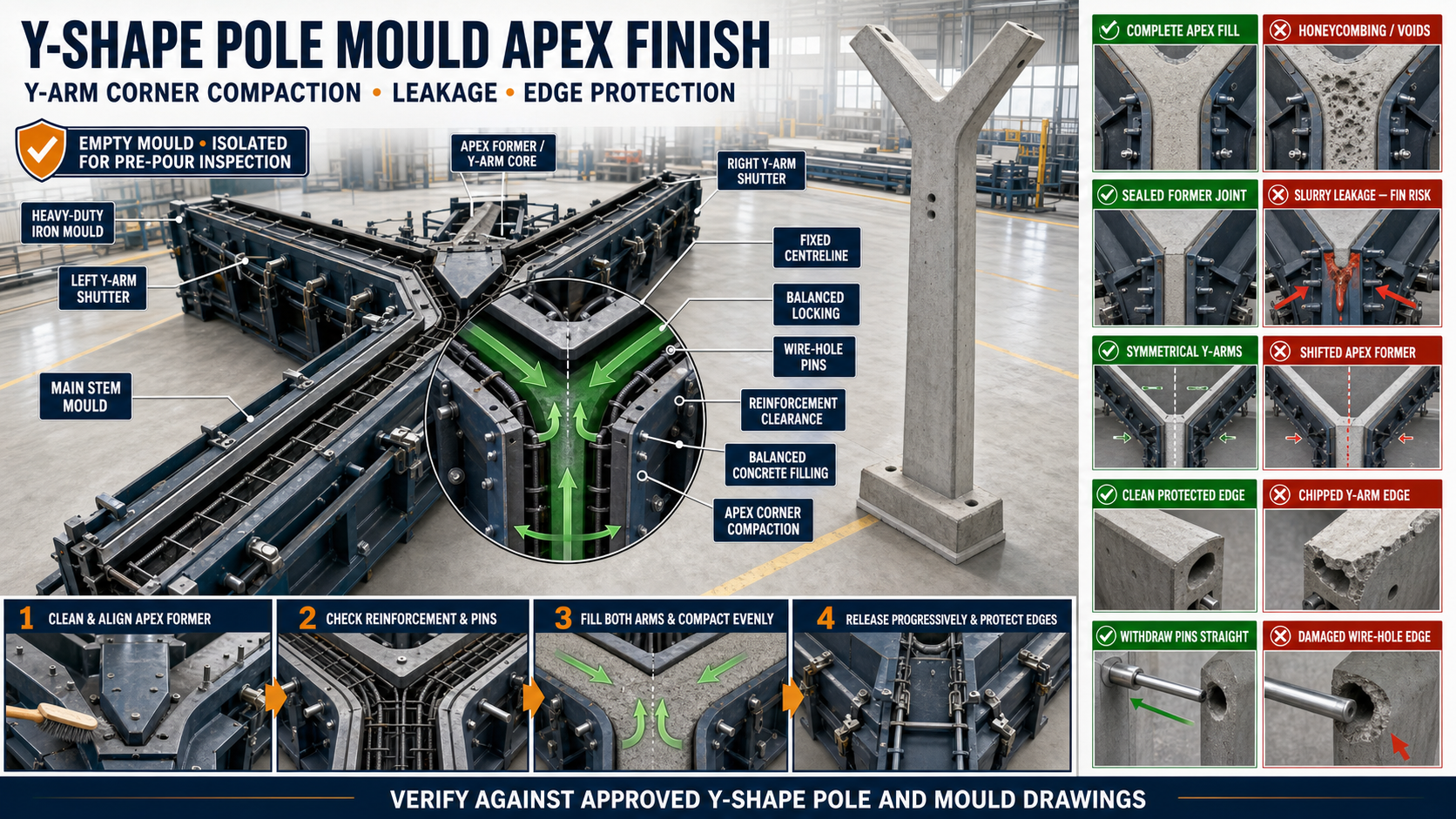
Y-Shape Pole Mould Apex Finish: Y-Arm Corner Compaction, Leakage and Edge Protection
Y-Shape Pole Mould Apex Finish: Y-Arm Corner Compaction, Leakage and Edge Protection
A precast Y-shape pole is commonly used for security fencing around industrial facilities, utility sites, farms, warehouses and other controlled boundaries.
The upper portion of the pole divides into two arms, creating a Y-shaped profile. The point where the main stem divides is the apex or Y-junction.
This area contains narrow concrete spaces, changes in direction and reinforcement intersections. It therefore requires accurate mould alignment, controlled concrete placement and effective compaction.
Poor preparation can produce honeycombing, slurry leakage, concrete fins, incomplete corners and damaged Y-arm edges.
What Is the Y-Shape Pole Apex?
The apex is the central junction where the vertical pole stem divides into two inclined Y-arms.
The mould must form:
• Main stem • Left Y-arm • Right Y-arm • Central apex • Internal Y-junction corners • Outer arm edges • Arm tips • Wire-hole or fixing-pin locations where specified
All geometry should follow the approved pole drawing.
Why the Apex Is Difficult to Cast
The apex can be difficult because:
• Concrete changes direction • Reinforcement may be congested • Space around bars may be limited • Aggregate can bridge across narrow sections • Air can become trapped • Vibration may not reach every corner • Multiple shutters meet in one region • Release-agent access may be difficult • Concrete edges may be fragile during demoulding
The concrete mix and mould arrangement should be designed for the required product.
What Is Apex Finish?
Apex finish describes the visual and dimensional quality of the concrete around the Y-junction and arm corners.
A satisfactory finish may require:
• Complete concrete filling • Smooth formed surfaces • Defined Y-profile • Continuous corners • Minimal fins • No significant voids • No broken edges • Correct arm alignment • Clean wire-hole positions • Compliance with the approved drawing
Surface appearance alone does not establish structural acceptance.
Heavy-Duty Iron Y-Shape Pole Mould
A Y-shape pole mould may include:
• Long stem mould • Left Y-arm shutter • Right Y-arm shutter • Y-arm core or junction former • End shutters • Apex profile inserts • Structural stiffeners • Hinges • Locating pins • Wire-hole pins • Quick locks • Chamfer strips • Base frame • Mechanical or hydraulic opening system
Every component should maintain the Y-profile during casting and vibration.
Common Apex and Y-Arm Defects
Possible defects include:
• Honeycombing • Surface voids • Incomplete apex • Missing corner • Concrete fin • Slurry-leakage marks • Chipped arm edge • Cracked arm tip • Unequal Y-arm profiles • Misaligned wire holes • Rough shutter-joint line • Reinforcement exposure • Air pockets
Recurring defects should be recorded according to their mould location.
What Causes Poor Apex Finish?
Common causes include:
• Inadequate concrete flow • Aggregate bridging • Congested reinforcement • Incorrect cage position • Insufficient compaction • Excessive vibration • Poor mould sealing • Loose apex former • Dirty contact surfaces • Worn locks • Damaged chamfer strips • Early demoulding • Poor release-agent coverage • Incorrect shutter-opening sequence
Several causes may act together.
Y-Arm Corner Compaction
Compaction removes trapped air and helps concrete fill the narrow spaces around the Y-junction.
Effective compaction should:
• Reach both Y-arms • Fill internal corners • Surround reinforcement • Avoid segregation • Maintain mould alignment • Prevent insert movement • Avoid over-vibration • Produce consistent surfaces
The compaction method should match the approved concrete mix and mould design.
Preparing the Mould
Before casting:
• Clean the complete mould • Open all accessible shutters • Remove hardened concrete • Clean the apex former • Clean Y-arm corners • Inspect wire-hole pins • Check chamfer strips • Inspect locating pins • Check hinges and locks • Verify mould alignment • Confirm the base frame is stable • Review the approved pole drawing
Concrete deposits in a narrow corner can change the Y-arm profile.
Inspecting the Apex Former
The apex former or Y-arm core controls the central junction.
Inspect for:
• Correct identification • Profile accuracy • Centreline alignment • Bending • Surface damage • Concrete buildup • Loose mounting • Cracked welds • Worn locating points • Demoulding taper • Contact with adjoining shutters
A damaged former can produce repeated apex defects.
Checking Y-Arm Symmetry
The two arms should follow the approved geometry.
Check:
• Left-arm position • Right-arm position • Apex centreline • Arm angle according to the drawing • Arm length • Arm-tip position • Corresponding profile dimensions • Wire-hole clearance • Shutter contact • Diagonal relationship
Do not assume both arms are correct because the mould closes.
Establishing a Fixed Centreline
Use a verified mould centreline to position the apex former and Y-arm shutters.
The centreline may be marked on:
• Base frame • Main stem mould • Apex former • End shutter • Y-arm support frame • Inspection jig
Both Y-arms should be checked relative to the same datum.
Checking Apex Shutter Joints
Several mould components may meet around the apex.
Inspect joints between:
• Main stem and Y-arm shutters • Left and right Y-arm sections • Apex former and outer shutter • Chamfer strips • End-forming components • Wire-hole pin supports
These intersections are common leakage paths.
Cleaning Contact Faces
Remove:
• Hardened slurry • Concrete particles • Rust flakes • Release-agent buildup • Damaged sealing material • Welding debris • Foreign objects
A thin deposit can create a gap large enough for cement slurry to escape.
Inspecting Joint Contact
Close the mould lightly and check:
• Continuous contact • Joint alignment • Steps between forming surfaces • Gaps between locks • Corner closure • Seal compression • Locating-pin engagement • Apex-former seating
Fully tightening one lock should not be used to force an obstructed joint closed.
Slurry Leakage Around the Apex
Cement slurry may escape through small gaps during casting and vibration.
Leakage can cause:
• Concrete fins • Rough joint marks • Honeycombing • Weak corner appearance • Loss of fine material • Difficult demoulding • Hardened buildup in the mould
The leak source should be corrected before the next casting cycle.
Common Leakage Locations
Inspect:
• Apex-former perimeter • Y-arm shutter intersections • Main-stem transition • Arm-tip end shutters • Wire-hole pin openings • Chamfer-strip joints • Hinge-side contact faces • Locking locations
Record each repeated leak location.
Joint-Sealing Methods
Depending on the mould design, sealing may use:
• Accurate steel-to-steel contact • Approved sealing strip • Mould gasket • Profile-specific seal • Approved compressible sealing component
The seal must not change the Y-pole geometry.
Installing Seals
A general procedure may include:
• Clean the sealing groove • Inspect mating surfaces • Select the approved seal • Install without stretching • Maintain continuity around corners • Avoid excessive overlap • Close the shutter lightly • Check uniform compression • Recheck after locking
Damaged, hardened or flattened seals should be replaced.
Inspecting Locks and Clamps
The apex area should be locked evenly.
Inspect:
• Wedge surfaces • Screw threads • Clamp pivots • Lock pins • Mounting brackets • Welds • Engagement • Concrete buildup • Wear • Alignment
Unequal locking can distort the Y-arm profile.
Balanced Locking Sequence
A general sequence may include:
1. Seat the Apex Former
Engage the fixed locating points.
2. Position Both Y-Arm Shutters
Close them evenly.
3. Engage Primary Locators
Confirm the centreline.
4. Apply Locks Lightly
Start all locks.
5. Check Apex Joints
Inspect contact around the complete junction.
6. Tighten Progressively
Use a balanced left-and-right sequence.
7. Recheck Arm Symmetry
Ensure locks did not move the profile.
8. Inspect Sealing
Confirm all gaps are controlled.
Follow the mould manufacturer’s approved sequence.
Wire-Hole Pin Clearance
Y-shape poles may contain wire-hole pins for security fencing.
Check that:
• Pins follow the approved spacing • Pins remain straight • Pin ends are supported • Reinforcement does not obstruct them • Pins do not push the Y-arm former • Release agent is applied uniformly • Pin withdrawal path remains clear • Pin openings are sealed against slurry
Do not force a pin through misaligned supports.
Reinforcement Placement at the Apex
The reinforcement cage should match the Y-shaped profile.
Check:
• Main-stem reinforcement • Left-arm reinforcement • Right-arm reinforcement • Apex bar transition • Required concrete cover • Bar spacing • Cage supports • Tie-wire position • Wire-hole pin clearance • Arm-tip reinforcement • Stability during shutter closure
Reinforcement should not push against the apex former.
Concrete Cover at Y-Arm Corners
Concrete cover may become difficult to maintain around narrow corners.
Verify cover at:
• Outer Y-arm faces • Inner Y-junction • Arm tips • Main stem transition • Wire-hole locations • Chamfered edges
Requirements should follow the approved structural drawing.
Applying Mould Release Agent
Apply a suitable release agent after cleaning and inspection.
The application should be:
• Thin • Uniform • Present across the apex former • Applied inside Y-arm corners • Present on chamfer strips • Applied to wire-hole pins • Free from excessive pooling • Kept away from reinforcement
Excess release agent can collect in the apex and affect the concrete surface.
Concrete Mix Considerations
The concrete should follow the approved mix design.
Important properties may include:
• Workability • Cohesion • Aggregate grading • Maximum aggregate size • Resistance to segregation • Compatibility with vibration • Required strength • Surface-finish performance
Do not add uncontrolled water at the mould to improve flow.
Aggregate Bridging
Aggregate bridging occurs when coarse particles block a narrow section and prevent mortar from filling the space.
It may occur at:
• Inner apex corner • Narrow Y-arm sections • Around congested bars • Near wire-hole pins • Arm tips • Chamfer transitions
The approved concrete mix and placement method should reduce this risk.
Concrete Placement Sequence
A controlled placement sequence may include:
1. Fill the Main Stem Progressively
Avoid overloading one area.
2. Approach the Apex Gradually
Allow concrete to flow around reinforcement.
3. Place Concrete Into Both Y-Arms Evenly
Maintain similar levels.
4. Fill Narrow Corners Carefully
Prevent aggregate bridging.
5. Monitor Pins and Formers
Check for movement.
6. Complete the Arm Tips
Avoid trapping air.
7. Inspect the Mould Externally
Look for leakage or joint movement.
The exact sequence should match the mould orientation and plant procedure.
Do Not Fill One Arm Completely First
Unbalanced concrete placement can:
• Push the apex former sideways • Move reinforcement • Open one shutter joint • Create different compaction • Distort the Y-arm profile • Increase slurry leakage
Fill both arms in a balanced manner.
Compaction Methods
Depending on the mould system, compaction may use:
• Shutter vibrators • Vibrator table • Approved internal vibrator • Controlled external vibration • A suitable combined method
The method should reach the apex without damaging the mould or reinforcement.
Using an Internal Vibrator Near the Apex
Where approved:
• Use suitable equipment • Avoid contact with reinforcement • Avoid striking shutters • Keep clear of wire-hole pins • Use controlled insertion • Avoid excessive duration • Follow the approved sequence
The vibrator should not be used to force aggregate through an unsuitable gap.
Using Shutter Vibrators
Shutter vibrators transfer energy into the mould plates.
Check:
• Mounting-pad condition • Bolt security • Approved vibrator position • Mould stiffness • Rotation and operation • Nearby lock security • Apex-former stability
Incorrect mounting can produce uneven compaction.
Warning Signs During Casting
Watch safely for:
• Slurry leakage • Lock movement • Y-arm shutter vibration • Apex-former movement • Wire-hole pin displacement • Uneven concrete level • Unusual metallic noise • Local shutter bulging
Stop the process safely if significant movement occurs.
Avoiding Under-Compaction
Under-compaction may produce:
• Honeycombing • Surface voids • Incomplete corners • Exposed reinforcement • Rough apex • Weak-looking arm tips • Poor wire-hole edges
The solution should follow the approved mix and compaction procedure.
Avoiding Over-Compaction
Excessive vibration can cause:
• Segregation • Slurry leakage • Mould-joint opening • Insert movement • Reinforcement movement • Accumulation of paste • Uneven finish
More vibration is not always better.
Preparing for Demoulding
Before opening the mould:
• Confirm adequate concrete strength • Support the Y-shape pole • Isolate powered equipment • Release hydraulic pressure • Mechanically support shutters • Clean concrete around locks • Remove wire-hole pins in the approved sequence • Identify the correct shutter-opening order • Keep personnel clear of pinch points • Prepare suitable handling equipment
Y-arm edges can be fragile during early demoulding.
Wire-Hole Pin Removal
Where pins pass through the Y-arms:
• Clean exposed pin ends • Release all retainers • Support the pole • Pull each pin straight • Avoid sideways force • Protect hole edges • Clean pins immediately • Inspect the formed holes
A stuck pin should not be removed using uncontrolled hammering.
Correct Y-Arm Demoulding Sequence
A general procedure may include:
1. Support the Pole
Prevent movement or rotation.
2. Remove Approved Pins and Inserts
Follow the specified order.
3. Release Secondary Locks
Open them progressively.
4. Support Y-Arm Shutters
Prevent sudden movement.
5. Release Primary Locks
Keep personnel clear.
6. Separate the Apex Former Carefully
Create controlled clearance.
7. Open Both Arm Shutters Evenly
Avoid dragging across concrete edges.
8. Release the Main Stem Shutters
Follow the mould sequence.
9. Move the Pole Safely
Use approved handling arrangements.
Do not pull one Y-arm shutter against a locked opposite side.
Edge Protection During Demoulding
Protect:
• Apex corner • Inner Y-junction • Outer Y-arm edges • Arm tips • Wire-hole edges • Stem-to-arm transitions
Avoid:
• Sudden impact • Direct prying on concrete • Dragging steel shutters • Unsupported lifting • Incorrect pull direction • Premature demoulding
Chamfer strips may reduce sharp-edge damage when included in the approved design.
What Causes Y-Arm Edge Breakage?
Common causes include:
• Insufficient concrete strength • Poor release-agent coverage • Concrete fins locking joints • Incorrect shutter sequence • Apex former pulled sideways • Shutter distortion • Unsupported pole • Reinforcement movement • Honeycombing near the edge • Damaged chamfer strip
Repeated breakage should be traced to the exact mould location.
Post-Demoulding Apex Inspection
Inspect the finished pole for:
• Apex completeness • Left-arm profile • Right-arm profile • Arm symmetry • Inner corners • Outer edges • Arm tips • Wire holes • Concrete fins • Honeycombing • Cracks • Chipped edges • Reinforcement exposure • Surface finish
Record defects according to mould side and location.
Checking Y-Arm Alignment
Use approved measurements or templates to inspect:
• Apex centreline • Arm-tip positions • Left and right profiles • Arm-angle relationship • Symmetry • Wire-hole alignment • Pole-stem centreline • Cross-section dimensions
No generic Y-arm angle or size should be assumed.
Troubleshooting Common Problems
Problem: Honeycombing at the Apex
Possible causes:
• Inadequate compaction • Aggregate bridging • Congested reinforcement • Concrete placement was unbalanced • Slurry leakage removed fine material • Concrete workability was unsuitable
Problem: One Y-Arm Is Incomplete
Possible causes:
• Air was trapped • Concrete level was uneven • Aggregate blocked the arm • Compaction did not reach the corner • Reinforcement obstructed the cavity
Problem: Concrete Fin Around the Y-Junction
Possible causes:
• Apex-former joint gap • Dirty contact surface • Damaged seal • Uneven locks • Misaligned former
Problem: Y-Arm Edge Breaks During Demoulding
Possible causes:
• Concrete strength was insufficient • Shutter was pulled sideways • Release agent was missing • Concrete fin locked the edge • Arm was unsupported • Shutter sequence was incorrect
Problem: Left and Right Arms Are Unequal
Possible causes:
• Apex former shifted • Y-arm shutters are misaligned • Locks were tightened unevenly • Reinforcement pushed one shutter • Concrete pressure was unbalanced
Problem: Wire Holes Are Damaged
Possible causes:
• Pins were pulled at an angle • Concrete was too weak • Pins were dirty • Release agent was missing • Pin supports were misaligned
Problem: Surface Contains Large Air Voids
Possible causes:
• Poor concrete placement • Inadequate vibration • Aggregate bridging • Release agent pooled in the corner • Mould geometry trapped air
Correcting Repeated Apex Defects
A corrective process may include:
• Mapping the defect location • Cleaning the apex mould components • Checking former alignment • Inspecting seals • Repairing locks and hinges • Verifying reinforcement clearance • Reviewing placement sequence • Reviewing vibration method • Checking concrete consistency • Inspecting demoulding timing • Conducting a controlled trial casting
Do not rely only on patching finished poles.
Apex-Former Maintenance Checklist
After every casting cycle:
• Clean the apex former • Remove slurry from joints • Inspect forming surfaces • Check profile accuracy • Inspect locating pins • Check locks • Examine welds • Inspect chamfer strips • Check wire-hole pin guides • Verify shutter movement • Apply corrosion protection during storage • Record recurring defects
Do not use cleaning tools that dent the forming surface.
Pre-Pour Apex Checklist
Before concrete placement, confirm:
• Correct Y-arm components are installed • Apex former is centred • Both Y-arm shutters are aligned • Arm symmetry is checked • Contact faces are clean • Seals are continuous • Locating pins are seated • Locks are progressively tightened • Wire-hole pins are aligned • Reinforcement follows the drawing • Concrete cover is verified • Release agent is uniformly applied • Shutter vibrators are securely mounted where used • No tools remain inside the mould
Benefits of Correct Apex Production
Correct mould setup and casting provide:
• Complete Y-junction filling • Cleaner Y-arm corners • Reduced honeycombing • Lower slurry leakage • Fewer concrete fins • Better arm symmetry • Cleaner wire holes • Reduced edge damage • Easier demoulding • More consistent security-pole production
Conclusion
The apex and Y-arm corners are critical areas in a precast Y-shape pole. Their finish depends on accurate iron mould alignment, clean and sealed shutter joints, suitable reinforcement clearance and balanced concrete placement.
Compaction should reach both arms and the central junction without causing segregation, insert movement or excessive leakage. During demoulding, the Y-arm shutters and apex former should be released progressively to protect the fresh concrete edges.
A properly maintained heavy-duty iron Y-shape pole mould helps manufacturers produce complete apex profiles, symmetrical arms and clean edges for security-fencing projects.