
Precast Infrastructure Moulds
Y Shape Concrete Pole Mould for Security Fencing: Complete Manufacturing Guide
Explore Y shape concrete pole mould sizes, security-fencing applications and the complete RCC Y-post manufacturing process from casting to demoulding.
By Paras Steel Industries ·
Y Shape Concrete Pole Mould for Security Fencing: Complete Manufacturing Guide
Y Shape Concrete Pole Mould for Security Fencing: Complete Manufacturing Guide
Security fencing around industrial facilities, solar parks, railway lines and utility compounds requires strong and durable supporting posts.
Y-shape concrete poles combine a reinforced vertical post with two outward-facing arms at the top. The arms can support barbed wire, razor wire or another approved fencing arrangement.
A Y shape concrete pole mould helps precast manufacturers produce these specialised posts with consistent dimensions, properly formed arms and accurately positioned wire holes.
Because the Y-head section has a more complex profile than a straight concrete pole, mould strength and fabrication accuracy are especially important.
This guide explains Y-pole sizes, mould features, applications and the complete manufacturing process.
What Is a Y Shape Concrete Pole?
A Y shape concrete pole is an RCC fencing post with a straight lower body and a flared Y-shaped upper section.
The main pole provides vertical support, while the two upper arms extend outward to support additional security wire.
Depending on the fencing design, the arms may carry:
Barbed wire
Concertina coil
Razor wire
Chain-link extension
Project-specific security wire
The pole can include holes through the main body and Y-arms. These holes allow fencing wire to pass through or be fixed at planned intervals.
What Is a Y Shape Pole Mould?
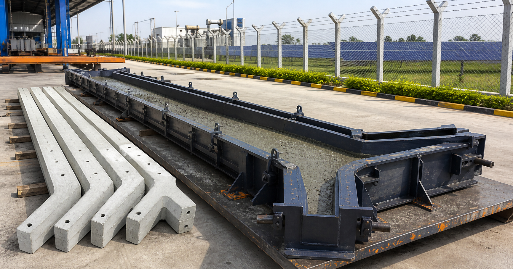
A Y shape pole mould is a heavy-duty iron form used to manufacture precast concrete Y-posts.
The mould creates the long pole body, Y-shaped head, tapered profile and required wire holes.
It generally consists of:
Long flat casting channel
Heavy-duty iron plates
Flared Y-head core
Outer stiffener ribs
Gusset support plates
Removable wire-hole pins
Side locking system
Tapered demoulding profile
Lifting and handling provisions
The complete mould is placed horizontally during reinforcement installation, concrete pouring and vibration.
Benefits of Y Shape Concrete Poles
Improved Security-Fencing Support
The outward-facing Y-arms create additional fixing positions above the main fence line.
Durable Concrete Construction
Properly manufactured RCC poles can withstand outdoor weather, moisture and regular fencing loads.
Termite and Rot Resistance
Concrete poles do not suffer from termite attack or timber decay.
Consistent Wire Alignment
Built-in mould pins can create repeatable holes at the required spacing.
Suitable for Different Sites
Y-posts can be used for agricultural, industrial, transport and high-security perimeter fencing.
Reduced On-Site Drilling
Wire holes formed during casting eliminate or reduce the need to drill cured concrete poles.
Repeat Production
A precision-made iron mould helps manufacturers produce consistent poles across repeated casting cycles.
Standard Agriculture and Farm Y-Pole Sizes
Common agricultural Y-pole heights may include:
7 feet or approximately 2100 mm
8 feet or approximately 2400 mm
A commonly required base cross-section may be:
100 x 100 mm
The Y-arm spread may range from approximately:
300 to 400 mm
These dimensions can be adjusted according to fence height, installation depth and wire arrangement.
Industrial and Security Y-Pole Sizes
Heavy-duty security poles may be produced in heights such as:
8 feet or approximately 2400 mm
9 feet or approximately 2700 mm
10 feet or approximately 3000 mm
Heavy-duty base configurations may include:
125 x 125 mm straight base
Tapered profile from approximately 150 mm to 100 mm
The Y-arm spread may range from approximately:
400 to 500 mm
The final pole dimensions must follow the approved fencing and reinforcement design.
Straight and Tapered Pole Profiles
Straight Pole Body
A straight pole maintains approximately the same cross-section throughout most of its vertical length.
It provides a uniform appearance and relatively simple reinforcement arrangement.
Tapered Pole Body
A tapered pole has a wider lower section and gradually reduces toward the top.
The wider base supports the portion exposed to higher bending forces, while the reduced upper profile can control concrete weight.
The taper must be accurately incorporated into the mould to maintain consistency.
Importance of the Y-Head Core
The Y-head core forms the two upper arms of the concrete pole.
This section must maintain:
Correct arm angle
Uniform arm thickness
Required spread
Smooth internal corners
Adequate reinforcement cover
Accurate wire-hole positions
A poorly supported Y-head mould can spread or deform under concrete pressure.
Heavy gusset plates and stiffener ribs help maintain the arm geometry during pouring and vibration.
Important Mould Specifications
Heavy-Duty Iron Construction
Paras Steel Industries manufactures Y shape pole moulds using heavy-duty iron.
Depending on the pole size and production requirements, the mould may use approximately:
4 mm iron plate
5 mm iron plate
6 mm iron plate
The appropriate thickness depends on mould length, concrete pressure, vibration method and support-frame design.
Reinforced Gusset Supports
The Y-head section requires additional support to prevent bending or spreading.
External gusset plates and stiffeners reinforce the complex upper profile.
Flared Y-Top Core
The specialised core creates two outward-facing concrete arms.
Its angle and dimensions can be customised according to the required fencing system.
Built-In Wire-Hole Pins
Removable rods or core pins form aligned holes while the concrete is cast.
The hole diameter and spacing can be customised according to the fencing layout.
Tapered Demoulding Profile
Calculated draft angles help release the pole without damaging the arm joints and edges.
Flat Casting Arrangement
The mould operates on a horizontal casting bed, supporting controlled reinforcement positioning and concrete filling.
Vibration Compatibility
The mould can be used with a suitable:
Vibrator table
Shutter vibrator
Surface vibrator
Approved hand-compaction method for suitable small production
The selected compaction method should produce dense concrete without moving the reinforcement or wire-hole pins.
Wire-Hole Configuration
The hole layout should be confirmed before mould manufacturing.
Important details include:
Number of holes
Hole diameter
Distance between holes
Position of the first hole
Position of the final hole
Holes in the main post
Holes in each Y-arm
Straight or angled hole direction
Wire or fastening type
A complete pole drawing should show all measurements clearly.
Applications of Y Shape Concrete Poles
Solar Power Plants
Y-posts can support security fencing around solar panels, electrical equipment and large solar parks.
Electrical Substations
Utility sites require controlled perimeter access and durable outdoor fencing.
Wind-Energy Projects
Concrete Y-poles can be used around turbines, control equipment and power infrastructure.
Factories and Warehouses
Industrial facilities use Y-shape posts for perimeter and restricted-area fencing.
Railway Boundaries
Concrete posts can support security fencing along railway land and operational areas.
Highway Rights of Way
Y-poles may be used along controlled highway boundaries according to project specifications.
Agricultural Farms
Farmers can use Y-posts for crop protection, livestock enclosures and property boundaries.
Military and Restricted Compounds
Project-specific Y-poles can support approved high-security fencing systems.
Water-Treatment and Utility Sites
The poles can protect reservoirs, treatment facilities, pumping stations and utility compounds.
Complete Manufacturing Process
Step 1: Finalise the Pole Drawing
Confirm:
Total pole height
Installation depth
Base cross-section
Top cross-section
Straight or tapered body
Y-arm angle
Y-arm spread
Hole diameter and spacing
Reinforcement arrangement
Concrete grade
Do not begin mould or pole production using only an approximate market size.
Step 2: Prepare the Mould
Clean the complete mould channel, Y-head core and wire-hole pins.
Remove hardened concrete and inspect the iron surfaces for bending or damage.
Step 3: Apply Release Agent
Apply a suitable concrete release agent evenly to all concrete-contact surfaces.
Ensure coverage inside the Y-arm sections and around the pin locations.
Step 4: Prepare the Reinforcement
Cut and assemble the reinforcement according to the approved RCC pole design.
The reinforcement should extend correctly into both Y-arms.
Special attention is required at the arm junction because this is a geometrically sensitive section.
Step 5: Position the Reinforcement
Place the reinforcement inside the mould using suitable cover spacers.
Confirm that the bars do not touch the iron surface.
Step 6: Install the Wire-Hole Pins
Position the removable pins according to the approved spacing.
Secure them so they do not shift during concrete pouring and vibration.
Step 7: Close and Lock the Mould
Close all shutters and tighten the locking arrangement evenly.
Check the alignment of the main pole body and Y-head core.
Step 8: Prepare the Concrete Mix
Measure cement, aggregates, sand, water and approved admixtures accurately.
Use a suitable concrete mixer to prepare a uniform batch.
The concrete should have adequate workability to fill the Y-arm sections without using excessive water.
Step 9: Pour the Concrete
Place concrete gradually from the lower pole body toward the Y-head section.
Avoid filling one arm completely before the other. Balanced placement helps control pressure and reinforcement movement.
Step 10: Compact the Concrete
Apply controlled vibration to remove trapped air.
Pay special attention to:
Y-arm tips
Arm junction
Wire-hole pins
Reinforcement congestion
Tapered sections
Insufficient compaction can create honeycombing, while excessive vibration can cause segregation.
Step 11: Finish the Exposed Surface
Level and smooth the exposed side of the pole.
Remove excess concrete from the mould edges and pin positions.
Step 12: Allow Initial Setting
Allow the concrete to gain sufficient strength before removing pins or opening the mould.
The timing depends on the concrete mix, curing conditions and production process.
Step 13: Remove the Hole Pins
Release and remove the pins carefully.
Do not apply force that could crack the surrounding concrete.
Step 14: Demould the Pole
Open the mould and release the Y-pole using the designed lifting method.
Support the pole along its length to avoid bending stress during handling.
Step 15: Cure the Pole
Continue curing according to the approved procedure.
Proper curing improves strength, durability and crack resistance.
Step 16: Inspect the Finished Pole
Check every pole for:
Correct total length
Straight alignment
Correct Y-arm angle
Uniform arm spread
Accurate cross-section
Clean wire holes
Surface honeycombing
Cracks around the Y-junction
Chipped arm tips
Reinforcement exposure
Step 17: Store Safely
Store poles on a level platform using supports at suitable intervals.
Avoid unsupported stacking that could cause bending or breakage.
Production Capacity Planning
Daily Y-pole output depends on:
Number of mould cavities
Number of mould sets
Concrete-mixing capacity
Reinforcement preparation
Filling and vibration time
Initial setting period
Demoulding schedule
Curing space
Labour availability
Handling equipment
Storage capacity
A manufacturer should match mould quantity to realistic factory capacity rather than buying moulds based only on a target number.
Machinery and Equipment Required
A Y-shape pole production setup may include:
Heavy-duty iron Y-pole mould
Concrete mixer machine
Vibrator table or suitable vibrator
Reinforcement cutting machine
Reinforcement bending equipment
Material weighing system
Concrete transportation trolley
Lifting equipment
Curing facility
Panel or pole shifting trolley
Storage supports
Common Casting Defects
Incomplete Y-Arms
This may occur because of poor concrete flow or insufficient vibration in the upper section.
Cracks at the Arm Junction
Possible causes include early demoulding, incorrect handling, poor reinforcement position or inadequate curing.
Misaligned Wire Holes
Pins may move if they are not secured properly before pouring.
Honeycombing
Insufficient compaction or unsuitable concrete workability can leave voids around reinforcement and pins.
Bent or Twisted Poles
This can result from mould misalignment, uneven support, early handling or improper storage.
Chipped Arm Tips
Y-arm ends can be damaged during demoulding or transportation if they are not supported correctly.
Mould Maintenance Tips
Clean the mould after every casting cycle.
Remove concrete from the Y-head core and pin holes.
Apply release agent evenly before pouring.
Inspect the 4 mm, 5 mm or 6 mm iron plates for bending.
Check gussets and stiffeners for damage.
Inspect all pins for straightness and wear.
Lubricate moving locks without contaminating contact surfaces.
Protect exposed iron surfaces from moisture and rust.
Store the mould on a flat and adequately supported bed.
Factors Affecting Mould Price
Pole Height
A 10-foot mould requires more material and support than a 7-foot mould.
Base Cross-Section
Heavy 125 x 125 mm or tapered profiles increase mould dimensions.
Iron Plate Thickness
The selected plate thickness affects mould weight, durability and cost.
Y-Arm Spread
A wider and heavier Y-head requires additional fabrication and reinforcement.
Wire-Hole Pattern
The number, size and position of removable pins influence mould complexity.
Number of Cavities
Multi-cavity configurations require more material and production-floor space.
Custom Taper
A project-specific taper requires precision profile fabrication.
Handling System
Custom lifting handles, opening mechanisms and production arrangements affect the final quotation.
Frequently Asked Questions
Which material is used for the Y-pole mould?
Paras Steel Industries manufactures Y shape pole moulds using heavy-duty iron.
Which pole heights can be manufactured?
Common sizes include approximately 7, 8, 9 and 10 feet. Custom heights can also be discussed.
What is the standard base size?
Common base options include approximately 100 x 100 mm and 125 x 125 mm. Tapered configurations are also available.
Which iron plate thickness is used?
Depending on the mould design, approximately 4 mm, 5 mm or 6 mm heavy-duty iron plates can be used.
Can wire holes be formed during casting?
Yes. Removable core pins can create correctly positioned wire holes without drilling the cured pole.
Can the Y-arm spread be customised?
Yes. The arm angle and spread can be manufactured according to the customer’s approved drawing.
Which vibration system can be used?
The mould can support a suitable vibrator table, shutter vibrator or other approved compaction arrangement.
How can I request a quotation?
Share the pole drawing, total height, base size, Y-arm dimensions, hole pattern, mould quantity and delivery location with Paras Steel Industries.
Conclusion
A Y shape concrete pole mould helps precast manufacturers produce durable RCC posts for agricultural, industrial and security-fencing projects.
The correct mould should provide strong iron construction, a reinforced Y-head core, accurate wire-hole pins and a convenient demoulding profile.
Production quality also depends on reinforcement positioning, concrete mixing, controlled vibration, curing and careful handling.
Paras Steel Industries manufactures heavy-duty iron Y shape pole moulds in standard and custom dimensions.
Contact Paras Steel Industries with your Y-post drawing and production requirements to discuss a suitable mould configuration and quotation.