
Precast Machinery Guide
Vibrator Table Spring and Motor Synchronization: Uneven Vibration Troubleshooting Guide
Uneven vibration can cause poor concrete compaction, surface defects and inconsistent precast products. This guide explains how to inspect vibrator table springs, motor synchronization, mounting bolts, rotation direction and load distribution safely.
By Paras Steel Industries ·
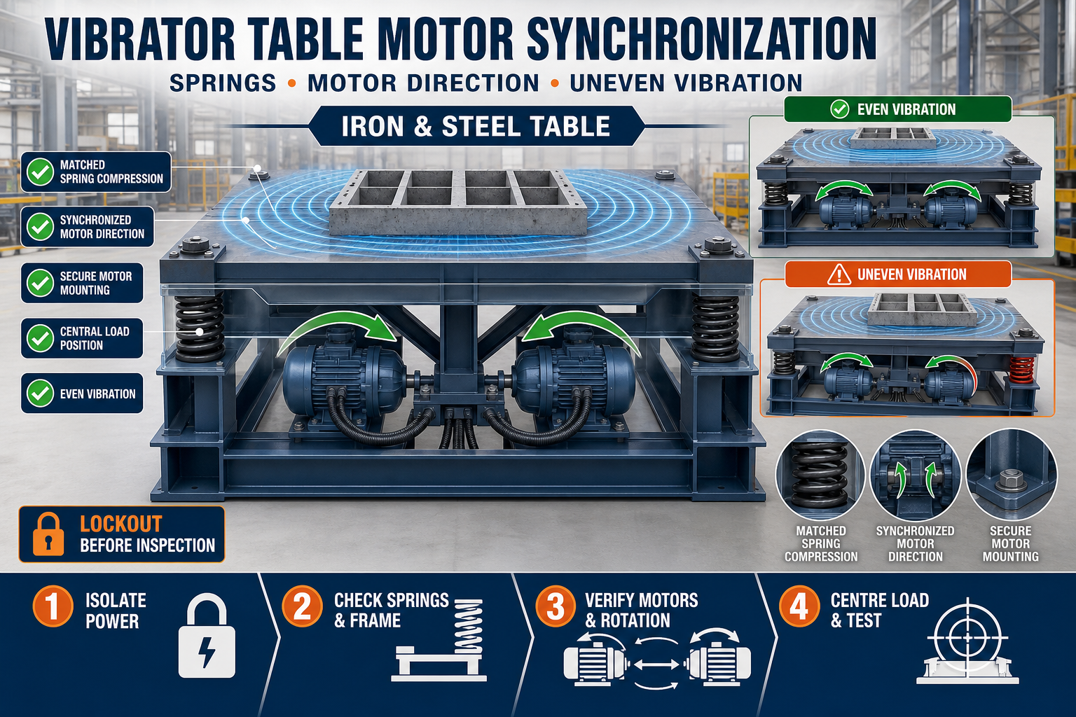
Vibrator Table Spring and Motor Synchronization: Uneven Vibration Troubleshooting Guide
Vibrator Table Spring and Motor Synchronization Guide
A vibrator table helps compact fresh concrete inside precast moulds by transferring controlled vibration through its working platform. When the table vibrates unevenly, one mould area may receive excessive vibration while another area receives insufficient compaction.
Uneven vibration can cause honeycombing, air pockets, segregation, inconsistent surface finish and unnecessary stress on the table structure. Common causes include damaged springs, incorrect motor synchronization, loose mounting bolts, uneven mould placement and structural distortion.
This guide explains how to identify and troubleshoot uneven vibration in a precast vibrator table.
What Is Vibrator Table Motor Synchronization?
Large vibrator tables may use more than one vibration motor. Motor synchronization means that the motors operate together to create the intended vibration pattern.
Correct synchronization depends on factors such as:
• Motor specification • Motor mounting position • Rotation direction • Electrical connection • Eccentric-weight setting • Mounting rigidity • Table-frame design • Spring condition • Load distribution
The required configuration should follow the vibrator table manufacturer’s drawing and the motor manufacturer’s instructions.
Why Is Even Vibration Important?
Uniform vibration helps concrete settle consistently throughout the mould. It removes trapped air and helps fresh concrete flow around reinforcement and into corners.
Balanced table vibration can support:
• Uniform concrete compaction • Reduced honeycombing • Consistent surface finish • Better filling of mould corners • Stable concrete quality • Reduced mould movement • Lower stress on table components • More consistent production cycles
Excessive vibration is not necessarily better. It may cause segregation, slurry leakage or movement of reinforcement and embedded components.
Common Signs of Uneven Vibration
Operators may notice uneven vibration through the following symptoms:
• One side of the table vibrates more strongly • Moulds move toward one side • Concrete compacts faster at one end • Air bubbles remain in specific areas • Unusual noise comes from the frame • The table moves excessively on the floor • Springs compress differently • Motor mounting bolts become loose • Cracks appear near welded joints • Surface finish varies across the product • Electrical current differs between similar motors
Stop the machine if the vibration becomes severe, produces abnormal noise or creates an unsafe condition.
Safety Before Troubleshooting
A vibrator table contains electrical, mechanical and stored-energy hazards. Inspection must only be performed after isolating the equipment.
Before troubleshooting:
1. Stop the vibrator table completely. 2. Disconnect and isolate the electrical supply. 3. Apply the plant’s lockout and tagout procedure. 4. Wait until all movement has stopped. 5. Remove the mould and concrete load where required. 6. Prevent accidental machine startup. 7. Use suitable personal protective equipment. 8. Allow qualified personnel to inspect electrical components.
Never touch motors, springs, eccentric weights or rotating components while the system is operating.
Check the Vibrator Table Base
The table foundation should be stable, level and suitable for the machine. An uneven or weak base can make the complete assembly move differently at each corner.
Inspect:
• Foundation level • Anchor-bolt condition • Base-frame contact • Cracks around anchoring points • Loose support plates • Unwanted contact with nearby structures • Accumulated concrete underneath the frame • Floor settlement
The machine should not touch walls, columns or other equipment unless the design specifically requires that connection.
Inspect All Springs
Springs isolate the vibrating platform from the stationary base. If one spring is broken, weak, incorrectly seated or different from the others, the platform may tilt and vibrate unevenly.
Check every spring for:
• Cracks or broken coils • Permanent compression • Corrosion • Incorrect seating • Unequal height • Sideways bending • Contact with surrounding parts • Loose spring retainers • Concrete buildup • Mismatched spring type
Springs used together should match the approved machine specification. Do not replace only one spring with an unrelated size or stiffness.
Checking Spring Compression
Place the table in its normal unloaded condition and compare the spring positions. Then check the machine under the approved operating load.
Unequal spring compression may indicate:
• Uneven load distribution • A weak or damaged spring • Distorted platform structure • Incorrect motor position • Misaligned spring seats • Concrete buildup on the platform • Unequal mould weight distribution
Spring compression should be evaluated according to the equipment manufacturer’s specification. Do not judge spring performance only by visual appearance.
Inspect Motor Mounting
Vibration motors must be firmly attached to the designed mounting plates. Loose bolts reduce vibration transfer and can damage the motor, mounting plate and table frame.
Check:
• Motor mounting bolts • Bolt-tightening condition • Locking arrangements • Mounting-plate flatness • Cracks near bolt holes • Welded motor brackets • Motor orientation • Electrical cable support • Protective covers
Fasteners should be tightened according to the motor manufacturer’s specified procedure. Do not use assumed torque values.
Confirm Motor Rotation Direction
In a multi-motor vibrator table, rotation direction plays an important role in producing the intended vibration pattern. Incorrect wiring or phase sequence can make motors work against each other or create unwanted lateral movement.
A qualified electrician should verify:
• Rotation direction of each motor • Phase sequence • Electrical connection • Motor terminal arrangement • Control-panel configuration • Current balance • Protective-device condition
The required direction depends on the table design. Do not reverse a motor without checking the approved electrical and mechanical drawing.
Check Eccentric-Weight Settings
Vibration motors generate force through rotating eccentric weights. If the weights are set differently, the motors may produce unequal vibration.
After isolating the electrical supply, inspect:
• Weight position on each motor • Matching adjustment settings • Tightness of weight fasteners • Condition of protective covers • Signs of movement or slipping • Correct orientation
Both motors should be configured according to the machine design and motor instructions. Increasing the weight setting without approval can overload the table, springs and moulds.
Motor Synchronization Problems
Motors may fail to operate together because of:
• Incorrect motor selection • Different eccentric-weight settings • Opposite or incorrect rotation • Loose motor mounting • Electrical voltage imbalance • Damaged bearings • Unequal supply conditions • Incorrect control wiring • Structural cracks • Excessive or uneven load
Motor synchronization should be checked after confirming the mechanical condition of the table.
Inspect Electrical Current
Similar motors operating under similar conditions should be evaluated for abnormal differences in electrical current. A significant difference may indicate mechanical resistance, wiring problems or motor damage.
Electrical testing must be carried out by qualified personnel using suitable instruments.
Check:
• Supply voltage • Current on each motor • Phase balance • Motor insulation condition • Terminal tightness • Overload protection • Cable condition • Control-panel connections
Do not continue operating a motor that overheats, trips repeatedly or produces unusual noise.
Check Table-Top Alignment
The vibrating platform should remain structurally straight and properly supported. A bent or cracked table top can transfer vibration unevenly.
Inspect:
• Platform level • Main structural members • Cross members • Welded joints • Motor mounting plates • Spring-seat positions • Local deformation • Concrete buildup • Contact between moving and stationary frames
Cracked welds and distorted members should be assessed and repaired by qualified personnel.
Check Mould Placement
Even when the vibrator table is functioning correctly, poor mould placement can create uneven vibration.
Before starting the machine:
• Position the mould according to the approved loading area • Keep its centre of gravity properly located • Avoid placing all weight on one side • Use the specified clamping arrangement • Confirm that the mould base sits evenly • Remove concrete deposits between the mould and table • Do not exceed the approved table load • Distribute multiple moulds evenly
An off-centre mould can overload specific springs and change the table’s movement.
Inspect Mould Clamping
The mould must remain securely positioned during vibration. Loose or uneven clamping can create noise, movement and inconsistent vibration transfer.
Check:
• Clamp position • Clamp condition • Contact surfaces • Tightening sequence • Mould-base flatness • Stopper alignment • Locking pins • Worn clamp components
Do not use temporary or unsafe clamping arrangements.
Troubleshooting Uneven Vibration Step by Step
Use the following practical sequence:
1. Stop and electrically isolate the vibrator table. 2. Remove the mould and clean the platform. 3. Inspect the foundation and anchor points. 4. Check the table frame for cracks or distortion. 5. Compare all springs and spring seats. 6. Inspect motor mounting bolts and brackets. 7. Confirm matching eccentric-weight settings. 8. Ask a qualified electrician to check rotation and phase sequence. 9. Test the table without a mould according to the approved procedure. 10. Place the mould centrally and secure it. 11. Conduct a controlled loaded test. 12. Observe movement, noise and compaction behaviour. 13. Record the findings and corrective action.
Change only one major setting at a time. This makes it easier to identify the actual cause of the problem.
Common Problems and Possible Causes
One Side Vibrates More Strongly
Possible causes include a damaged spring, unequal eccentric-weight settings, loose motor mounting or off-centre mould placement.
Table Moves Sideways
Check motor rotation, spring alignment, foundation level, anchor points and load position.
Mould Travels Across the Platform
The mould may be poorly clamped, positioned away from the designed loading area or subjected to excessive lateral vibration.
Excessive Noise
Inspect loose bolts, worn bearings, cracked welds, metal-to-metal contact and unsecured mould components.
Poor Compaction at One End
Check motor operation, table-frame stiffness, spring condition, mould seating and concrete placement sequence.
Motor Overheating
Possible causes include electrical imbalance, damaged bearings, loose mounting, excessive eccentric force or operation outside the approved duty cycle.
Repeated Bolt Loosening
Check mounting-plate flatness, fastener condition, locking method, structural vibration and the approved tightening procedure.
Preventive Maintenance Checklist
Daily Checks
• Clean concrete and slurry from the platform • Inspect visible bolts and clamps • Listen for unusual sound • Check springs visually • Examine electrical cables • Confirm safe mould placement
Scheduled Checks
• Inspect motor mounting bolts • Compare spring condition • Check eccentric-weight settings • Inspect welded joints • Verify foundation anchors • Test electrical current and phase balance • Lubricate components where specified • Record abnormal vibration or noise
Maintenance frequency should follow operating hours, production conditions and equipment manufacturer recommendations.
When Should Production Be Stopped?
Stop using the vibrator table if you find:
• Broken or displaced springs • Cracked structural members • Loose motor mounting • Exposed or damaged electrical cables • Repeated motor tripping • Excessive motor temperature • Severe platform movement • Abnormal bearing noise • Failed mould clamps • Unsafe foundation movement
Production should resume only after the fault has been identified, corrected and verified through a controlled test.
Quality Check After Adjustment
After correcting the vibration problem, perform a controlled production trial.
Check:
• Table movement • Mould stability • Noise level • Motor operation • Spring compression • Concrete compaction • Surface finish • Corners and detailed areas • Honeycombing or trapped air • Reinforcement and insert position
Record the test result before returning the equipment to regular production.
Conclusion
Uneven vibrator table performance can be caused by spring damage, incorrect motor synchronization, loose mounting, electrical imbalance, structural distortion or off-centre mould placement.
A systematic troubleshooting process should begin with safety isolation, followed by inspection of the foundation, springs, motors, eccentric weights, table structure and mould position. Electrical checks and motor adjustments must be carried out by qualified personnel.
Correct vibrator table motor synchronization and regular preventive maintenance help support uniform concrete compaction, consistent precast quality and reliable equipment operation.