
Precast Wall Solutions
Vertical Box Mould Setup Guide: 16-Panel Casting, Alignment and Hydraulic Operation
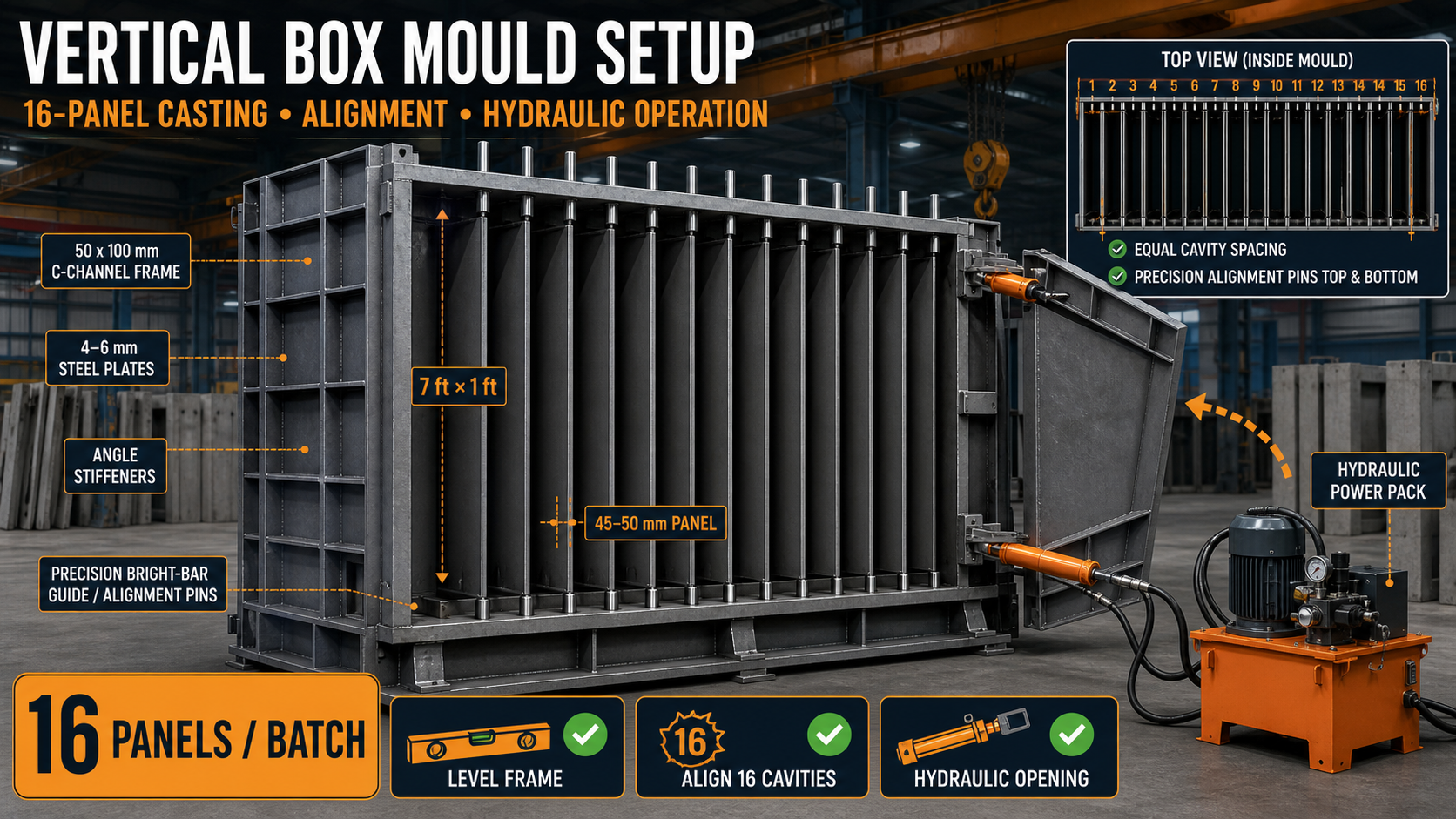
A vertical box mould can manufacture 16 precast boundary wall panels in one casting batch. This guide covers foundation preparation, cavity alignment, hydraulic operation, casting, demoulding and routine inspection.
By Paras Steel Industries ·
Vertical Box Mould Setup Guide: 16-Panel Casting, Alignment and Hydraulic Operation
Vertical Box Mould Setup Guide: 16-Panel Casting, Alignment and Hydraulic Operation
A vertical box mould is a high-output production system used to manufacture multiple precast concrete boundary wall panels in a single casting cycle.
The Vertical Box Mould manufactured by Paras Steel Industries can produce 16 concrete panels per box or batch. Its multi-cavity design uses factory floor space efficiently while supporting consistent panel dimensions and surface quality.
Correct setup is essential because a dimensional error in one divider, guide pin or locking point can affect several panels in the same casting cycle.
This guide explains how to install, align, prepare and operate a 16-panel heavy-duty steel Vertical Box Mould.
Vertical Box Mould Product Specifications
The standard product configuration listed by Paras Steel Industries includes:
Mould type: Concrete precast panel mould
Production capacity: 16 panels per single box or batch
Standard panel length: 7 ft or approximately 2130 mm
Standard panel height: 1 ft or approximately 305 mm
Panel thickness: 45 mm to 50 mm
Main frame: 50 x 100 mm heavy-duty C-channel
Side and base plates: 4 mm to 6 mm high-grade steel plates
Reinforcement structure: 50 x 50 x 6 mm structural steel angle
Guide and alignment pins: Precision bright bar
Operating system: Manual or hydraulic compatible
Panel dimensions and cavity configuration can be customised according to the project requirement.
What Is a Vertical Box Mould?
A Vertical Box Mould contains several narrow casting cavities arranged inside one structural steel box.
Concrete is placed vertically between accurately positioned divider plates. After curing, the box is opened and the individual precast panels are removed.
Unlike separate horizontal panel moulds, a vertical box arrangement produces multiple panels within a compact production area.
The mould is suitable for manufacturing panels used in:
• Residential boundary walls • Agricultural fencing • Farmhouse enclosures • Factory perimeter walls • Warehouse boundaries • School and hospital compounds • Commercial properties • Highway and infrastructure projects • Garden fencing • Land-demarcation walls
Benefits of a 16-Panel Vertical Box Mould
High Output per Casting Cycle
One properly prepared box can produce 16 panels in a single batch.
This reduces the number of separate mould beds required for the same production quantity.
Efficient Use of Factory Space
The cavities are arranged vertically and closely together. This allows manufacturers to achieve higher production from a compact casting area.
Consistent Panel Dimensions
Precision divider plates and alignment pins help maintain panel length, height and thickness across the complete batch.
Reduced Handling Between Moulds
Reinforcement, concrete placement and mould operation are concentrated within one production station.
Manual or Hydraulic Operation
The mould can be configured for manual operation or integrated with a hydraulic opening and closing system.
Custom Panel Configuration
Panel dimensions and cavity specifications can be discussed according to the required boundary wall design.
Main Components of a Vertical Box Mould
A typical Vertical Box Mould includes:
• Structural C-channel base frame • Heavy-duty steel outer shutters • Internal divider plates • Structural angle reinforcement • Guide and alignment pins • Manual or hydraulic closing system • Locks and clamping points • Panel-thickness spacers • Lifting points • Concrete-filling openings • Reinforcement supports • Slurry-control joints • Vibrator mounting arrangements where required
Every component must remain correctly positioned to maintain uniform panel dimensions.
Planning the Installation Area
Before the mould arrives, prepare an installation area with adequate space for:
• Crane unloading • Mould positioning • Outer-shutter opening • Divider removal or movement • Reinforcement placement • Concrete delivery • Hydraulic power-pack access • Panel demoulding • Panel shifting • Cleaning and maintenance • Operator movement
The crane should be able to reach the mould and safely remove the finished panels.
The mould should not be installed next to a wall or machine that blocks its shutters, hydraulic cylinders or maintenance points.
Foundation Requirements
The foundation must support:
• Empty steel mould weight • Sixteen reinforcement assemblies • Fresh concrete load • Divider and shutter loads • Hydraulic operating forces • Vibration • Production personnel and tools • Demoulding and lifting operations
Foundation thickness, reinforcement and anchor-bolt details should be determined according to the mould load and local ground conditions.
The supporting surface should be:
• Firm • Level • Structurally adequate • Properly drained • Free from loose material • Accessible for inspection • Capable of supporting every mould foot
Unstable packing should not be used beneath the mould.
Step 1: Inspect the Mould After Delivery
Before installation, inspect:
• Main frame • Base plates • Outer shutters • Internal divider plates • C-channels • Structural angles • Guide pins • Locking points • Hinges • Hydraulic cylinders • Hoses and fittings • Welded connections • Lifting points • Casting surfaces
Transportation damage should be recorded and corrected before casting begins.
Step 2: Position the Main Frame
Lift the mould only from its approved lifting points using suitable crane and rigging equipment.
Lower it gradually onto the prepared foundation.
Check:
• Correct casting direction • Shutter-opening clearance • Panel-removal direction • Concrete-delivery route • Crane-hook access • Hydraulic power-pack position • Operator access • Cleaning and drainage route
Do not drag the mould across the floor because this may damage or twist the base frame.
Step 3: Level the Base Frame
Levelling should begin from the main structural frame.
Use suitable equipment such as:
• Precision spirit level • Laser level • Surveying instrument • Straightedge • Steel measuring tape • Steel shims • Adjustable supporting feet where provided
Check the level at:
• Four corners • Main frame rails • Centre points • Intermediate supporting feet • Cavity reference locations
A large box mould may be level at its corners but high or low at an intermediate support.
Use stable steel shims or an approved levelling arrangement. Do not use wood, loose bricks or scrap material as permanent supports.
Step 4: Check Frame Squareness
Measure the main frame diagonally from corner to corner.
Record both diagonals and compare them.
If the diagonals differ beyond the approved manufacturing tolerance, inspect:
• Frame position • Supporting feet • Foundation level • Shutter alignment • Anchor-bolt pressure
Do not permanently anchor the mould until its level, position and squareness have been approved.
Step 5: Align the Outer Shutters
Close the outer shutters gradually and check whether they meet the base and end sections uniformly.
Inspect:
• Top alignment • Bottom alignment • Verticality • Joint closure • Lock position • Hinge movement • Contact with guide pins • Hydraulic-cylinder stroke
No shutter should require excessive force to reach its locking position.
Step 6: Align the Internal Divider Plates
Divider alignment controls the thickness and straightness of all 16 panels.
Check every divider for:
• Verticality • Straightness • Equal spacing • Top position • Bottom position • Parallelism • Guide-pin engagement • Casting-surface condition • Contact with end plates • Correct cavity number
Measure cavities at the top, centre and bottom.
A cavity that is correct at the top but wider at the bottom can produce a tapered panel.
Step 7: Verify Panel Thickness
The standard Vertical Box Mould is designed for panel thicknesses between 45 mm and 50 mm, according to the selected configuration.
Measure every casting cavity using a suitable gauge or calibrated template.
Confirm:
• Equal thickness across all cavities • Equal measurements at both ends • Correct spacer arrangement • Secure divider position • No debris between mating surfaces
Hardened concrete or an incorrectly positioned spacer can alter the panel thickness.
Step 8: Check Guide and Alignment Pins
The mould uses precision bright-bar guide and alignment pins.
Inspect each pin for:
• Straightness • Clean surface • Correct engagement • Suitable lubrication where specified • Secure mounting • Wear • Damage • Free movement
A bent or dirty guide pin can prevent proper shutter closure and disturb cavity alignment.
Step 9: Anchor the Mould
After the complete assembly has been levelled and aligned, install or tighten foundation anchors according to the approved installation plan.
Use a balanced tightening sequence.
After anchoring, recheck:
• Frame level • Both diagonals • Shutter alignment • Divider spacing • Panel thickness • Hydraulic operation
Uneven anchor-bolt tightening can pull the frame out of alignment.
Manual Operation
A manually operated Vertical Box Mould may use:
• Screw clamps • Mechanical locks • Wedges • Levers • Guide pins • Removable locking members
Manual operation can provide a simpler and economical setup for moderate production requirements.
Every locking point should be engaged uniformly. Closing one section completely before aligning the others may create uneven pressure.
Hydraulic Operation
Hydraulic integration allows large shutters to open and close using hydraulic cylinders.
A hydraulic system may include:
• Hydraulic power pack • Electric motor • Pump • Oil reservoir • Control valves • Cylinders • Hoses • Fittings • Pressure-control system • Mechanical safety locks
Hydraulic operation can reduce manual effort and improve cycle speed, especially in continuous production.
Pre-Operation Hydraulic Inspection
Before operating the mould, inspect:
• Oil level • Hydraulic hoses • Fittings • Cylinder rods • Mounting pins • Control valves • Electrical connections • Visible leakage • Mechanical stops • Emergency controls
Keep all personnel clear of moving shutters and pinch points.
Hydraulic Opening Procedure
A general opening sequence may include:
1. Confirm that the concrete has achieved approved demoulding strength. 2. Clear the operating area. 3. Remove mechanical safety locks in the specified sequence. 4. Release hydraulic pressure gradually. 5. Open the outer shutters slowly. 6. Observe whether the panels separate uniformly. 7. Stop if any shutter binds or moves unevenly. 8. Secure open shutters against unintended movement. 9. Remove panels using approved lifting points.
Hydraulic force should not be used to break concrete that remains locked to a divider or shutter.
Hydraulic Closing Procedure
A general closing sequence may include:
1. Clean all casting and joint surfaces. 2. Position divider plates correctly. 3. Confirm guide-pin alignment. 4. Operate cylinders slowly. 5. Monitor both sides of the mould. 6. Stop if any component binds. 7. Bring shutters into uniform contact. 8. Engage mechanical locks. 9. Release unnecessary hydraulic pressure where specified. 10. Verify cavity dimensions.
Mechanical locks remain important even where hydraulic cylinders operate the shutters.
Preparing the Mould for Casting
Clean All Casting Surfaces
Remove:
• Hardened concrete • Cement slurry • Dust • Rust • Old sealing material • Excess release agent • Debris around guide pins
Pay particular attention to cavity bottoms and divider joints.
Apply Release Agent
Apply a thin and uniform layer of suitable mould release agent.
Avoid excess material because it may:
• Collect at cavity bottoms • Stain the concrete • Contaminate reinforcement • Affect joint sealing • Create surface defects
Install Reinforcement
Prepare reinforcement according to the approved panel drawing.
Check:
• Bar or mesh dimensions • Concrete cover • Reinforcement straightness • Cavity clearance • Lifting inserts • Connection details • Spacer positions
The reinforcement should not touch the steel casting plates.
Final Pre-Pour Inspection
Before placing concrete, verify:
• Main frame level • All 16 cavities clean • Divider plates aligned • Cavity thickness correct • Guide pins engaged • Hydraulic shutters closed • Mechanical locks secured • Reinforcement correctly positioned • Release agent uniformly applied • Joints properly sealed • Concrete delivery equipment ready • Vibrators securely installed where applicable
16-Panel Concrete Casting Process
Concrete should be distributed according to a controlled sequence.
The aim is to keep concrete pressure balanced across the box.
A practical process includes:
1. Confirm approved concrete workability. 2. Begin filling cavities in the planned sequence. 3. Distribute concrete uniformly. 4. Avoid completely filling one side while the other remains empty. 5. Monitor divider movement. 6. Compact concrete according to the approved vibration method. 7. Observe joints for slurry leakage. 8. Maintain the required top level. 9. Finish exposed surfaces. 10. Begin curing promptly.
The exact pouring sequence should be established during trial production and documented for operators.
Why Balanced Filling Is Important
Uneven filling can apply greater pressure to one side of an internal divider.
This may cause:
• Divider movement • Unequal panel thickness • Frame stress • Joint opening • Slurry leakage • Surface variation
Balanced filling reduces differential pressure between neighbouring cavities.
Concrete Vibration
Concrete must flow around reinforcement and fill narrow panel cavities without honeycombing.
Possible vibration systems include:
• Shutter vibrators • External vibrators • Carefully controlled internal vibration • A combined system
Avoid excessive vibration because it can cause:
• Concrete segregation • Divider movement • Loose locks • Slurry leakage • Surface staining • Uneven aggregate distribution
Vibrator type, location and operating duration should match the mould and concrete mix.
Curing and Demoulding
The panels should remain inside the box until the concrete achieves the approved stripping strength.
Demoulding time depends on:
• Concrete mix • Cement type • Temperature • Curing method • Panel thickness • Required handling strength • Production procedure
Do not open the mould according to elapsed time alone.
16-Panel Demoulding Process
A controlled demoulding sequence may include:
1. Confirm stripping strength. 2. Prepare crane and panel-handling equipment. 3. Clear the operating area. 4. Release locks gradually. 5. Open outer shutters. 6. Check panel separation. 7. Release dividers according to the mould design. 8. Connect approved lifting equipment. 9. Remove panels individually. 10. Place panels on suitable supports. 11. Inspect finished dimensions. 12. Continue the required curing. 13. Clean the mould immediately.
Do not allow finished panels to strike the divider plates during removal.
Panel Quality Inspection
Inspect panels from different cavity positions.
Check:
• Length • Height • Thickness • Squareness • Straightness • Surface finish • Edge quality • Reinforcement cover • Insert positions • Honeycombing • Slurry-loss marks • Cracks • Cavity identification
Recording defects by cavity number helps identify a specific divider or joint requiring adjustment.
Common Setup Problems
Unequal Panel Thickness
Possible causes:
• Incorrect divider spacing • Worn guide pins • Debris in joints • Loose locking points • Uneven concrete pressure
Tapered Panels
Possible causes:
• Divider not vertical • Different spacing at top and bottom • Base frame not level • Bent internal plate
Slurry Leakage
Possible causes:
• Dirty contact surfaces • Damaged seals • Loose locks • Distorted plates • Unbalanced filling
Difficult Hydraulic Operation
Possible causes:
• Low oil level • Air in the system • Bent mounting pin • Misaligned shutter • Damaged cylinder • Contaminated hydraulic oil
Panels Sticking to Dividers
Possible causes:
• Insufficient release agent • Dirty casting surface • Damaged divider plate • Premature demoulding • Incorrect opening sequence
Daily Maintenance Checklist
Before Casting:
• Clean all cavities • Inspect divider plates • Check guide pins • Check hydraulic hoses • Confirm oil level • Test locks and shutters • Verify cavity spacing • Inspect seals • Apply release agent
After Demoulding:
• Remove concrete residue • Clean cavity bottoms • Check slurry-leakage marks • Inspect guide-pin wear • Examine welded joints • Check hydraulic leakage • Inspect locks and hinges • Record damaged cavity locations
Periodic Inspection:
• Verify frame level • Measure diagonals • Measure all cavity widths • Check divider straightness • Inspect C-channels and angles • Tighten suitable fasteners • Service hydraulic components • Repair damaged coating • Inspect lifting points
Production Capacity
One Vertical Box Mould produces 16 panels per batch.
A simplified output calculation is:
Daily Panel Output = Number of Vertical Box Moulds × Casting Cycles per Day × 16 Panels
Actual output also depends on:
• Concrete mixing capacity • Reinforcement preparation • Filling time • Vibration • Curing • Demoulding strength • Crane availability • Panel storage • Labour • Cleaning time
The mould quantity should be planned according to the complete production cycle.
Manual vs Hydraulic Selection
Manual operation may suit:
• Moderate production • Lower initial investment • Plants with available labour • Simpler maintenance requirements
Hydraulic operation may suit:
• High daily production • Frequent mould operation • Large shutters • Reduced manual effort • Faster opening and closing
The hydraulic system should be selected according to mould weight, shutter movement and production frequency.
Buying Checklist
Before ordering a Vertical Box Mould, confirm:
• Required panel length • Required panel height • Panel thickness • Number of cavities • Steel plate thickness • Main frame section • Divider construction • Guide-pin material • Manual or hydraulic operation • Concrete vibration method • Required daily output • Factory-space availability • Crane capacity • Foundation arrangement • Custom insert requirements • Surface-finish requirement
Final Conclusion
A Vertical Box Mould provides high-output production by manufacturing 16 precast boundary wall panels in a single box casting batch.
Its performance depends on correct foundation preparation, base-frame levelling, divider alignment, guide-pin condition and uniform cavity spacing.
Balanced concrete filling, controlled vibration and verified demoulding strength help protect panel dimensions and surface quality.
Hydraulic operation can reduce manual effort and improve production speed, but mechanical locks, alignment checks and regular maintenance remain essential.
Paras Steel Industries manufactures heavy-duty Vertical Box Moulds using 50 x 100 mm C-channels, 4 mm to 6 mm high-grade steel plates, 50 x 50 x 6 mm structural angles and precision bright-bar alignment pins.
The standard mould supports 16 panels of approximately 7 ft x 1 ft with a thickness of 45 mm to 50 mm. Custom dimensions and configurations can be discussed according to project requirements.
For specifications and pricing, share your panel dimensions, daily production target, available factory space and preferred manual or hydraulic operating system with Paras Steel Industries.