
Precast Mould Maintenance Guide
Vertical Box Mould Hydraulic Hose Maintenance: Routing, Leakage and Pressure-Loss Troubleshooting
Hydraulic hoses control the opening and closing movement of a vertical box mould. Poor routing, oil leakage, damaged fittings or restricted flow can cause uneven shutter movement, pressure loss and production delays. This guide explains safe hose inspection, routing, leakage detection and preventive maintenance for heavy-duty iron vertical box moulds.
By Paras Steel Industries ·
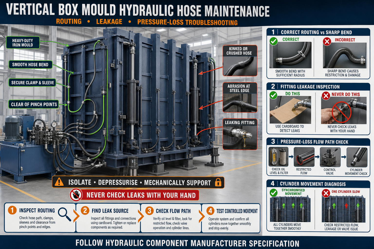
Vertical Box Mould Hydraulic Hose Maintenance: Routing, Leakage and Pressure-Loss Troubleshooting
Vertical Box Mould Hydraulic Hose Maintenance: Routing, Leakage and Pressure-Loss Troubleshooting
A hydraulic system makes it easier to open, close and operate the shutters of a heavy-duty vertical box mould. Hydraulic hoses carry pressurised oil between the power pack, control valve and cylinders.
Although hoses appear to be simple components, incorrect routing, damaged outer covers, loose fittings or internal restrictions can affect the complete mould operation. These problems may cause uneven shutter movement, slow operation, oil leakage and unexpected production stoppages.
Regular hydraulic hose maintenance helps protect the cylinders, valves, iron mould structure and production team.
Role of Hydraulic Hoses in a Vertical Box Mould
A hydraulic vertical box mould may use one or multiple cylinders to move its shutters. Hydraulic hoses transfer oil to and from these cylinders according to the selected operating direction.
The hose arrangement may connect:
• Hydraulic power pack • Oil reservoir • Pump and motor unit • Direction-control valve • Flow-control components • Hydraulic cylinders • Return line • Pressure-relief arrangement • Filter and other approved accessories
The exact circuit depends on the mould design. Maintenance should always follow the hydraulic drawing and component manufacturer’s instructions.
Why Correct Hydraulic Hose Routing Is Important
Correct routing allows hoses to move naturally without rubbing, stretching or becoming trapped between mould components.
Poor hose routing can cause:
• Abrasion against the iron mould frame • Sharp bending near hose fittings • Hose stretching during shutter movement • Twisting of the hose body • Contact with moving hinges or locks • Crushing between shutters and structural members • Excessive vibration • Heat exposure • Premature hose failure • Sudden oil leakage
The hose route should accommodate the complete opening and closing stroke of the mould.
Hydraulic Hose Routing Checklist
Inspect the complete hose path while the system is safely isolated and depressurised.
Check the following points:
• Hoses have sufficient length for the full cylinder stroke • No hose is stretched during shutter opening • Hoses do not form excessively sharp bends • The hose body is not twisted • Fittings are not carrying the hose’s weight • Hoses remain clear of hinges, clamps and locking mechanisms • Suitable clamps or supports are installed • Protective sleeves are used at possible rubbing points • Hoses cannot become trapped during mould closing • Connections match the approved hydraulic circuit • Moving hoses have enough controlled flexibility
Do not secure a hose so tightly that it cannot move naturally during cylinder operation.
Maintain a Suitable Bend Radius
Every hydraulic hose has a specified minimum bend radius. Bending it more sharply can damage the reinforcement layers and restrict oil flow.
Sharp bending commonly occurs near fittings when:
• The hose length is incorrect • The fitting orientation is unsuitable • The hose is pulled sideways • Supporting clamps are positioned incorrectly • A straight fitting is used where an approved angled fitting is needed
Always follow the hose manufacturer’s bend-radius requirements.
Avoid Hose Twisting
A twisted hose may look acceptable while the mould is stationary but can become highly stressed when the cylinder moves.
Check the printed identification line along the hose, where available. A spiralling line may indicate that the hose has been twisted during installation.
To prevent twisting:
• Hold the hose in its natural position • Align the fittings before tightening • Do not rotate the hose body to match a connection • Use suitable fitting orientations • Observe the hose during the full shutter movement
How to Inspect Hydraulic Hoses Safely
Hydraulic systems can retain dangerous pressure even after the pump is switched off. Never inspect a suspected leak with bare hands.
Before inspection:
• Stop the hydraulic power pack • Isolate electrical power according to the plant procedure • Release stored hydraulic pressure safely • Support or mechanically secure movable shutters • Clean the work area • Wear suitable eye and hand protection • Follow the mould and hydraulic-system instructions
Never work beneath or between shutters that are supported only by hydraulic pressure.
Visual Hose Inspection
Inspect every hose from one fitting to the other.
Look for:
• Cracks in the outer cover • Cuts or deep scratches • Abrasion and exposed reinforcement • Blisters or bubbles • Flattened or crushed sections • Kinking • Oil-soaked areas • Corrosion near fittings • Loose clamps • Hose movement marks • Damaged protective sleeves • Incorrectly installed fittings
A hose with exposed reinforcement, severe kinking, blistering or fitting damage should not remain in service.
Common Hydraulic Leakage Locations
Oil leakage may occur at several points in the system.
Typical locations include:
• Hose-to-fitting connection • Crimped hose end • Threaded adapter • Control-valve port • Cylinder port • Cylinder rod seal • Pump connection • Filter housing • Oil reservoir connection
Clean the suspected area before inspection. Old oil and concrete dust can make it difficult to identify the actual leak source.
Never Search for a Leak With Your Hand
A small hydraulic leak may release a fine, high-pressure oil jet that is difficult to see. This can penetrate skin and cause a serious medical emergency.
Use an approved safe inspection method, such as a suitable piece of cardboard, while remaining clear of the suspected leak path. Shut down and depressurise the system before tightening or replacing components.
Causes of Hydraulic Hose Leakage
Common causes include:
• Loose or incorrectly tightened fittings • Damaged sealing surfaces • Incorrect fitting type • Damaged hose crimp • Excessive pressure • Hose abrasion • Improper bend radius • Hose twisting • Vibration at unsupported connections • Contaminated sealing faces • Age-related deterioration • Heat or chemical exposure • Physical impact during mould cleaning
Replacing only the leaking hose without correcting the underlying cause may result in repeated failure.
What Is Hydraulic Pressure Loss?
Pressure loss means the hydraulic system cannot deliver the required force or controlled movement at the cylinder.
Possible symptoms include:
• Slow shutter opening • Incomplete cylinder stroke • Uneven movement between shutters • Cylinder movement stopping under load • Pump operating for longer than normal • Excessive oil temperature • Unusual pump noise • Jerky or unstable movement • Reduced clamping or opening performance
These symptoms do not always mean that the hose is defective. The complete hydraulic circuit should be checked systematically.
Hydraulic Pressure-Loss Troubleshooting
1. Check the Oil Level
Low hydraulic oil can allow air to enter the system and reduce operating performance. Use only the approved oil type and filling procedure.
2. Inspect for External Leakage
Check hoses, fittings, valves, cylinder seals and the power pack for visible oil loss.
3. Examine the Hose Route
A crushed, kinked or sharply bent hose can restrict oil flow. Inspect the hose through the full mould movement.
4. Check the Filter
A blocked hydraulic filter can restrict flow and increase pressure drop. Inspect or replace it according to the maintenance schedule.
5. Inspect the Suction Line
A loose or damaged suction connection may allow air to enter the pump. Foamy oil and irregular noise can indicate aeration.
6. Check the Control Valve
A sticking or contaminated control valve may restrict oil flow or prevent full pressure from reaching the cylinder.
7. Inspect the Pressure-Relief Setting
An incorrectly operating relief valve may divert oil before the cylinder receives the required pressure. Adjustment should only be performed by authorised personnel using approved specifications.
8. Check Cylinder Condition
Internal seal leakage inside a cylinder can cause slow movement or an inability to hold position, even when no external leak is visible.
9. Compare Cylinder Movement
On a multi-cylinder mould, compare the movement of both sides. Uneven movement may result from restricted flow, trapped air, unequal loading or cylinder-related problems.
10. Use Approved Test Equipment
Pressure testing should be performed by trained personnel using correctly rated gauges and the manufacturer’s specified test points. Never guess the required pressure setting.
Why Vertical Box Mould Shutters Move Unevenly
Uneven hydraulic movement can twist the mould shutters and affect cavity alignment.
Possible causes include:
• Different hose lengths or restrictions • One kinked or damaged hose • Air trapped in one side of the circuit • Unequal flow-control settings • Internal cylinder leakage • Mechanical binding at hinges • Slurry buildup around moving components • Incorrect cylinder mounting • One shutter carrying more resistance • Damaged or misaligned iron mould structure
The hydraulic system and mechanical mould structure should both be inspected before making adjustments.
How to Prevent Hose Abrasion
Hydraulic hoses installed close to the iron mould structure may rub against sharp edges during repeated operation.
Preventive measures include:
• Installing suitable hose clamps • Using protective sleeves • Providing smooth hose guides • Removing contact with sharp plate edges • Maintaining controlled movement loops • Separating hoses from chains and locking parts • Checking hose movement during a slow trial cycle
Protective sleeves reduce external wear but do not correct poor routing.
Hydraulic Hose Replacement Guide
Replace a hose when it shows serious damage or no longer meets the approved operating requirement.
Before replacement:
• Identify the hose correctly • Record its connection points • Confirm hose size and length • Check pressure and temperature ratings • Match the approved fitting type • Clean the surrounding ports • Cap open connections against contamination • Route the new hose without twisting • Tighten connections according to approved instructions • Restore oil level if required • Inspect for leaks during a controlled test
Never replace a hydraulic hose with an unverified pipe, low-pressure hose or improvised connection.
Importance of Hydraulic Oil Cleanliness
Dirty hydraulic oil can damage pumps, valves, cylinder seals and hose components.
Common contamination sources include:
• Open hose connections • Dirty filling containers • Concrete dust • Water entry • Worn seals • Damaged reservoir breather • Metal particles from component wear
Keep hose ends and hydraulic ports capped during maintenance. Use clean tools and the approved oil-handling procedure.
Daily Hydraulic Hose Inspection
Before starting production:
• Check the floor for fresh oil • Inspect visible hoses and fittings • Confirm protective sleeves are in position • Check that hoses are clear of moving shutters • Observe shutter movement from a safe position • Listen for unusual pump noise • Check for jerky or uneven cylinder movement • Confirm that no hose is stretched or trapped • Report leakage immediately
Do not continue operating the mould when a hose shows severe damage or active leakage.
Periodic Maintenance Checklist
At scheduled intervals:
• Clean the hydraulic power pack • Inspect all hoses throughout their length • Check fitting security • Inspect hose clamps and supports • Examine cylinder rods and seals • Check the reservoir oil level • Inspect the filter indicator • Check the reservoir breather • Review hose movement during operation • Inspect the iron mould’s cylinder mounting brackets • Confirm mechanical stops and safety supports • Record replaced hoses and recurring leakage points
Maintenance records help identify repeated failures and improve the hose-routing design.
Common Maintenance Mistakes
Ignoring Minor Oil Leakage
A small leak can develop into a larger failure and collect dust around the mould.
Tightening Fittings Under Pressure
Hydraulic connections should never be tightened while the system is pressurised.
Using Incorrect Replacement Hoses
A visually similar hose may not have the correct pressure, temperature or fluid compatibility.
Allowing Hoses to Rub Against Iron Edges
Repeated rubbing gradually removes the outer cover and exposes the reinforcement.
Depending Only on Hydraulic Pressure for Support
Hydraulic pressure is not a substitute for an approved mechanical safety support.
Adjusting Pressure Without Diagnosis
Increasing system pressure may hide the original problem and overload hoses, cylinders or the mould structure.
Operating With Damaged Hoses
A damaged hose can fail suddenly. Replacement should not be delayed when rejection criteria are met.
Benefits of Proper Hydraulic Hose Maintenance
Regular maintenance provides:
• Smooth shutter opening and closing • Reduced oil leakage • More consistent cylinder movement • Better vertical box mould alignment • Lower risk of unexpected hose failure • Reduced production downtime • Longer hydraulic-component life • Cleaner factory operation • Improved maintenance safety • More reliable precast panel production
Conclusion
Hydraulic hose maintenance is essential for reliable operation of a vertical box mould. Correct routing prevents abrasion, twisting, sharp bending and hose trapping, while regular inspection helps identify leakage before it causes a breakdown.
Pressure loss should be diagnosed systematically by inspecting the oil level, hoses, filters, valves, cylinders and mechanical mould movement. Operators should never search for hydraulic leaks with bare hands or work around unsupported shutters.
A clean hydraulic circuit, properly routed hoses and a well-maintained heavy-duty iron vertical box mould help deliver smooth operation, accurate panel production and fewer unexpected stoppages.