
Precast Mould Guide
Vertical Box Mould Hydraulic Cylinder Synchronization: Uneven Opening, Stroke Matching and Seal Inspection
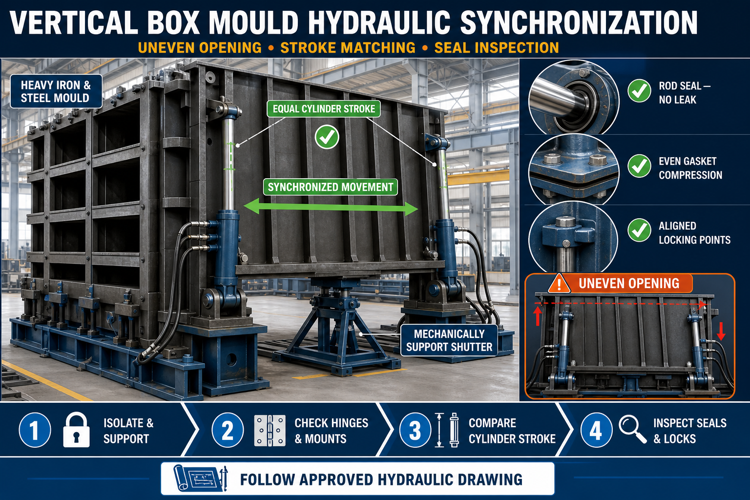
Uneven hydraulic-cylinder movement can twist vertical box mould shutters, damage seals and affect panel dimensions. This guide explains how to inspect cylinder synchronization, compare shutter stroke, identify oil leakage and restore balanced opening safely.
By Paras Steel Industries ·
Vertical Box Mould Hydraulic Cylinder Synchronization: Uneven Opening, Stroke Matching and Seal Inspection
Vertical Box Mould Hydraulic Cylinder Synchronization Guide
A vertical box mould allows precast manufacturers to cast multiple concrete wall panels in an upright arrangement. Its heavy iron shutters may be opened and closed using a hydraulic system to reduce manual handling and support consistent production.
For correct operation, all connected hydraulic cylinders must move in a controlled and coordinated manner. If one cylinder extends or retracts faster than another, the shutter may open unevenly, twist against its hinges or place excessive pressure on the locking and sealing system.
This guide explains vertical box mould hydraulic synchronization, including uneven-opening diagnosis, cylinder stroke matching, seal inspection and safe maintenance practices.
What Is Hydraulic Cylinder Synchronization?
Hydraulic cylinder synchronization means coordinating two or more cylinders so that the connected mould shutter moves evenly.
A synchronized system should provide:
• Balanced shutter movement • Controlled opening and closing • Similar cylinder travel • Reduced shutter twisting • Stable flange contact • Reliable seal compression • Lower stress on hinges and brackets • Safer mould operation
The hydraulic arrangement may use flow-control valves, flow dividers, mechanical linkages, electronic controls or another approved system. The correct method depends on the mould and hydraulic-power-pack design.
Why Uneven Cylinder Movement Is a Problem
A heavy vertical box mould shutter should remain aligned throughout its movement. If one end opens before the other, the shutter can become skewed.
Uneven movement may cause:
• Shutter twisting • Cylinder-rod side loading • Damaged hydraulic seals • Oil leakage • Bent pins or brackets • Uneven gasket compression • Slurry leakage • Difficulty engaging locks • Mould dimensional variation • Abnormal noise • Increased maintenance requirements
Severe misalignment can create an unsafe operating condition and should not be ignored.
Main Components of the Hydraulic System
A typical hydraulic opening system may include:
• Hydraulic power pack • Electric motor • Hydraulic pump • Oil reservoir • Control valves • Flow-control arrangement • Hydraulic cylinders • Pressure-relief valve • Hoses and pipes • Filters • Pressure gauge • Pins and mounting brackets • Mechanical stops • Shutter hinges • Operating controls
Every component must match the approved hydraulic design.
Safety Before Inspection
Hydraulic systems can retain pressure even after the power supply has been switched off. Heavy iron shutters can also move unexpectedly if pressure is released incorrectly.
Before inspection:
1. Stop mould operation. 2. Disconnect and isolate the electrical supply. 3. Apply the plant’s lockout and tagout procedure. 4. Lower or secure the shutters in a stable position. 5. Release stored hydraulic pressure through the approved procedure. 6. Support heavy moving components mechanically. 7. Keep personnel outside the shutter movement zone. 8. Wear suitable personal protective equipment. 9. Allow only trained personnel to inspect the hydraulic system.
Never rely only on hydraulic pressure to hold a heavy shutter during maintenance.
Signs of Poor Hydraulic Synchronization
Common warning signs include:
• One end of the shutter moves first • One cylinder reaches its limit before the other • The shutter opens diagonally • Movement is jerky or intermittent • Cylinder rods extend by visibly different amounts • Locks are difficult to engage • Flange gaps vary from top to bottom • Hydraulic hoses move excessively • Oil temperature rises abnormally • The power pack produces unusual noise • A cylinder continues drifting after stopping • Seals repeatedly begin leaking
Stop the system if the shutter becomes severely misaligned.
Begin With a Visual Inspection
Before adjusting valves or replacing components, inspect the complete mould and hydraulic system.
Check:
• Shutter hinges • Cylinder mounting brackets • Cylinder pins • Rod-end connections • Hydraulic hoses • Oil leakage • Locking mechanisms • Mechanical stops • Mould-base level • Flange cleanliness • Sealing gaskets • Welded joints • Shutter distortion
A mechanical obstruction can appear to be a hydraulic synchronization problem.
Check the Mould Foundation and Frame
Cylinder synchronization cannot compensate for a twisted mould frame or uneven foundation.
Inspect:
• Base-frame level • Contact at all support points • Anchor condition • Structural distortion • Loose frame connections • Cracked welds • Concrete buildup beneath the mould • Alignment of the main iron shutters
Correct structural or foundation problems before adjusting the hydraulic system.
Inspect Shutter Hinges and Pins
A seized or misaligned hinge can make one cylinder work harder than another.
Check hinges for:
• Hardened concrete or slurry • Corrosion • Bent hinge pins • Insufficient lubrication • Unequal clearances • Worn bushes • Cracked mounting brackets • Poor hinge alignment • Metal-to-metal binding
Clean and lubricate hinge components using the approved maintenance procedure.
Check Cylinder Mounting Alignment
Hydraulic cylinders should operate in line with their intended movement. Side loading can damage the rod, seals and mounting brackets.
Inspect:
• Cylinder-body alignment • Rod-end alignment • Pin condition • Bush wear • Bracket position • Weld condition • Mounting clearance • Contact during full movement • Signs of rod scoring
A cylinder should not be forced sideways to compensate for a misaligned shutter.
Cylinder Stroke Matching
Stroke matching checks whether connected cylinders travel the required distance together.
A basic controlled inspection may include:
1. Secure and prepare the empty mould. 2. Establish fixed measurement points. 3. Mark matching reference positions. 4. Operate the shutters slowly. 5. Pause at selected points during travel. 6. Compare both cylinder positions. 7. Check shutter alignment at each position. 8. Record the differences. 9. Repeat during closing. 10. Compare the results with the approved system requirement.
Do not measure one cylinder from the previous cylinder. Use the same fixed datum for every reading.
Partial-Stroke Checks
Only comparing the cylinders at full extension may hide a synchronization problem occurring during movement.
Compare the cylinder positions at:
• Initial movement • Intermediate positions • Near full opening • Full approved opening • Initial closing • Intermediate closing • Fully closed position
The actual checking points should follow the hydraulic and mould manufacturer’s procedure.
Check for Mechanical Stops
Mechanical stops define the final shutter position and protect components from overtravel.
Inspect:
• Stop position • Contact on both sides • Loose fasteners • Worn contact surfaces • Bent stop plates • Weld condition • Unequal stop engagement
Hydraulic cylinders should not be used to force the shutter beyond its designed mechanical limit.
Inspect Hydraulic Oil
Contaminated or unsuitable hydraulic oil can cause valves and cylinders to move inconsistently.
Check:
• Oil level • Oil cleanliness • Signs of water contamination • Foam or air bubbles • Unusual colour • Burnt smell • Metal particles • Recommended oil grade • Maintenance and replacement records
Use only the hydraulic oil specified by the equipment manufacturer. Do not mix incompatible oils.
Air Inside the Hydraulic System
Air in hydraulic lines can cause jerky movement, noise and inconsistent cylinder travel.
Possible signs include:
• Spongy movement • Sudden speed changes • Foaming in the reservoir • Irregular cylinder response • Unusual pump noise • Delayed movement
Air should be removed only through the approved bleeding procedure. Incorrect bleeding can release pressurized oil and create an injury risk.
Inspect Hydraulic Hoses and Pipes
Flow restriction in one cylinder line can create unequal movement.
Check hoses and pipes for:
• Kinks • Crushing • Internal collapse • Sharp bends • External damage • Oil leakage • Loose fittings • Incorrect routing • Contact with moving shutters • Different line configurations • Heat damage
Replace damaged hydraulic hoses with components matching the approved pressure and system requirements.
Check Flow-Control Valves
Flow-control valves regulate the oil supplied to or returned from each cylinder. Incorrect adjustment or contamination can cause speed differences.
Qualified personnel should inspect:
• Valve settings • Direction of installation • Internal contamination • Damaged adjustment controls • Loose fittings • Blocked passages • Valve response • Matching flow to connected cylinders
Valve settings should follow the approved hydraulic circuit. Do not adjust them through guesswork.
Flow Divider Inspection
Some systems use a flow divider to distribute oil between multiple cylinders.
A synchronization problem may occur if the divider is:
• Contaminated • Worn internally • Incorrectly selected • Installed incorrectly • Receiving aerated oil • Operating outside its approved range
The component should be inspected according to its manufacturer’s instructions.
Internal Cylinder Leakage
A cylinder may leak internally even if no oil is visible outside. Worn internal seals can allow oil to bypass the piston, causing slow movement or cylinder drift.
Possible symptoms include:
• One cylinder moves more slowly • One shutter end drifts after stopping • Cylinder position changes under load • The power pack runs longer • Synchronization repeatedly changes • External components appear normal
Internal leakage testing must be performed by qualified hydraulic technicians using an approved procedure.
External Seal Inspection
Inspect the cylinder for visible oil around:
• Rod seal • Cylinder head • Port connections • Hose fittings • End caps • Welded body areas
Also inspect the rod for:
• Scratches • Pitting • Rust • Bent condition • Concrete contamination • Damaged surface coating
A damaged rod surface can quickly wear a new seal.
Never Search for Hydraulic Leaks With Bare Hands
Pressurized hydraulic oil can penetrate the skin and cause serious injury.
When checking for leaks:
• Isolate the system where required • Use approved inspection methods • Keep hands away from suspected leaks • Wear eye and hand protection • Replace damaged hoses and fittings • Seek immediate medical attention for any injection injury
Do not tighten pressurized fittings.
Check the Hydraulic Filter
A blocked filter can restrict oil flow and affect system performance.
Inspect:
• Filter condition • Clogging indicator • Replacement record • Contamination inside the filter • Bypass condition • Correct filter type
Frequent filter blockage may indicate contamination entering the reservoir or wear inside the system.
Power-Pack Inspection
The hydraulic power pack supplies flow and pressure to the cylinders.
Check:
• Pump noise • Motor operation • Oil temperature • Reservoir cleanliness • Suction-line condition • Filter condition • Valve operation • Pressure-gauge behaviour • Mounting bolts • Electrical connections
Electrical inspection must be carried out by qualified personnel.
Seal Inspection at Mould Flanges
Hydraulic synchronization affects how evenly the mould shutters close against the flange seals.
Inspect the sealing system for:
• Uneven gasket compression • Crushed seal sections • Missing gasket material • Hardened or cracked seals • Concrete and slurry deposits • Gaps at corners • Loose seal retainers • Misaligned flange surfaces • Oil contamination
Replace damaged seals with compatible material according to the mould design.
Uneven Seal Compression
If the top of a shutter closes before the bottom, or one end closes before the other, the gasket may be compressed unevenly.
This can cause:
• Slurry leakage • Concrete fins • Difficult lock engagement • Premature seal wear • Shutter distortion • Inconsistent panel dimensions
Cylinder synchronization, hinge alignment and mechanical-stop positions should all be checked.
Check the Locking System
Hydraulic cylinders should position the shutter, while the approved locking system secures it during concrete casting.
Inspect:
• Locking clamps • Wedges • Pins • Bolts • Lock brackets • Contact surfaces • Alignment at each lock • Wear and deformation • Concrete buildup
Do not depend solely on hydraulic pressure to resist fresh concrete pressure unless the system was specifically designed and approved for that purpose.
Controlled Synchronization Test
After completing inspection and repairs, perform a controlled test without concrete.
The test should include:
1. Clear the operating area. 2. Reinstall all required guards. 3. Confirm that tools have been removed. 4. Operate the power pack at the approved setting. 5. Move the shutter slowly. 6. Observe both cylinders. 7. Pause at selected positions. 8. Compare stroke and shutter alignment. 9. Check for leaks and abnormal noise. 10. Close the shutter gradually. 11. Inspect seal compression. 12. Confirm lock alignment. 13. Record the test result.
Stop immediately if jerky movement, leakage or severe misalignment continues.
Common Problems and Possible Causes
One Cylinder Moves Faster
Possible causes include unequal valve settings, internal leakage, different flow restrictions, air in the system or unequal mechanical resistance.
One Cylinder Stops Before the Other
Check mechanical stops, cylinder stroke, shutter obstruction, valve operation and mounting alignment.
Shutter Opens With a Twist
Inspect hinge alignment, base-frame level, cylinder synchronization, mounting brackets and shutter distortion.
Jerky Cylinder Movement
Possible causes include air in the oil, contamination, damaged seals, binding hinges or inconsistent pump flow.
Cylinder Drifts After Stopping
Internal seal leakage, valve leakage or an external oil leak may be responsible.
Oil Leaks From the Rod Seal
Inspect the rod for scoring, contamination, misalignment or side loading before replacing the seal.
Locks Do Not Align After Closing
Check stroke matching, mechanical stops, hinge wear, gasket compression and mould-frame alignment.
Slurry Leaks From One End
Possible causes include uneven shutter closing, damaged seals, dirty flanges, misaligned locks or structural distortion.
Maintenance Checklist
Daily Checks
• Inspect visible oil leakage • Clean concrete from hinges and locks • Check hose condition • Observe cylinder movement • Listen for abnormal pump noise • Inspect shutter alignment • Check seal contact
Scheduled Checks
• Compare cylinder stroke • Inspect rod surfaces • Check mounting pins and bushes • Examine welded brackets • Inspect hydraulic oil • Service filters • Check valves and flow divider • Inspect flange seals • Test mechanical stops • Record synchronization results
Maintenance frequency should follow operating conditions and the hydraulic-system manufacturer’s recommendations.
When Should the Mould Be Stopped?
Stop hydraulic operation if you observe:
• Severe uneven shutter movement • Sudden cylinder drift • Pressurized oil leakage • Damaged hoses • Bent cylinder rods • Cracked mounting brackets • Loose cylinder pins • Repeated power-pack overheating • Abnormal pump noise • Shutter movement after control release • Failed mechanical supports • Locks that cannot engage correctly
Production should resume only after the fault has been corrected and the system has passed a controlled test.
Conclusion
Vertical box mould hydraulic synchronization is essential for balanced shutter opening, correct seal compression and reliable locking.
Uneven movement may result from hydraulic flow differences, air contamination, internal cylinder leakage, damaged seals, worn hinges or structural misalignment. Troubleshooting should therefore cover both the hydraulic system and the heavy iron mould structure.
Paras Steel Industries manufactures heavy-duty iron and structural-steel precast moulds according to customer requirements and approved drawings. Proper cylinder synchronization, regular seal inspection and planned hydraulic maintenance can support safer operation and consistent precast panel production.