
Precast Mould Guide
U Drain Mould Joint Former Setup: Tongue-and-Groove Alignment, Sealing and Demoulding Guide
Joint formers create the tongue-and-groove ends that help precast U drains align during installation. Incorrect former positioning, damaged seals or poor demoulding can produce joint gaps, leakage paths and broken concrete edges. This guide explains alignment, fastening, sealing and safe removal of joint formers in heavy-duty iron U drain moulds.
By Paras Steel Industries ·
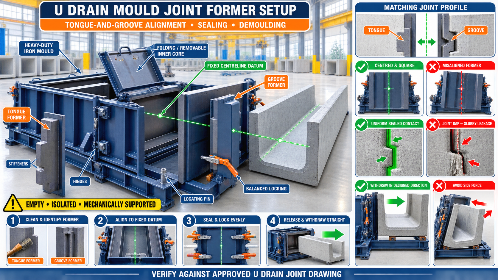
U Drain Mould Joint Former Setup: Tongue-and-Groove Alignment, Sealing and Demoulding Guide
U Drain Mould Joint Former Setup: Tongue-and-Groove Alignment, Sealing and Demoulding Guide
Precast U drains are commonly installed in a continuous line for stormwater, industrial drainage and infrastructure projects. The joint between two drain units plays an important role in their alignment and installation quality.
A tongue-and-groove joint helps adjoining U drain units locate against each other. This profile is created inside the heavy-duty iron mould using accurately positioned joint formers.
If a former is misaligned, loose or improperly sealed, the finished drain may have uneven joint faces, concrete fins, slurry leakage or damaged edges. Correct joint-former setup helps produce repeatable profiles and smoother site installation.
What Is a U Drain Joint Former?
A joint former is a removable iron or steel component that creates the required profile at the end of a precast U drain.
Depending on the product drawing, the arrangement may include:
• Tongue-forming insert • Groove-forming insert • End shutter • Profile plate • Tapered removable section • Alignment pins • Guide blocks • Bolted or clamped connections • Sealing strip • Release arrangement • Lifting or handling points
The former design should match the approved U drain joint drawing.
Understanding Tongue-and-Groove Joints
A tongue-and-groove joint uses two complementary profiles.
Tongue
The tongue is a projecting profile formed at one end of the drain.
Groove
The groove is a recessed profile formed at the corresponding end.
During installation, the tongue enters the groove of the adjoining unit. This helps establish alignment and control movement between units.
The joint profile may support positioning, but it should not automatically be treated as a watertight connection. Final sealing requirements depend on the project design.
Why Joint-Former Accuracy Is Important
Accurate joint formers help achieve:
• Consistent drain length • Correct tongue position • Correct groove position • Matching joint faces • Reduced installation gaps • Straight drain alignment • Cleaner concrete edges • Easier demoulding • Lower product rejection • Repeatable production
Errors in the mould are repeated in every U drain manufactured before correction.
Common Joint-Former Problems
Common production problems include:
• Tongue and groove not matching • Joint profile positioned off-centre • Former installed at an angle • Uneven joint depth • Excessive concrete fins • Slurry leakage • Damaged concrete edges • Former sticking during demoulding • Incorrect drain length • Cracks near the joint • Former movement during vibration • Worn alignment pins
The underlying cause should be identified before adjusting the locks or adding temporary packing.
Components of a Joint-Former System
A typical joint-former arrangement may contain:
End Shutter
The end shutter closes the U drain mould and supports the joint-forming component.
Profile Insert
The profile insert produces the required tongue or groove shape.
Locating Pins
Locating pins establish repeatable former position.
Guide Blocks
Guide blocks support alignment during installation and removal.
Locks or Clamps
Locks hold the former against fresh concrete pressure and vibration.
Sealing Surface
The sealing surface limits slurry leakage at the joint between components.
Stiffeners
Iron or steel stiffeners help the former maintain its shape.
Demoulding Taper
An approved taper can reduce binding during former removal.
Preparing the U Drain Mould
Before installing the joint former:
• Clean the mould completely • Remove old concrete and slurry • Inspect the end-shutter contact face • Check guide pins and bushes • Inspect former edges • Check locks and clamps • Confirm the mould is level • Verify the correct former orientation • Review the approved product drawing • Isolate hydraulic equipment during maintenance
The mould should be empty and mechanically secured during setup.
Identify the Tongue and Groove Formers
Tongue and groove formers may appear similar when stored separately.
To prevent incorrect installation:
• Mark each former clearly • Identify the casting direction • Identify the left and right sides • Maintain a former identification register • Compare the component with the approved drawing • Store matching former sets together • Inspect profile condition before use
Do not rely only on visual memory when multiple drain sizes or profiles are produced.
Establishing a Reference Datum
The joint former should be aligned from a verified mould datum.
Possible reference points include:
• Mould centreline • Fixed base-frame stop • End-shutter reference face • Machined locating block • Approved alignment pin • Verified mould-bed centreline
Do not use a damaged shutter edge or concrete-covered surface as the primary datum.
How to Align the Joint Former
A general alignment procedure may include:
1. Clean Contact Surfaces
Remove hardened slurry, concrete particles and rust flakes.
2. Confirm Former Orientation
Check whether the component forms the tongue or groove and verify its casting direction.
3. Position Against the Datum
Place the former against the fixed stops, guides or locating pins.
4. Engage Locating Components
Confirm that all pins, bushes and guide blocks seat correctly.
5. Apply Light Initial Locking
Engage the clamps sufficiently to hold the former without pulling it out of alignment.
6. Check Centre Position
Measure the former relative to the mould centreline and side walls.
7. Check Vertical Alignment
Confirm that the former is not leaning forward, backward or sideways.
8. Check Drain Length
Measure between the corresponding end-forming surfaces.
9. Tighten Progressively
Secure the locks in a balanced sequence.
10. Recheck the Complete Setup
Confirm alignment after final tightening.
All dimensions and tolerances should follow the approved U drain drawing.
Checking Tongue-and-Groove Matching
A matching template, inspection gauge or approved sample can help verify the profile.
Check:
• Tongue width • Groove opening • Profile depth • Centre position • Side clearance • Corner shape • Demoulding taper • Joint-face flatness • Compatibility between adjoining drain ends
Avoid assuming that two profiles will match simply because they were produced in the same mould.
Using a Trial-Fit Gauge
A trial-fit gauge can provide a quick production check.
The gauge should:
• Represent the approved matching profile • Enter without excessive force • Contact the intended reference surfaces • Identify interference • Show visible misalignment • Be stored without damage • Be checked periodically for wear
The gauge itself should be verified before it is used as an inspection reference.
Sealing the Joint Former
Slurry can escape through small gaps between the former and end shutter.
Leakage may cause:
• Concrete fins • Honeycombing near the joint • Rough edges • Profile distortion • Material loss • Difficult demoulding • Extra grinding and repair work
A reliable seal depends primarily on clean, flat and correctly aligned contact surfaces.
Joint-Former Sealing Checklist
Before casting:
• Clean all mating surfaces • Inspect the sealing strip • Replace damaged approved seals • Check contact around the complete profile • Confirm even lock engagement • Inspect corners carefully • Ensure no reinforcement obstructs closure • Verify that locating pins are fully seated • Check for visible light or gaps • Perform an approved leak check where required
Do not use random materials as permanent packing or sealing components.
Causes of Slurry Leakage
Common causes include:
• Concrete buildup on contact surfaces • Bent profile insert • Damaged sealing strip • Loose locks • Worn locating pins • Uneven lock adjustment • Incorrect former orientation • Cracked welds • Distorted end shutter • Excessive vibration • Foreign material between the components
Tightening one lock excessively can create a new gap elsewhere.
Applying Mould Release Agent
A suitable release agent helps reduce concrete bonding to the former.
Apply it:
• To clean former surfaces • In a thin, uniform layer • Across recessed corners • Around the complete profile • Without contaminating reinforcement • According to the release-agent instructions
Excess release agent can collect in low areas and affect the concrete finish.
Reinforcement Clearance Around the Joint
Reinforcement should not obstruct the former or move it out of position.
Check that:
• Reinforcement follows the approved drawing • Required concrete cover is maintained • Bars do not contact the former • Cage supports remain stable • Lifting inserts do not interfere • No tie wire becomes trapped in the joint
The joint-former profile should never be altered to compensate for incorrectly positioned reinforcement.
Checks During Concrete Placement
While placing concrete:
• Fill around the joint area carefully • Avoid direct impact on the former • Monitor the locks • Check for slurry leakage • Ensure concrete reaches profile corners • Prevent aggregate bridging • Keep the reinforcement stable • Use controlled vibration • Stop safely if the former moves
Concrete should be compacted around the profile without shifting the joint former.
Effect of Vibration on Joint Formers
Vibration improves concrete compaction but can loosen an inadequately secured former.
Possible warning signs include:
• Lock movement • Increased joint gap • Slurry leakage • Former vibration • Unusual metallic noise • End-shutter movement
Inspect locking surfaces and support brackets if the former repeatedly moves during vibration.
Preparing for Demoulding
Before removing the joint former:
• Confirm adequate concrete demoulding strength • Support the precast U drain • Remove external concrete buildup • Isolate powered systems • Release stored hydraulic pressure • Mechanically support movable shutters • Clean access around the locks • Identify the approved removal direction • Keep personnel clear of pinch points
The correct demoulding time depends on the concrete mix, curing method, product design and factory conditions.
Correct Joint-Former Removal Sequence
A general removal procedure may include:
1. Release Secondary Locks
Remove the locks that do not control the main support.
2. Support the Former
Prevent the former from dropping after release.
3. Release Primary Locks
Open the remaining locking points progressively.
4. Break the Initial Bond
Use the approved release mechanism to create controlled separation.
5. Withdraw Along the Designed Direction
Remove the former without sideways force.
6. Protect Concrete Edges
Avoid contact between the former and the fresh tongue or groove corners.
7. Place the Former on a Support
Do not throw or drop it on the floor.
8. Inspect the Joint Profile
Check the concrete for damage, fins, voids or misalignment.
Avoiding Edge Breakage During Demoulding
Concrete edges may break when:
• Concrete strength is insufficient • Release agent coverage is poor • Former taper is damaged • Slurry has locked the former • Removal direction is incorrect • Sideways force is applied • The U drain is unsupported • The former is bent • Locks are not completely released
Use controlled movement rather than repeated impact or uncontrolled hammering.
Troubleshooting a Stuck Joint Former
If the former does not release:
• Stop applying additional force • Confirm every lock is open • Remove slurry around the joint • Check whether the end shutter is applying pressure • Verify the withdrawal direction • Inspect for mechanical obstruction • Support the drain and former • Use only the approved pulling arrangement • Keep force aligned with the former movement
Do not strike the fresh concrete joint face.
Post-Demoulding Joint Inspection
Inspect every finished joint for:
• Profile completeness • Clean tongue edges • Clean groove edges • Concrete fins • Honeycombing • Cracks • Chips • Incorrect centre position • Uneven depth • Joint-face flatness • Compatibility with the approved gauge
Record recurring defects by mould position to identify local former problems.
Joint-Former Maintenance
After every casting cycle:
• Clean the former immediately • Remove slurry from profile corners • Inspect the contact surfaces • Check the former for bending • Inspect welds and stiffeners • Check guide pins and bushes • Inspect locking points • Maintain approved moving parts • Protect the surface from corrosion • Store the former on a proper rack • Keep matching tongue-and-groove sets together
Do not use aggressive cleaning methods that damage the profile surface.
Common Setup Mistakes
Installing the Wrong Former
The tongue and groove may be reversed or placed in the wrong casting direction.
Aligning From a Dirty Surface
Concrete buildup changes the former position and creates joint gaps.
Fully Tightening One Lock First
This can pull the former sideways.
Ignoring Worn Locating Pins
Worn pins reduce repeatability between casting cycles.
Using Excessive Seal Material
Extra material can prevent full contact and distort the joint profile.
Removing the Former at an Angle
Sideways movement can damage the concrete edges.
Checking Only the Finished Drain Length
Correct overall length does not guarantee that the joint profile is centred or square.
Joint-Former Inspection Checklist
Before casting, confirm:
• Correct tongue or groove former is selected • Casting direction is correct • Contact surfaces are clean • Locating pins are seated • Centreline alignment is correct • Vertical alignment is correct • Drain length is verified • Profile dimensions match the drawing • Seals are in good condition • Locks are progressively tightened • Reinforcement has adequate clearance • Release agent is uniformly applied • No tools remain inside the mould
Benefits of Correct Joint-Former Setup
Accurate setup provides:
• Matching tongue-and-groove profiles • Better U drain alignment • Reduced joint gaps • Cleaner concrete edges • Lower slurry leakage • Easier demoulding • Reduced grinding and repair • Faster site installation • Consistent drain length • Longer mould-component life
Conclusion
The joint-former system is essential for producing matching tongue-and-groove ends in precast U drains. Its performance depends on clean contact surfaces, correct identification, fixed-datum alignment, balanced locking and controlled sealing.
During demoulding, the former should be released progressively and withdrawn in its designed direction without damaging the fresh concrete edges. Routine inspection of pins, locks, seals, stiffeners and profile surfaces helps maintain repeatable production.
A properly maintained heavy-duty iron U drain mould with accurately aligned joint formers helps manufacturers produce consistent drainage units that connect smoothly during project installation.