
Precast Mould Guide
U Drain Mould Hinge Pin Maintenance: Bush Wear, Shutter Sag and Lock Adjustment Guide
Worn hinge pins and bushes can make an iron U drain mould shutter sag, bind or close unevenly. This guide explains hinge inspection, clearance diagnosis, lubrication, pin replacement and lock adjustment for reliable production.
By Paras Steel Industries ·
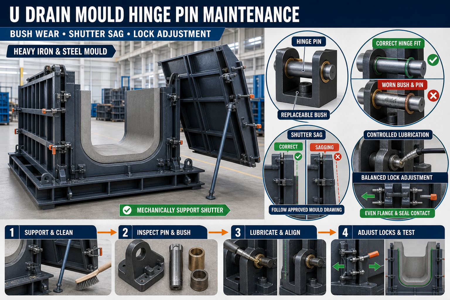
U Drain Mould Hinge Pin Maintenance: Bush Wear, Shutter Sag and Lock Adjustment Guide
U Drain Mould Hinge Pin Maintenance Guide
A folding U drain mould uses hinged side shutters to simplify concrete casting and demoulding. These heavy iron shutters repeatedly open and close during production, placing continuous load on the hinge pins, bushes, brackets and locking points.
Over time, insufficient lubrication, concrete contamination, misalignment or normal wear may increase the clearance between the hinge pin and bush. The shutter can then sag, bind during movement or fail to close uniformly.
This guide explains U drain mould hinge pin maintenance, including bush-wear inspection, shutter-sag diagnosis, lubrication, pin replacement and lock adjustment.
What Is a U Drain Mould Hinge System?
The hinge system connects the folding shutter to the mould base and guides its opening and closing movement.
A typical hinge assembly may include:
• Heavy iron hinge brackets • Hinge pin • Replaceable bush • Pin-retaining plate • Washer or spacer • Grease point • Welded mounting lugs • Side shutter • Base frame • Mechanical stop • Locking clamp or wedge
The exact configuration should follow the approved U drain mould drawing.
Why Hinge Maintenance Is Important
The hinge system controls the movement and final position of the shutter. Excessive wear can affect both mould operation and concrete dimensions.
Regular maintenance helps:
• Maintain smooth shutter movement • Reduce side-shutter sag • Keep flange joints aligned • Improve lock engagement • Maintain gasket compression • Reduce slurry leakage • Prevent pin seizure • Protect hinge brackets • Improve demoulding control • Maintain U drain dimensional consistency
Hinge problems should be repaired before they damage the mould frame or finished concrete products.
Common Signs of Hinge and Bush Wear
Operators may notice:
• Shutter drops after unlocking • Top and bottom flange gaps are unequal • Locking clamps are difficult to engage • Shutter rubs against the mould base • Hinge produces grinding or knocking sounds • Shutter movement becomes jerky • Hinge pin rotates inside the wrong component • Grease contains metal particles • Bush edges appear damaged • Pin-retaining parts repeatedly loosen • Slurry leaks near one end • Concrete dimensions vary between casting cycles
A visibly sagging shutter should not be forced closed using the locks.
Safety Before Hinge Inspection
A U drain mould shutter is heavy and can move suddenly when the locking system or hinge pin is released.
Before maintenance:
1. Stop production. 2. Remove the precast component and loose materials. 3. Isolate hydraulic or powered systems where fitted. 4. Apply the plant’s lockout and tagout procedure. 5. Position the shutter safely. 6. Support it using approved mechanical supports. 7. Confirm that the support can carry the shutter load. 8. Keep personnel away from pinch points. 9. Use suitable personal protective equipment. 10. Allow only trained personnel to remove hinge pins.
Never rely only on a hydraulic cylinder, lifting chain or hinge pin to hold a shutter during maintenance.
Clean the Hinge Assembly
Concrete slurry and dust can hide wear and prevent proper inspection.
Clean:
• Hinge-pin ends • Bush faces • Grease points • Retaining plates • Mounting lugs • Washers and spacers • Welded brackets • Mechanical stops • Nearby locking points • Shutter-contact surfaces
Avoid uncontrolled hammering that could deform the hinge brackets.
Initial Visual Inspection
Inspect the complete hinge system before dismantling it.
Look for:
• Bent hinge pins • Cracked brackets • Broken welds • Missing retainers • Loose bolts • Uneven bush position • Rust • Hardened grease • Concrete contamination • Elongated holes • Shutter misalignment • Contact between moving and stationary parts
Record the location of each problem.
Check Shutter Sag
Shutter sag occurs when the unsupported end of the shutter drops below its intended position.
A basic inspection may include:
1. Place the mould on a level base. 2. Support the shutter safely. 3. Establish a fixed reference point. 4. Check the shutter position when closed. 5. Open it partially using the approved method. 6. Observe vertical movement at the free end. 7. Compare the top and bottom flange positions. 8. Record the result. 9. Compare it with the approved maintenance requirement.
Do not estimate sag only by looking at the locking handle.
Possible Causes of Shutter Sag
Shutter sag can result from:
• Worn hinge bushes • Worn or bent hinge pins • Elongated hinge holes • Cracked mounting brackets • Poor hinge alignment • Base-frame distortion • Loose hinge fasteners • Missing washers or spacers • Shutter-frame bending • Incorrect previous repair • Excessive force applied through the locks
Inspect the complete system rather than replacing only one visible component.
Inspect the Hinge Pin
After safely supporting the shutter, remove the hinge pin according to the approved procedure.
Check the pin for:
• Diameter wear • Flat spots • Grooves • Scoring • Pitting • Rust • Bending • Cracks • Damaged retaining grooves • Hammer damage • Uneven polishing
A pin showing significant deformation or surface damage should not be returned to service without approval.
Check Pin Straightness
Roll the cleaned pin on an approved flat surface or inspect it using a suitable measuring setup.
A bent pin may:
• Bind during movement • Wear the bush unevenly • Misalign the shutter • Damage mounting lugs • Make installation difficult • Increase operating force
Do not straighten a critical pin using uncontrolled heating or hammering.
Inspect the Hinge Bush
The bush provides a replaceable wear surface between the hinge pin and bracket.
Check it for:
• Uneven internal wear • Oval shape • Cracks • Splitting • Loose fit in the housing • Rotation inside the bracket • Scoring • Damaged edges • Corrosion • Blocked grease passages • Metal particles
Bush wear should be measured using suitable tools and compared with the approved maintenance limit.
Signs of an Oval Bush
An oval or unevenly worn bush may cause:
• Vertical shutter movement • Knocking during opening • Uneven flange contact • Rapid pin wear • Misaligned locks • Irregular grease distribution
Replacing the hinge pin without replacing a badly worn bush may not remove the shutter sag.
Check the Hinge Brackets
Hinge brackets transfer shutter loads into the mould frame.
Inspect:
• Bracket alignment • Welded connections • Cracks • Bent plates • Elongated holes • Base-frame connection • Corrosion • Previous repairs • Contact with the shutter • Distance between paired brackets
A cracked bracket requires qualified assessment and repair.
Check Hinge Alignment
All hinges on one shutter should operate on the intended common axis.
Misaligned hinges can cause:
• Pin binding • Difficult shutter movement • Accelerated bush wear • Bracket cracking • Lock misalignment • Shutter twisting
Use a straight reference bar, alignment fixture, laser or another approved method to check the hinge axis.
Do not force a pin through misaligned hinge brackets.
Lubricating Hinge Pins and Bushes
Correct lubrication reduces friction and helps prevent pin seizure.
Use only the lubricant recommended for the hinge system and operating environment.
Good lubrication practices include:
• Clean the grease point before application • Remove hardened contamination • Confirm that the grease passage is open • Apply the recommended lubricant • Move the shutter through a controlled cycle • Wipe away excessive grease • Keep concrete slurry away from the joint • Record lubrication activity
Do not apply new grease over heavy concrete contamination without cleaning the hinge first.
Problems Caused by Insufficient Lubrication
Insufficient lubrication may lead to:
• Grinding noise • Jerky shutter movement • Pin scoring • Bush overheating • Rust • Rapid wear • Hinge seizure • Increased operating force
Frequent dry operation can damage both the pin and bush.
Problems Caused by Excessive Lubrication
Excessive grease can:
• Attract cement dust • Form an abrasive paste • Hide cracks • Contaminate casting surfaces • Spread onto the factory floor • Make inspection difficult
Apply lubricant according to the approved maintenance requirement.
Preventing Slurry Entry
Cement slurry can enter the hinge clearance and harden around the pin.
To reduce contamination:
• Maintain joint seals • Clean hinges after every casting cycle • Repair leakage near hinge locations • Protect grease points • Remove slurry before it hardens • Keep flange surfaces aligned • Adjust locks correctly • Replace damaged sealing strips
Repeated slurry buildup may indicate a mould-joint or lock-alignment problem.
Hinge Pin and Bush Replacement
Replace components when wear exceeds the approved limit or when damage affects safe operation.
A controlled replacement process includes:
1. Identify the correct replacement components. 2. Support the shutter mechanically. 3. Remove retaining parts. 4. Extract the pin without damaging brackets. 5. Remove the worn bush using the approved method. 6. Clean and inspect the housing. 7. Check bracket alignment. 8. Install the approved replacement bush. 9. Lubricate the new components. 10. Install the hinge pin. 11. Secure the retaining arrangement. 12. Move the shutter slowly. 13. Recheck alignment and sag.
Pins and bushes should match the approved material and dimensions.
Do Not Modify the Pin Without Approval
Using an undersized pin, welding directly onto the pin or enlarging the hinge hole can create further misalignment.
Avoid:
• Random replacement rods • Unapproved material grades • Loose-fitting pins • Excessive welding • Uncontrolled reaming • Improvised retainers • Mixing mismatched pin and bush sizes
Repairs should restore the designed hinge geometry.
Check Washers and Spacers
Washers and spacers help control sideways movement and maintain hinge position.
Inspect them for:
• Wear • Missing components • Incorrect thickness • Cracks • Deformation • Loose fit • Uneven positioning • Slurry contamination
Missing spacers may allow the shutter to move sideways and affect flange alignment.
Lock Adjustment After Hinge Repair
Locks should be adjusted only after the hinge pin, bush and shutter alignment are correct.
The locks should:
• Pull the shutter into its designed closed position • Apply balanced closing force • Maintain joint contact • Compress the gasket evenly • Remain easy to engage and release • Avoid bending the shutter • Stay secure during concrete casting and vibration
Locks must not be used to lift a sagging shutter into position.
Check Locking Components
Inspect:
• Locking clamps • Wedges • Pins • Bolts • Threads • Lock brackets • Handles • Contact pads • Retaining parts • Welded supports
Replace worn or damaged components before final adjustment.
Balanced Lock Adjustment
A practical lock-adjustment sequence is:
1. Close the shutter slowly. 2. Confirm hinge alignment. 3. Check the bottom flange contact. 4. Check the top flange contact. 5. Engage all locks lightly. 6. Adjust opposing locks gradually. 7. Check gasket compression. 8. Recheck shutter straightness. 9. Complete final tightening. 10. Operate the shutter through a controlled test cycle.
Do not fully tighten one lock while others remain disengaged.
Avoid Over-Tightening Locks
Excessive lock pressure may:
• Bend the shutter • Damage the gasket • Increase hinge loading • Distort the flange • Make release difficult • Shorten lock life • Pull the mould out of alignment
Use the approved lock setting and tightening method.
Inspect the Flange Joint
After hinge and lock adjustment, check the complete flange.
Inspect for:
• Uniform contact • Top-to-bottom alignment • Gaps • Concrete deposits • Damaged edges • Worn gasket • Uneven compression • Local steps • Previous impact damage
A clean, aligned flange supports better slurry control.
Check the Gasket or Seal
Where the mould uses sealing material, inspect it for:
• Cuts • Cracks • Hardening • Flattening • Missing sections • Poor seating • Concrete contamination • Oil damage • Uneven compression
Replace damaged sealing material with an approved compatible product.
Controlled Shutter Movement Test
After completing maintenance, operate the empty mould through a controlled cycle.
Observe:
• Initial shutter movement • Movement through the full approved range • Noise • Binding • Hinge-pin rotation • Shutter sag • Contact with the base • Mechanical-stop engagement • Lock alignment • Final flange closure
Stop if the shutter moves suddenly or produces abnormal noise.
Pre-Casting Inspection
Before the next concrete pour, verify:
• Hinge pins are retained • Bushes are correctly seated • Grease points are secure • Shutter moves smoothly • Mechanical stops work correctly • Locks engage evenly • Flanges are clean • Seals are undamaged • Mould dimensions match the approved drawing • No tools remain inside the mould
Record the inspection according to the production quality procedure.
Common Problems and Corrective Actions
Shutter Drops After Unlocking
Check bush clearance, hinge-pin wear, missing spacers, cracked brackets and shutter-frame distortion.
Hinge Pin Is Difficult to Remove
Possible causes include rust, slurry buildup, pin bending, bracket misalignment or load remaining on the pin.
New Bush Wears Quickly
Inspect pin condition, hinge-axis alignment, lubrication and bracket distortion.
Shutter Binds During Opening
Check hinge alignment, pin straightness, mechanical stops, concrete buildup and shutter contact.
Lock Is Difficult to Engage
Do not force it. Check shutter sag, hinge wear, flange contamination and lock-bracket alignment.
Slurry Leaks Near the Hinge End
Inspect flange contact, gasket condition, hinge sag and lock adjustment.
Repeated Pin-Retainer Failure
Check pin movement, retainer design, hinge alignment and excessive shutter vibration.
Preventive Maintenance Checklist
After Every Casting Cycle
• Remove slurry from hinges • Clean locking points • Inspect visible pin movement • Check shutter closure • Observe flange leakage • Lubricate where required
Scheduled Checks
• Measure pin and bush wear • Check shutter sag • Inspect hinge-axis alignment • Examine brackets and welds • Check washers and spacers • Inspect grease passages • Adjust locks • Check seals • Record replaced components • Test shutter movement
When Should Production Be Stopped?
Stop using the U drain mould if you find:
• Broken hinge pins • Severely worn bushes • Cracked hinge brackets • Failed retaining components • Excessive shutter sag • Shutter binding • Locks that cannot engage • Major slurry leakage • Distorted iron shutters • Unsafe shutter movement
Production should resume only after repair, alignment verification and a controlled movement test.
Conclusion
Regular U drain mould hinge pin maintenance is essential for smooth shutter movement, correct flange alignment and reliable locking.
Worn bushes, bent pins, cracked brackets and missing spacers can cause shutter sag and uneven seal compression. Locks should only be adjusted after correcting the hinge geometry because they are not designed to compensate for a damaged hinge system.
Paras Steel Industries manufactures heavy-duty iron and structural-steel U drain moulds according to customer requirements and approved drawings. Planned hinge inspection, proper lubrication and balanced lock adjustment can support safer operation, cleaner concrete products and consistent production.