
Precast Mould Guide
U Drain Mould Folding Mechanism: Inner Core Removal, Locking and Demoulding Guide
A folding U drain mould simplifies inner-core removal and helps protect the freshly cast concrete during demoulding. This guide explains the folding mechanism, locking arrangement, alignment checks, operating sequence and maintenance requirements of a heavy-duty iron and steel U drain mould.
By Paras Steel Industries ·
U Drain Mould Folding Mechanism: Inner Core Removal, Locking and Demoulding Guide
U Drain Mould Folding Mechanism: Inner Core Removal, Locking and Demoulding Guide
Precast U drains are widely used for stormwater drainage, industrial drainage, highways, residential developments and infrastructure projects. Their U-shaped profile makes mould opening and inner-core removal an important part of the manufacturing process.
If the inner core is pulled out without sufficient clearance, it can damage the concrete edges or place unnecessary stress on the mould. A properly designed folding mechanism reduces this problem by allowing the inner core or shutter sections to move inward before the finished drain is removed.
Paras Steel Industries manufactures precast moulds using iron and heavy-duty steel components. Mould dimensions, plate thickness, folding arrangements and operating systems can be customized according to the required U drain drawing and production capacity.
What Is a Folding U Drain Mould?
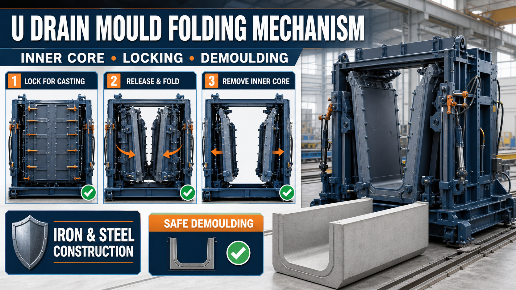
A folding U drain mould is an iron and steel mould equipped with an adjustable or collapsible inner-core system. The inner shutters move or fold inward after the concrete has gained sufficient strength.
This movement creates clearance between the concrete surface and the inner core. The core can then be removed with less risk of damaging the U drain’s walls and edges.
Depending on the mould size and production requirements, the folding system may be operated through:
• Manual screw mechanisms • Mechanical linkages • Hinged shutter arrangements • Lever-operated systems • Hydraulic cylinders • A combination of mechanical and hydraulic components
The exact mechanism should be selected according to the product dimensions, mould weight, production target and available handling equipment.
Main Components of a Folding U Drain Mould
A heavy-duty U drain mould may contain:
• Iron or steel mould base • External side shutters • Folding inner-core shutters • Hinges and pivot points • Mechanical or hydraulic operating mechanism • Locking pins, clamps or wedge locks • End plates • Alignment rods • Reinforcing angles and channels • Lifting and handling points • Mould-supporting frame • Joint-sealing arrangements
Every component must remain properly aligned so the finished U drain maintains the required dimensions and shape.
How Does the Folding Mechanism Work?
Before casting, the inner-core shutters are moved into their correct production position. The shutters are aligned and secured with the designed locking system.
After the concrete is poured, vibrated, finished and cured sufficiently, the locking components are released. The folding mechanism then moves the inner shutters slightly inward.
This inward movement separates the steel surface from the concrete and creates the clearance needed for demoulding.
A typical operating sequence is:
1. Clean the mould and inspect all moving components. 2. Move the folding inner core into the casting position. 3. Check the internal dimensions and alignment. 4. Secure all pins, clamps and locking points. 5. Apply a suitable mould-release agent. 6. Place the reinforcement cage with the specified cover. 7. Pour and vibrate the concrete correctly. 8. Allow the concrete to gain sufficient demoulding strength. 9. Remove the end plates where required. 10. Release the inner-core locking system. 11. Fold or retract the inner shutters gradually. 12. Remove the core or lift the finished U drain safely. 13. Clean and inspect the mould before the next cycle.
Operators should follow the mould manufacturer’s approved operating procedure.
Purpose of the Folding Inner Core
The inner core creates the internal U-shaped profile of the drain. A fixed core may be difficult to remove because the concrete surrounds its side surfaces.
A folding inner core reduces its effective width during demoulding. This provides several potential benefits:
• Easier separation from the concrete • Reduced risk of edge damage • Lower demoulding force • Faster production cycles • Reduced dependence on hammering • Better protection of the mould surface • More consistent product dimensions • Easier handling of larger U drain sections
These benefits depend on correct mould operation and sufficient concrete strength at the time of demoulding.
Importance of the Locking System
The locking mechanism keeps the folding core in its exact casting position while concrete is being poured and vibrated.
If a locking point is loose, the inner shutter may move under concrete pressure. This can change the wall thickness, internal dimensions or alignment of the finished drain.
Before every casting cycle, inspect:
• Locking pins • Wedge locks • Clamps and bolts • Hydraulic locking pressure • Mechanical linkages • Hinges and pivot points • Shutter contact surfaces • End-plate connections
All locking points should be engaged completely and tightened uniformly.
Inner-Core Alignment Checks
Correct inner-core alignment is essential for producing uniform U drains.
Check the following before casting:
Internal Width
Measure the internal width at several points along the mould. The measurement should match the approved product drawing.
Wall Thickness
Verify the distance between the inner core and external shutters. Unequal spacing can produce inconsistent wall thickness.
Vertical Alignment
Check that the inner core remains vertical and does not lean toward either side.
Centreline Position
The inner core should remain centred within the external mould unless the approved product design specifies otherwise.
End Alignment
Inspect the inner core’s position against both end plates. Poor end alignment can cause dimensional variation or slurry leakage.
Locking Position
Confirm that every lock is fully closed after completing the alignment checks.
Concrete Pressure and Mould Stiffness
Fresh concrete applies pressure to the inner and outer mould shutters. Vibration can further increase movement if the frame or locking points are insufficiently reinforced.
The mould should use suitable iron or steel plate thickness, structural angles, channels and stiffeners according to its dimensions and expected concrete pressure.
Plate thickness should not be selected using one general value for every mould. Larger and deeper U drain moulds may require different structural designs than smaller units.
Manual vs Hydraulic Folding System
Manual Folding Mechanism
A manual system may use screw arrangements, levers, hinges or mechanical linkages.
Possible benefits include:
• Simpler construction • Lower initial investment • Easier maintenance • Suitability for moderate production
Manual operation may require more time and labour, particularly for large or heavy inner cores.
Hydraulic Folding Mechanism
A hydraulic system uses cylinders to retract or fold the inner shutters.
Possible benefits include:
• Faster mould operation • Reduced manual effort • Better suitability for heavy shutters • More controlled movement • Improved productivity in suitable plants
Hydraulic systems require regular inspection of cylinders, hoses, seals, fittings and hydraulic pressure. Operators must also be trained in safe hydraulic operation.
When Should a U Drain Be Demoulded?
Demoulding should begin only after the concrete has gained sufficient strength to support its weight and resist handling forces.
The required time depends on:
• Concrete mix design • Cement type • Water-cement ratio • Ambient temperature • Product dimensions • Reinforcement arrangement • Curing method • Use of approved admixtures • Required demoulding strength
A fixed demoulding time should not be assumed for every product or weather condition. The precast manufacturer should establish the required demoulding strength through an approved mix design and quality-control procedure.
Safe Demoulding Process
Before demoulding, confirm that the concrete has achieved the required strength and the handling equipment is suitable for the product weight.
Follow these precautions:
• Clear workers from potential movement zones. • Remove all locks in the correct sequence. • Retract the inner shutters slowly and evenly. • Stop immediately if the core becomes jammed. • Do not apply excessive hammering to the mould. • Use approved lifting points and certified equipment. • Avoid pulling the product from only one side. • Support the finished drain during handling. • Inspect the concrete edges after removal.
Never stand below a suspended precast product or place hands between moving mould sections.
Common Demoulding Problems
Inner Core Does Not Fold Properly
Possible causes include hardened concrete in the joints, damaged hinges, bent linkages, insufficient lubrication or uneven hydraulic movement.
Concrete Sticks to the Mould
This can result from inadequate cleaning, incorrect release-agent application, a damaged mould surface or premature demoulding.
U Drain Edges Break
Possible causes include low concrete strength, sudden shutter movement, insufficient clearance or improper lifting.
Unequal Wall Thickness
This may be caused by poor core alignment, loose locks, shutter movement or incorrect reinforcement-cage positioning.
Cement Slurry Leakage
Leakage can occur through worn joints, loose end plates, damaged seals or incorrectly closed shutters.
Maintenance of the Folding Mechanism
Regular maintenance helps preserve dimensional accuracy and reliable movement.
After every production cycle:
• Remove concrete residue from shutter joints. • Clean the hinges and folding sections. • Inspect locking pins and clamps. • Check mechanical linkages for bending. • Lubricate approved moving components. • Inspect hydraulic hoses and cylinders where installed. • Check shutters for distortion. • Repair slurry-leakage points. • Confirm that the core returns to its correct casting position.
Replace worn pins, bushes, seals and locking components before they affect product quality or operator safety.
Factors to Check Before Buying
Before ordering a folding U drain mould, provide the manufacturer with:
• Complete U drain drawing • Internal and external dimensions • Product length • Wall and base thickness • Reinforcement details • Required number of cavities • Expected daily production • Manual or hydraulic operating preference • Concrete-filling method • Vibration arrangement • Demoulding method • Available crane or handling equipment • Required dimensional tolerance • Factory space and layout details
The buyer should also discuss iron or steel plate thickness, structural stiffeners, inner-core clearance, hinge design, locking arrangements and future size requirements.
Conclusion
A well-designed U drain mould folding mechanism makes inner-core removal easier and helps protect the finished concrete during demoulding.
Correct alignment, complete locking, controlled shutter movement and sufficient concrete strength are essential for consistent production. Regular cleaning and maintenance also prevent the folding mechanism from becoming jammed or misaligned.
Paras Steel Industries manufactures iron and heavy-duty steel precast moulds according to customer drawings, required dimensions and production targets. Complete technical details should be shared before mould design and manufacturing begin.