
Precast Production Guide
Reinforcement Cage for Precast Wall Panels and Poles: Cover, Spacing and Placement Guide
Correct reinforcement cage placement is essential for the strength, durability and dimensional accuracy of precast wall panels and poles. This guide explains concrete cover, bar spacing, cage support and pre-pour inspection.
By Paras Steel Industries ·
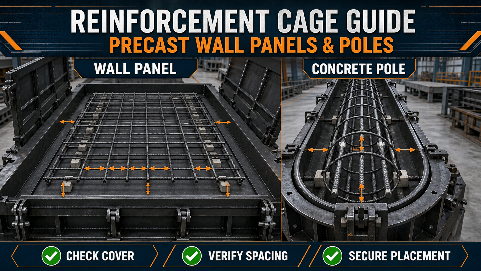
Reinforcement Cage for Precast Wall Panels and Poles: Cover, Spacing and Placement Guide
Reinforcement Cage for Precast Wall Panels and Poles: Cover, Spacing and Placement Guide
The reinforcement cage is one of the most important components inside a precast concrete wall panel or pole. It helps the product resist structural loads, control cracking and remain stable during lifting, transportation and installation.
A correctly fabricated reinforcement cage can still cause problems if it is positioned incorrectly inside the heavy-duty iron precast mould. Insufficient concrete cover, irregular bar spacing, cage movement and incorrect lifting-anchor positions can reduce product quality and durability.
The reinforcement cage must therefore be manufactured and installed according to the approved structural drawing, bar-bending schedule and project specification.
What Is a Reinforcement Cage?
A reinforcement cage is an arrangement of steel bars, welded wire mesh, stirrups, links and other reinforcement components assembled before concrete casting.
Depending on the precast product, the cage may include:
• Main longitudinal bars • Horizontal distribution bars • Vertical distribution bars • Stirrups • Links or ties • Welded wire mesh • Additional corner reinforcement • Opening reinforcement • Lifting-point reinforcement • Connection reinforcement • Starter bars • Embedded plates • Couplers • Anchor-zone reinforcement
The reinforcement arrangement should not be changed without approval from the responsible structural engineer.
Why Correct Cage Placement Is Important
A reinforcement cage must remain in its specified position throughout concrete pouring and vibration.
Correct placement helps to:
• Maintain the required concrete cover • Achieve the intended structural capacity • Control cracking • Protect reinforcement from corrosion • Maintain product dimensions • Strengthen lifting and connection areas • Prevent exposed reinforcement • Improve concrete compaction • Avoid interference with inserts • Support safe lifting and installation • Produce consistent precast products
An incorrectly positioned cage may result in a product that does not match the approved design.
What Is Concrete Cover?
Concrete cover is the distance between the outer surface of the reinforcement and the nearest finished concrete surface.
The required cover protects the reinforcement from:
• Moisture • Corrosion • Fire exposure • Chemicals • Weather conditions • Physical damage
Concrete cover also helps transfer forces between the concrete and reinforcement.
The required cover depends on:
• Product type • Exposure conditions • Reinforcement type • Concrete grade • Fire-resistance requirement • Structural design • Manufacturing tolerance • Applicable standard • Project specification
No universal cover value should be applied to every precast product. Always follow the approved structural drawing.
How to Maintain Concrete Cover
Suitable cover blocks, spacers, chairs and supports are used to maintain the required distance between the reinforcement and iron mould surface.
A good cover-control system should:
• Maintain the specified cover • Carry the weight of the reinforcement cage • Resist movement during concrete pouring • Remain stable during vibration • Avoid damaging the mould surface • Avoid creating unacceptable marks • Be compatible with the finished product • Not reduce concrete durability
The number and spacing of supports should be sufficient to prevent cage sagging or movement.
Common Cover Problems
Insufficient Cover
If reinforcement is too close to the concrete surface, it may become visible or remain inadequately protected from corrosion and fire.
Excessive Cover
Excessive cover can also be a problem because reinforcement may move away from its intended structural position.
Unequal Cover
The cage may be correctly positioned at one end but displaced at another. Cover should therefore be checked at multiple locations.
Broken Cover Blocks
Weak or damaged cover blocks may break during concrete pouring and vibration, allowing the cage to move.
Incorrect Spacer Size
Using the wrong spacer size changes the reinforcement position and finished concrete cover.
What Is Reinforcement Bar Spacing?
Bar spacing is the distance between adjacent reinforcement bars.
Correct spacing allows the cage to perform according to the structural design while leaving sufficient space for concrete to flow around the reinforcement.
Bar spacing should comply with the approved drawing and should allow:
• Proper concrete placement • Aggregate movement • Effective vibration • Full reinforcement encasement • Installation of inserts • Correct concrete cover • Dimensional accuracy
Bars placed too close together can obstruct concrete flow and create honeycombing. Bars positioned too far apart may not provide the required structural performance.
How to Check Bar Spacing
Bar spacing should be checked before the cage is installed and again after it is positioned inside the mould.
The inspection may include:
• Centre-to-centre distance • Clear distance between bars • Number of bars • Bar diameter • Stirrups or link spacing • Mesh size • Lap locations • Additional reinforcement zones • Opening reinforcement • Anchor-zone reinforcement
Use a measuring tape, steel rule, gauge or approved inspection template.
Why Cage Dimensions Must Match the Mould
The reinforcement cage must fit inside the heavy-duty iron mould while maintaining the specified concrete cover on every relevant side.
If the cage is too wide, long or deep, it may:
• Touch the mould surface • Reduce concrete cover • Prevent shutter closure • Interfere with inserts • Cause reinforcement exposure • Damage gaskets or mould joints
If the cage is too small or incorrectly positioned, reinforcement may not remain in the intended structural location.
Before installation, compare the cage dimensions with:
• Internal mould dimensions • Required concrete cover • Product thickness • Opening locations • Insert positions • Lifting-anchor locations • Connection details
Reinforcement Cage for Precast Wall Panels
Wall panel reinforcement usually consists of a mesh or grid arrangement. Structural panels may contain one or more reinforcement layers according to the approved design.
Important wall-panel cage checks include:
• Panel length and width • Cage length and width • Main-bar direction • Horizontal bar spacing • Vertical bar spacing • Concrete cover • Distance between reinforcement layers • Opening reinforcement • Edge reinforcement • Lifting-anchor reinforcement • Connection reinforcement • Insert clearance • Cage flatness
Large cages should be lifted from suitable points to prevent bending before installation.
The cage must remain flat and correctly supported inside the iron wall-panel mould.
Reinforcement Cage for Precast Concrete Poles
Pole reinforcement may include longitudinal bars held in position by spiral reinforcement, rings, links or stirrups.
Important pole-cage checks include:
• Cage length • Cage diameter or profile • Number of longitudinal bars • Longitudinal-bar spacing • Ring, spiral or stirrup spacing • Concrete cover • Cage straightness • End reinforcement • Lifting-point reinforcement • Connection details • Required taper • Alignment with the pole mould
A bent or twisted pole cage can reduce cover and create dimensional variation along the product.
Suitable spacers should hold the cage centrally inside the heavy-duty iron pole mould.
How to Check Cage Straightness
Straightness is particularly important for long precast poles and panels.
To check cage straightness:
1. Place the cage on a level inspection area. 2. Use a string line, straightedge or suitable jig. 3. Check the entire cage length. 4. Identify bent longitudinal bars. 5. Check the alignment of stirrups or links. 6. Correct the cage before placing it in the mould.
Do not use the mould locks to force an oversized or bent reinforcement cage into position.
How to Position the Cage Inside an Iron Mould
A general placement process may include:
1. Clean the heavy-duty iron mould. 2. Check mould dimensions and alignment. 3. Apply the mould release agent correctly. 4. Mark the cage and insert reference positions. 5. Inspect the reinforcement cage. 6. Install the required cover blocks and spacers. 7. Lift the cage from approved handling points. 8. Lower it gradually into the mould. 9. Check cover on all sides. 10. Verify cage alignment. 11. Install lifting anchors and embedded components. 12. Secure the cage against movement. 13. Close the mould shutters carefully. 14. Check cover and dimensions again. 15. Complete the pre-pour inspection.
The release agent should not contaminate the reinforcement because contamination can affect the bond between concrete and steel.
How to Prevent Cage Movement During Casting
Concrete flow and vibration can move an inadequately secured cage.
Cage movement can be controlled through:
• Correctly positioned cover blocks • Suitable side spacers • Strong supporting chairs • Approved temporary fixing points • Reinforcement ties • Installation jigs • Insert-support systems • Controlled concrete pouring • Correct vibrator operation
Temporary supports must not create unacceptable voids, surface defects or corrosion paths.
Role of Cover Blocks and Spacers
Cover blocks maintain the required distance between the cage and mould surface.
They should be selected according to:
• Required cover • Cage weight • Product orientation • Concrete finish • Exposure conditions • Vibration method • Approved technical specification
Spacers should be distributed properly. Using only a few supports can allow the cage to sag between them.
Side spacers may be required to prevent the cage from touching vertical mould shutters.
Reinforcement Around Openings
Wall panels may contain window, door, ventilation or service openings.
Openings interrupt the normal reinforcement arrangement and may require additional bars according to the structural drawing.
Before casting, verify:
• Opening dimensions • Opening position • Additional corner bars • Edge reinforcement • Bar anchorage • Concrete cover • Clearance around the block-out • Connection with the main cage
Reinforcement should not be cut at the factory merely to fit around an opening unless the modification has been approved.
Lifting-Anchor Reinforcement
Lifting anchors transfer substantial forces into the concrete during demoulding and handling.
Anchor reinforcement must be installed according to the approved lifting design.
Check:
• Anchor type • Anchor capacity • Anchor position • Embedment depth • Orientation • Additional reinforcement • Distance from product edges • Clearance from main bars • Stability during casting
Lifting anchors should never be moved only because they interfere with another cage component. The conflict should be reviewed before casting.
Embedded Plates and Inserts
Precast products may include plates, sleeves, couplers and connection inserts.
The reinforcement cage must provide sufficient space for these items without violating concrete cover or bar-spacing requirements.
Use suitable templates to maintain:
• Insert position • Centre-to-centre spacing • Projection • Depth • Orientation • Distance from product edges
All inserts should remain secure during concrete pouring and vibration.
Welding vs Tying Reinforcement
Reinforcement cages may be assembled by tying or approved welding, depending on the reinforcement type and project requirements.
Welding should not be carried out on reinforcement unless the material is suitable and the procedure is approved.
Unauthorised welding can affect reinforcement properties and structural performance.
Ties should be strong enough to maintain cage geometry during lifting, placement and vibration.
Common Reinforcement Cage Mistakes
Incorrect Bar Diameter
Using a different bar size changes the reinforcement area and may affect structural performance.
Wrong Bar Spacing
Incorrect spacing may reduce capacity or obstruct concrete flow.
Insufficient Concrete Cover
Bars placed close to the mould surface may become exposed and vulnerable to corrosion.
Excessive Concrete Cover
Reinforcement positioned too far from the intended location may not perform as designed.
Missing Bars
Additional bars around openings, anchors and connections are sometimes overlooked during cage fabrication.
Poor Cage Tying
Loose ties allow bars and stirrups to move during handling and casting.
Cage Touching the Iron Mould
Direct contact between reinforcement and the casting surface results in inadequate cover.
Too Few Spacers
Insufficient supports can cause cage sagging or movement.
Release Agent on Reinforcement
Oil contamination may reduce the bond between concrete and reinforcement.
Unapproved Bar Cutting
Bars should not be cut, bent or repositioned without technical approval.
Incorrect Anchor Position
A lifting anchor installed in the wrong location can create unsafe lifting forces.
Reinforcement Cage Inspection Checklist
Before Placing the Cage:
• Approved drawing available • Bar-bending schedule checked • Correct bar diameter used • Correct number of bars installed • Bar spacing verified • Cage dimensions checked • Ties or welds inspected • Cage straightness confirmed • Surface contamination removed • Required additional bars installed
After Placing the Cage:
• Bottom cover checked • Side cover checked • Top cover checked where applicable • Cage centred correctly • Spacers securely positioned • Cage supported against sagging • Openings correctly reinforced • Lifting anchors verified • Inserts correctly positioned • Shutters close without touching the cage • Cage cannot move during casting • Final inspection recorded
Quality-Control Records
The reinforcement inspection record may include:
• Product identification • Mould number • Drawing number • Reinforcement grade • Bar diameters • Bar spacing • Cage dimensions • Cover requirement • Actual cover measurements • Insert positions • Lifting-anchor details • Inspection date • Corrective action • Inspector approval
Photographic records can also improve production traceability.
How Mould Design Supports Correct Cage Placement
A well-designed heavy-duty iron precast mould helps the production team position reinforcement accurately.
Useful mould features may include:
• Fixed dimensional reference points • Insert-location markings • Removable shutters • Accessible cage-placement areas • Accurate internal dimensions • Strong locking arrangements • Suitable opening sequence • Stable base frame • Support points for approved cage fixtures • Smooth casting surfaces
The mould should provide sufficient working access without losing structural rigidity or dimensional accuracy.
Final Conclusion
Correct reinforcement cage placement is essential for the strength, durability and quality of precast wall panels and poles.
Concrete cover, bar spacing, cage dimensions, straightness, lifting-anchor reinforcement and insert positions must follow the approved structural drawing.
Suitable cover blocks, spacers, chairs and fixing arrangements should prevent cage movement during concrete pouring and vibration.
The cage should be inspected before installation and checked again after the shutters of the heavy-duty iron mould have been closed.
Paras Steel Industries manufactures customised heavy-duty iron precast moulds for wall panels, poles and other precast products. Moulds can be manufactured according to the required product dimensions, reinforcement arrangement, insert locations and production capacity.
For customised mould specifications and pricing, share your precast product drawing, reinforcement details, product dimensions and daily production target with Paras Steel Industries.