
Precast Mould Guide
How to Prevent Bowing in Big Size Wall Panel Moulds: Support Grid, Camber and Flatness Checks
Bowing in a big size wall panel mould can produce curved panels, uneven joints and installation problems. This guide explains how iron support grids, approved camber, level foundations and regular flatness checks help maintain mould accuracy.
By Paras Steel Industries ·
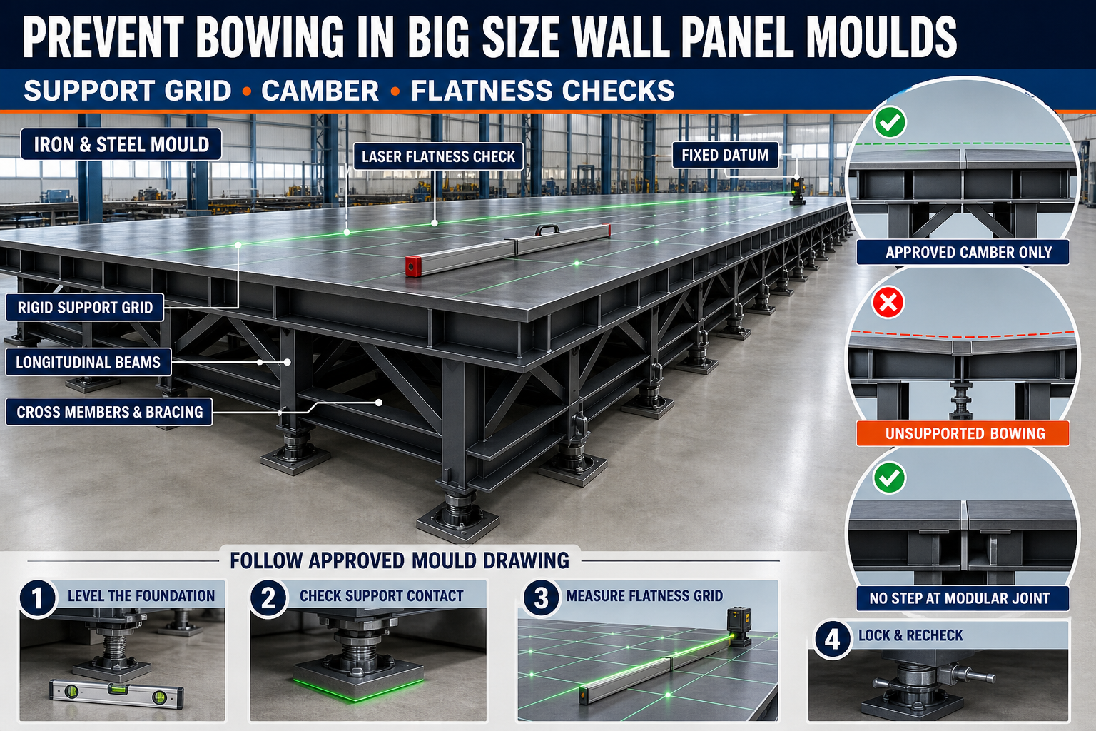
How to Prevent Bowing in Big Size Wall Panel Moulds: Support Grid, Camber and Flatness Checks
How to Prevent Bowing in Big Size Wall Panel Moulds
Big size precast wall panels require long and accurately fabricated moulds. As the mould length and width increase, the risk of bending, twisting and surface distortion also increases.
Fresh concrete pressure, vibration, uneven supports, welding stress and improper handling can cause an iron mould to bow. Even a small mould distortion may affect panel straightness, joint alignment and installation quality.
This guide explains how support-grid design, controlled camber, foundation preparation and flatness checks can help prevent bowing in big size wall panel moulds.
What Is Bowing in a Wall Panel Mould?
Bowing is an unwanted curve or deflection in the mould’s casting surface, side shutter or supporting frame.
It may occur:
• Along the mould length • Across the mould width • At the centre of the casting surface • Near unsupported edges • Around welded joints • Between structural stiffeners • At modular connection points
A bowed mould can transfer its shape directly to the precast concrete panel.
How Bowing Affects Precast Wall Panels
Mould bowing can cause:
• Curved wall panels • Uneven panel thickness • Misaligned panel joints • Installation gaps • Difficulty during stacking • Uneven architectural patterns • Damaged edges during handling • Poor fit between columns and panels • Rejection or rework at the project site
The acceptance limits should follow the approved product drawing and project quality requirements.
Common Causes of Mould Bowing
Insufficient Structural Support
A large casting plate without an adequate supporting grid may bend under its own weight and fresh concrete pressure.
Incorrect Stiffener Spacing
Large unsupported areas between stiffeners can allow local plate deformation.
Uneven Foundation
If the mould base is supported only at a few points, it may twist or sag between those points.
Welding Distortion
Uncontrolled welding heat and an incorrect welding sequence can pull the mould structure out of alignment.
Uneven Concrete Placement
Placing most of the concrete in one area can temporarily create an unbalanced load.
Excessive Vibration
Uncontrolled vibration can loosen supports and increase dynamic stress on the mould.
Improper Handling
Lifting a long mould from unsuitable points may permanently bend its base frame.
Thermal Effects
Uneven heating from sunlight, steam or nearby equipment can temporarily change mould alignment.
Damaged or Loose Locks
Loose side-shutter locks can allow movement during concrete placement and vibration.
Importance of the Support Grid
The support grid is the structural framework fitted beneath or behind the mould’s casting plate. It distributes concrete pressure and helps the plate retain its designed shape.
A typical iron support grid may include:
• Longitudinal structural members • Cross members • Edge frames • Intermediate stiffeners • Diagonal bracing • Support legs • Levelling points • Welded connection plates
The size and spacing of these members should be determined according to the mould dimensions, plate thickness, concrete pressure and approved engineering design.
Support-Grid Functions
A properly designed support grid helps:
• Distribute load across the mould • Reduce local plate bending • Control longitudinal sagging • Maintain casting-surface flatness • Support mould transportation • Keep modular sections aligned • Reduce vibration-related movement • Protect the mould from permanent deformation
Adding more steel without a planned structural arrangement does not automatically produce a better mould. The support grid should transfer loads through a clear and balanced path.
Longitudinal Support Members
Longitudinal members run along the length of the mould. They help control sagging in long wall panel moulds.
During inspection, check:
• Member straightness • Connection with cross members • Weld condition • Support at both ends • Intermediate support points • Signs of local bending • Corrosion or impact damage
Long members must remain continuous or be properly joined according to the mould design.
Cross Members and Stiffeners
Cross members support the casting plate across its width and connect the main longitudinal members.
They help:
• Reduce unsupported plate area • Control local deformation • Maintain panel width • Transfer vibration forces • Support edge shutters • Maintain mould squareness
Missing, bent or poorly welded cross members can create local high or low areas in the casting surface.
Diagonal Bracing
Diagonal bracing helps prevent the base frame from moving out of square. It is particularly useful when a large mould is transported or repeatedly lifted.
Check bracing for:
• Cracked welds • Loose bolts • Bent sections • Corrosion • Poor connection with the main frame • Interference with other components
Bracing should not obstruct normal cleaning, vibration or mould operation.
What Is Camber in a Wall Panel Mould?
Camber is a controlled upward or downward adjustment intentionally introduced into a mould or supporting frame to compensate for predictable deflection.
Camber is different from accidental bowing:
• Camber is planned and measured • Bowing is unintended deformation • Camber follows an approved design • Bowing can change unpredictably
Camber should only be used where specified by the mould designer or approved project drawing.
Do Not Apply Camber by Guesswork
Incorrect camber can produce a permanently curved concrete panel.
Before introducing camber, consider:
• Mould length and width • Casting-plate thickness • Support-grid design • Concrete load • Mould orientation • Production method • Vibration system • Temperature conditions • Expected structural deflection
The required camber value must be determined through engineering calculations or an approved fabrication drawing.
Camber Adjustment Points
Some big size wall panel moulds may include adjustable support or levelling points.
These may be used to:
• Correct minor base variation • Set the approved mould profile • Maintain support contact • Compensate for predictable loading • Restore alignment after relocation
Adjustment points must be locked securely after setting. Operators should recheck the complete mould because changing one support may affect other areas.
Prepare a Level Foundation
A strong mould can still bow if its foundation is uneven.
Before installing the mould:
1. Clean the installation area. 2. Inspect the floor or foundation. 3. Establish a fixed level reference. 4. Mark the mould support locations. 5. Position the mould on all designed support points. 6. Remove gaps beneath the base frame. 7. Adjust levelling points gradually. 8. Recheck the complete mould. 9. Secure the mould where required.
Do not support a long mould only at its corners unless it was specifically designed for that arrangement.
Avoid Uneven Packing
Random pieces of scrap steel, wood or broken concrete should not be used as permanent packing beneath a heavy mould.
Poor packing can:
• Create point loads • Move during vibration • Corrode or deteriorate • Change the mould level • Twist the base frame • Create unsafe working conditions
Use approved levelling plates, supports or adjustment systems.
Checking Casting-Surface Flatness
Flatness checks should be performed before the first casting and at planned intervals.
Useful inspection tools may include:
• Precision straightedge • Feeler gauges • Survey level • Laser level • String line • Dial indicator • Total station for large installations • Approved checking template
The selected method should match the mould size and required accuracy.
Straightedge Flatness Check
A straightedge can help identify local high and low areas.
Basic procedure:
1. Clean the casting surface. 2. Place the straightedge at selected locations. 3. Check along the length. 4. Check across the width. 5. Check diagonally. 6. Observe gaps beneath the straightedge. 7. Record the results. 8. Compare them with the approved tolerance.
Do not perform the check over hardened slurry or loose debris.
Laser or Survey-Level Check
For a big size wall panel mould, a laser or survey-level method can provide a more complete surface profile.
Establish a fixed datum and record readings at planned grid points. Use the same checking locations during future inspections so that changes can be compared.
Do not measure every point from the previous point because accumulated errors may hide the actual mould profile.
Flatness Grid Inspection
Marking a regular inspection grid on the mould frame can make checking more consistent.
The grid should cover:
• All four corners • Centre area • Long edges • Short edges • Modular joints • Support locations • Areas between major stiffeners • Vibration zones
Record high and low points on an inspection sheet.
Check Mould Straightness
Flatness and straightness are related but different.
Flatness checks the complete surface, while straightness checks deviation along a selected line.
Check straightness:
• Along both long edges • Along the mould centreline • Across both ends • At modular flange joints • Along shutter-contact surfaces
Use a fixed reference so that repeated inspections remain comparable.
Check Mould Squareness
A twisted or out-of-square mould can create diagonal dimensional differences.
Inspect squareness by:
• Checking approved diagonal references • Verifying corner positions • Using an engineer’s square where suitable • Checking the base frame • Inspecting modular connections • Confirming shutter alignment
The required measurements must follow the mould drawing.
Control Welding Distortion During Fabrication
Welding creates concentrated heat that can shrink and distort iron components.
To reduce welding distortion:
• Use an approved welding sequence • Balance welds on opposite sides • Use suitable fixtures and clamps • Avoid excessive heat concentration • Use intermittent welding where approved • Allow controlled cooling • Check alignment during fabrication • Complete final inspection after welding
Do not attempt to straighten a mould using uncontrolled heating.
Check Modular Mould Joints
Large wall panel moulds may use modular sections for transportation or length adjustment.
At each joint, inspect:
• Flange alignment • Alignment pins • Bolts • Casting-surface continuity • Slurry seal • Support beneath the joint • Internal steps or gaps • Joint straightness
Every modular section should be measured from a fixed datum during assembly.
Concrete Placement Sequence
Uneven concrete placement can create temporary high loads on one mould area.
For balanced loading:
• Place concrete in a planned sequence • Distribute concrete progressively • Avoid filling only one end first • Monitor the mould during casting • Keep side-shutter locks engaged • Do not exceed the approved filling rate • Stop if abnormal movement is observed
The placement method should match the mould and concrete production plan.
Controlled Vibration
Vibration should compact the concrete without causing uncontrolled mould movement.
During vibration:
• Use the approved vibration system • Check mounting bolts • Keep vibration distribution balanced • Avoid excessive vibration time • Monitor locks and supports • Observe slurry leakage • Stop if the mould moves or produces abnormal noise
Excessive vibration can loosen supports, move reinforcement and increase stress on the mould frame.
Thermal Effects on Large Iron Moulds
A large iron mould can expand or contract when exposed to uneven temperatures.
To reduce thermal variation:
• Avoid leaving one mould side in strong sunlight • Maintain consistent factory conditions where possible • Do not apply uncontrolled heating • Allow the mould to reach a stable temperature before final measurement • Check alignment after steam-curing exposure where applicable • Record unusual environmental conditions
Precision inspections should be performed under reasonably stable conditions.
Correct Mould Lifting and Transportation
A long mould should only be lifted from designed lifting points.
Before lifting:
• Confirm the mould weight • Use approved lifting points • Use suitable lifting beams where required • Keep the lift balanced • Avoid lifting from shutters or locking brackets • Prevent uncontrolled swinging • Place the mould on adequate supports • Recheck alignment after relocation
Lifting from unsuitable points can permanently bend the support frame.
Common Bowing Problems and Corrections
Centre of Mould Is Low
Possible causes include insufficient intermediate support, weak longitudinal members or excessive load concentration.
One Corner Is High
Check the foundation, levelling points, diagonal bracing and base-frame twist.
Casting Plate Has Local Waves
Possible causes include large stiffener spacing, welding distortion, damaged plate or poor connection with the support grid.
Mould Changes Shape During Vibration
Inspect foundation contact, locking points, spring or vibrator mounting, frame stiffness and loose fasteners.
Modular Joint Creates a Step
Check flange cleanliness, alignment pins, joint support, bolt-tightening sequence and slurry-sealing material.
Bowing Returns After Adjustment
The underlying cause may be structural weakness, foundation settlement, thermal movement or improper lifting. Adjustment alone may not provide a permanent solution.
Pre-Casting Flatness Checklist
Before each production cycle, check:
• Foundation condition • Base-frame support • Casting-surface cleanliness • Longitudinal straightness • Crosswise flatness • Diagonal alignment • Modular joints • Side-shutter position • Locking system • Support-grid condition • Levelling-point security • Signs of previous movement
Detailed measurements can be completed according to the plant’s inspection schedule.
Post-Casting Inspection
After demoulding, inspect both the mould and finished wall panel.
Check the mould for:
• Loose supports • Cracked welds • Concrete buildup • Damaged locking points • Local plate deformation • Changed level or camber
Check the panel for:
• Surface straightness • Edge alignment • Thickness consistency • Joint profile • Bowing or twisting • Corner condition • Insert positions
Repeated panel distortion in the same location may indicate a mould or support-grid problem.
Preventive Maintenance
Recommended maintenance practices include:
• Clean the mould after every casting cycle • Inspect supports and stiffeners • Tighten loose bolts • Repair damaged welds through qualified personnel • Protect iron surfaces from corrosion • Check flatness at planned intervals • Record alignment readings • Lubricate hinges and locks • Recheck the mould after relocation • Store unused moulds on adequate supports
Maintenance records help identify gradual changes before they affect production quality.
Conclusion
Preventing bowing in big size wall panel moulds requires a properly designed support grid, stable foundation, controlled welding, balanced concrete placement and regular flatness checks.
Camber should only be introduced when specified in an approved engineering design. Applying it through guesswork can create an incorrect panel profile.
Paras Steel Industries manufactures heavy-duty iron and structural-steel precast moulds according to customer requirements and approved drawings. Correct mould fabrication, installation and inspection help support straight panels, consistent dimensions and reliable production.