
Precast Mould Guide
Precast Window Frame Mould Tapered Core Removal: Pull Direction, Sticking and Corner Protection Guide
A tapered core must be removed in its designed pull direction to avoid binding, concrete chipping and damaged window-frame corners. This guide explains core preparation, controlled extraction and sticking diagnosis.
By Paras Steel Industries ·
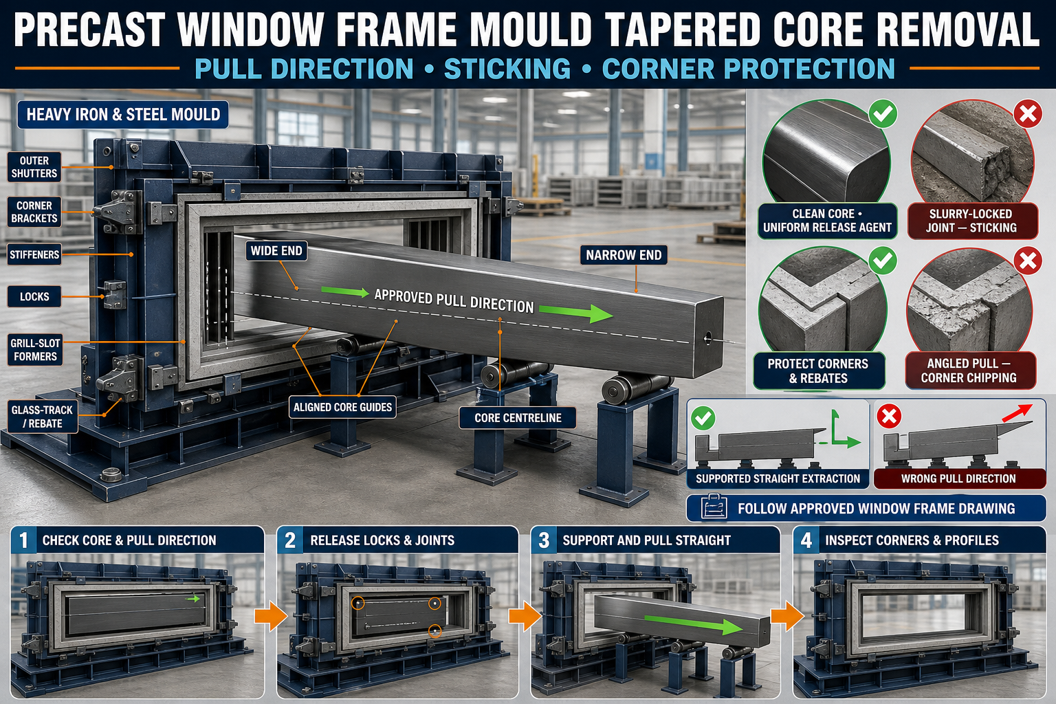
Precast Window Frame Mould Tapered Core Removal: Pull Direction, Sticking and Corner Protection Guide
Precast Window Frame Mould Tapered Core Removal Guide
A precast concrete window frame mould uses internal core components to form the clear window opening, grill-fixing slots, glass tracks, rebates and other approved profiles.
The core must remain rigid and accurately positioned during reinforcement placement, concrete filling and vibration. After the concrete reaches the required stripping condition, the core must be removed without damaging the frame’s narrow corners and edges.
A controlled taper or draft allows the core to release in one designed direction. If operators pull from the wrong side, use excessive force or allow slurry to lock the joints, the core may bind inside the concrete.
This guide explains window frame mould tapered core removal, including pull direction, release preparation, sticking diagnosis and concrete-corner protection.
What Is a Tapered Core?
A tapered core is a removable iron or structural-steel mould component with a controlled draft along its release direction.
It may form:
• Clear window opening • Inner frame faces • Grill-fixing slot • Glass-track profile • Shutter rebate • Corner radius or chamfer • Drainage detail • Custom frame section
The exact profile and taper should follow the approved window-frame drawing.
Purpose of the Taper
A correctly designed taper helps:
• Reduce concrete-to-core binding • Establish one release direction • Protect frame edges • Reduce extraction force • Improve repeated demoulding • Limit core damage • Maintain the approved inner profile • Support a cleaner concrete surface
The taper should not be changed through grinding or guesswork.
Why Correct Pull Direction Matters
The wider and narrower ends of the tapered core establish the intended extraction direction.
Pulling in the wrong direction can:
• Wedge the core into the concrete • Increase contact pressure • Break frame corners • Crack the concrete • Bend core brackets • Damage pulling points • Distort the heavy iron mould • Create an unsafe sudden release
Always identify the approved pull direction before casting and demoulding.
Types of Window Frame Core Systems
Depending on the mould design, the inner core may be:
• One-piece removable core • Multi-piece collapsible core • Sectional corner core • Bolted core assembly • Wedge-released core • Hinged core • Tapered slide-out core • Custom combination system
The removal sequence must match the actual core design.
Safety Before Core Removal
The core may be heavy and can release suddenly.
Before demoulding:
1. Confirm that the concrete has reached the approved stripping condition. 2. Stop nearby vibration equipment. 3. Isolate hydraulic or powered systems. 4. Apply lockout and tagout where required. 5. Position the mould on a stable base. 6. Clear the core-withdrawal path. 7. Inspect the approved pulling equipment. 8. Keep personnel away from the pull line. 9. Support the core during extraction. 10. Wear suitable personal protective equipment.
Never stand directly behind a tensioned pulling device.
Inspect the Heavy Iron Mould
Before casting and again before demoulding, inspect:
• Outer frame • Inner core • Corner joints • Base plate • Structural stiffeners • Core guides • Pulling points • Alignment pins • Locks • Wedges • Mechanical stops • Sealing surfaces
A distorted outer mould can place unintended pressure on the core.
Identify the Core Orientation
Mark or identify:
• Top • Bottom • Left • Right • Wide end • Narrow end • Pull direction • Casting face • Core identification • Mould cavity number
Use markings that cannot transfer onto the finished concrete.
Pull-Direction Marking
A permanent arrow or approved tag on the core can help prevent incorrect removal.
The mark should remain:
• Visible after casting • Clear of the concrete surface • Resistant to cleaning • Associated with the correct core • Included in the setup checklist
Do not depend only on operator memory.
Inspect the Core Before Casting
Check the core for:
• Straightness • Twisting • Damaged taper • Dents • Concrete buildup • Rust • Rough surfaces • Cracked welds • Bent extraction brackets • Enlarged bolt holes • Damaged guide points • Previous unapproved repairs
A damaged core should be repaired and verified before use.
Check Taper Continuity
The taper should remain consistent along the intended release path.
Inspect:
• All core faces • Both ends • Corner transitions • Rebate details • Grill or glass-track profiles • Sectional joints • Previous repair locations
Use an approved profile gauge or template.
Do Not Modify the Taper Without Approval
Uncontrolled grinding can:
• Change the frame opening • Make one side uneven • Produce an incorrect rebate • Create visible concrete steps • Reduce core strength • Increase future sticking • Change the pull direction
Any repair should restore the approved profile.
Clean the Core Surface
Remove:
• Hardened concrete • Cement slurry • Rust • Old release-agent buildup • Dirt • Burrs • Damaged sealant • Material inside profile grooves
Pay special attention to corners and narrow tracks.
Inspect Core Guides and Slides
Core guides maintain alignment during installation and withdrawal.
Check:
• Guide straightness • Wear • Slurry buildup • Alignment • Fasteners • Welded brackets • Corrosion • Clearance • Mechanical stops • Contact through the full travel path
Misaligned guides can force a straight core sideways.
Dry-Run the Empty Core
Before reinforcement and concrete placement, complete a controlled empty movement test.
A suitable process includes:
1. Clean the mould and core. 2. Place the core in its guides. 3. Engage locating points. 4. Lock the core. 5. Confirm its position. 6. Release the locks. 7. Withdraw it in the marked direction. 8. Check for binding. 9. Reinstall it. 10. Record any abnormal resistance.
Complete this test before the first casting after repair or adjustment.
Check Full Core Seating
During setup, verify:
• Core reaches its approved stop • All locating pins engage • Sectional joints close • Core centreline matches the mould • Corner gaps are controlled • Profile inserts align • Core cannot lift or rotate • Pulling points remain accessible
A partially seated core may create dimensional defects.
Apply Mould-Release Agent
A suitable release agent helps reduce bonding between concrete and the iron core.
The release agent should be:
• Compatible with precast concrete • Suitable for iron or steel • Applied to a clean and dry core • Spread in a thin uniform layer • Applied into detailed profiles • Prevented from pooling • Kept away from reinforcement-bond areas • Used according to its manufacturer’s instructions
Do not use diesel or used engine oil.
Insufficient Release Agent
Too little release agent may cause:
• Concrete bonding • Increased pulling force • Rough inner surfaces • Corner chipping • Core scoring • Difficult cleaning
Excessive Release Agent
Too much release agent may cause:
• Surface staining • Pinholes • Pooled material in tracks • Loss of sharp profile details • Concrete contamination • Uneven finish
Apply a controlled film.
Core Joint Sealing
Slurry entering core joints can harden and prevent movement.
Inspect:
• Sectional core joints • Corner-piece joints • Bolt penetrations • Guide openings • Pulling-point recesses • Rebate transitions • Seal grooves • End joints
Use only the sealing method approved for the mould.
Avoid Excess Temporary Sealant
Excessive sealant may:
• Change frame dimensions • Enter the concrete surface • Lock the core • Block profile grooves • Create cleaning problems • Interfere with core collapse or movement
Correct the joint rather than repeatedly hiding a gap.
Reinforcement Clearance
The reinforcement cage must not press against the core.
Check:
• Main-bar position • Corner bars • Links • Concrete cover • Spacers • Grill-fixing inserts • Lifting inserts • Core pull path • Clearance near track profiles
Reinforcement contact can prevent core withdrawal.
Insert and Slot Clearance
Window-frame moulds may include:
• Grill slots • Glass-track formers • Hinge provisions • Locking inserts • Fixing plates • Drainage details
Confirm these components do not block the core’s release path.
Concrete Placement Around the Core
Concrete should be placed in a balanced sequence around the complete frame.
During casting:
• Avoid filling one jamb completely first • Place concrete progressively • Prevent direct impact on the core • Monitor core locks • Maintain reinforcement position • Avoid aggregate bridging • Check joint leakage • Stop if the core moves
Uneven concrete pressure can displace or bind the core.
Controlled Vibration
During vibration:
• Use the approved system • Avoid direct vibrator contact with the core • Monitor core locks • Check slurry leakage • Keep reinforcement stable • Avoid excessive vibration • Stop if abnormal movement appears
Excessive vibration can drive slurry into small core joints.
When Should Core Removal Begin?
The correct time depends on:
• Concrete mix • Cement type • Temperature • Curing method • Frame section size • Core profile • Release-agent condition • Approved production procedure
The concrete should retain its shape while allowing the core to release without excessive bonding.
Do not use one fixed time for every batch.
Concrete Removed Too Early
Early removal may cause:
• Corner collapse • Rebate deformation • Surface tearing • Track damage • Frame cracking • Loss of dimensional accuracy
Concrete Removed Too Late
Delayed removal may cause:
• Increased sticking • Greater extraction force • Slurry locking • Corner chipping • Core damage • Longer production cycles
Use quality-control approval and production records.
Prepare for Core Withdrawal
Before pulling the core:
1. Confirm stripping approval. 2. Remove concrete from exposed joints. 3. Clean the pulling points. 4. Release all specified locks and wedges. 5. Confirm sectional components are released. 6. Identify the marked pull direction. 7. Clear the extraction path. 8. Attach approved pulling equipment. 9. Support the core’s weight. 10. Keep workers outside the pull line.
Do not begin if any lock or locating pin remains engaged.
Correct Core Removal Sequence
The exact sequence depends on the core design, but a controlled process may include:
1. Release removable corner pieces where designed. 2. Loosen wedges gradually. 3. Collapse or retract sectional parts where applicable. 4. Apply a small controlled initial movement. 5. Pull along the approved core centreline. 6. Keep the core level. 7. Support the extracted length. 8. Stop if resistance increases. 9. Remove the core fully. 10. Place it on stable supports. 11. Inspect the concrete frame. 12. Clean the core immediately.
Never mix the removal steps of different core designs.
Pull Along the Centreline
Straight pulling helps prevent:
• Core bending • Guide damage • Concrete chipping • Uneven contact • Mould distortion • Sudden release
The pulling system should align with the core’s approved withdrawal axis.
Support the Core During Extraction
A long core should be supported as it leaves the mould.
Support helps prevent:
• Core sagging • Side loading • Guide damage • Pulling-point failure • Floor impact • Concrete-edge contact
Use stable rollers, stands or lifting equipment where designed.
Avoid Sudden Jerking
Sudden pulling can:
• Break window-frame corners • Crack the concrete • Damage the core • Overload extraction brackets • Cause uncontrolled release • Injure nearby personnel
Use slow and steady force.
Do Not Pull With an Uncontrolled Vehicle
Avoid attaching the core directly to:
• Forklift • Tractor • Loader • Crane travelling horizontally • Other uncontrolled mobile equipment
Use an approved aligned extraction arrangement.
Diagnosing a Stuck Core
Possible causes include:
• Wrong pull direction • Unreleased locking point • Slurry inside joints • Insufficient release agent • Rough core surface • Concrete buildup • Reinforcement interference • Damaged taper • Bent guides • Mould distortion • Premature or delayed removal • Sectional core not collapsed
Identify the actual cause before increasing force.
Core Does Not Begin Moving
Check:
• All locks and pins • Pull direction • Wedge release • Corner-piece removal • Guide cleanliness • Reinforcement clearance • Pulling alignment • Concrete condition
Do not assume the core only needs more force.
Core Moves and Then Binds
Possible causes include:
• Core sagging • Pulling off-centre • Damaged guide • Incorrect taper • Concrete buildup • Sectional component not fully retracted • Reinforcement contact • Rough repaired surface
Stop, support the core and inspect the release path.
Core Rotates During Pulling
Rotation may indicate:
• Off-centre pulling • Unequal taper contact • Misaligned guides • Asymmetrical concrete sticking • Inadequate support
Correct the pulling setup before continuing.
Slurry-Locked Core Joint
If hardened slurry has entered a joint:
• Stop forceful extraction • Identify the affected joint • Follow the approved cleaning procedure • Protect concrete edges • Inspect the seal after removal • Repair the joint before the next casting
Do not cut blindly near reinforcement or embedded inserts.
Corner Protection During Core Removal
Window-frame corners are narrow and vulnerable.
To protect them:
• Confirm the concrete condition • Use the correct pull direction • Keep the core level • Maintain a smooth core surface • Remove corner pieces correctly • Avoid lateral movement • Support the core • Stop if abnormal resistance appears • Use approved protective pads • Control the remaining mould opening sequence
Do not strike concrete corners with steel tools.
Chamfer and Radius Protection
Where the frame includes chamfers or radiused corners, check:
• Profile cleanliness • Core surface condition • Joint alignment • Release-agent coverage • Removal direction • Concrete compaction
Damage often begins at profile transitions.
Common Causes of Corner Breakage
Corner breakage may result from:
• Early demoulding • Wrong pull direction • Insufficient release agent • Rough core surface • Pulling at an angle • Excessive force • Poor concrete compaction • Aggregate trapped at the corner • Slurry-locked joints • Damaged corner former • Mould twist
Record the exact defect location.
Outer Shutter Demoulding
After the core is safely clear, release the outer mould members according to their approved sequence.
A controlled approach may include:
• Support movable shutters • Remove concrete from locks • Release clamps gradually • Open opposing sides evenly • Protect rebates and tracks • Confirm all inserts are free • Lift the finished frame from approved points • Keep the frame level
Do not lift the frame while the core or shutter remains engaged.
Inspect the Removed Core
After removal, check:
• Taper surfaces • Scratches • Concrete buildup • Dents • Joint condition • Welds • Pulling points • Guide wear • Alignment pins • Profile-forming details • Signs of bending
Repair defects before the next production cycle.
Post-Demoulding Frame Inspection
Inspect the finished precast window frame for:
• Clear opening • Inner profile • Corner condition • Rebate consistency • Grill slot • Glass track • Surface finish • Concrete fins • Cracks • Honeycombing • Reinforcement exposure • Insert position
Acceptance should follow the approved drawing.
Profile Gauge Check
Use an approved rigid gauge or template to check:
• Inner opening • Rebate profile • Grill slot • Glass track • Corner geometry • Core taper result • Frame straightness
Do not force a gauge through a defective profile.
Common Core-Removal Problems
Core Sticks at One Corner
Inspect corner-joint slurry, core taper, pulling alignment and local compaction.
Concrete Surface Tears Along the Core
Possible causes include insufficient release agent, rough core surfaces or early removal.
Glass Track Breaks
Check profile cleanliness, core release direction, concrete condition and narrow-section reinforcement.
Grill Slot Contains Concrete Fins
Inspect core-joint sealing and slurry entry.
Core Pulling Bracket Bends
Stop operation and inspect extraction force, alignment, welds and sticking causes.
Core Requires More Force Every Cycle
Review cleaning, release-agent application, taper wear, guide alignment and removal timing.
Frame Cracks After Core Removal
Hold the product and investigate concrete strength, reinforcement, extraction direction and mould distortion.
Preventive Core Maintenance
After Every Casting Cycle
• Clean the core immediately • Remove slurry from joints • Inspect the taper • Clean profile grooves • Inspect pulling points • Check guide surfaces • Apply corrosion protection where required
Scheduled Checks
• Verify core straightness • Compare the taper with the approved profile • Inspect sectional joints • Check guide alignment • Examine welds • Inspect pulling brackets • Check seals • Verify empty-mould movement • Record recurring sticking locations • Replace damaged components
Store the core on adequate supports.
When Should Production Be Stopped?
Stop using the window frame mould if you find:
• Severely distorted core • Damaged taper • Cracked extraction brackets • Misaligned core guides • Failed locks or wedges • Reinforcement blocking the pull path • Repeated corner breakage • Major slurry locking • Core that cannot be removed safely • Cracked mould structure • Unsafe pulling equipment • Inability to maintain the approved frame profile
Production should resume only after repair and a successful empty dry-run.
Conclusion
Successful window frame mould tapered core removal begins before casting. The core must be clean, aligned, correctly tapered and coated with a suitable release agent.
During demoulding, all locks and sectional components must be released before the core is pulled along its approved centreline. Slow, supported extraction helps prevent binding and protects narrow concrete corners, rebates and track details.
Paras Steel Industries manufactures heavy-duty iron and structural-steel precast window frame moulds according to customer requirements and approved drawings. Correct core preparation and controlled removal help support cleaner profiles, safer demoulding and consistent frame production.