
Precast Plant Setup Guide
Precast Plant Layout Guide: Mixer, Mould, Vibration, Curing and Storage Planning
A well-planned precast plant layout improves production speed, product quality and workplace safety. This guide explains how to position the mixer, heavy-duty iron moulds, vibration system, curing area and finished-product storage.
By Paras Steel Industries ·
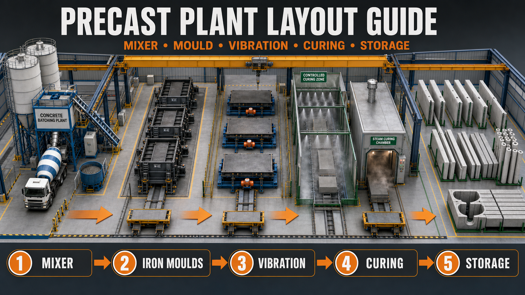
Precast Plant Layout Guide: Mixer, Mould, Vibration, Curing and Storage Planning
Precast Plant Layout Guide: Mixer, Mould, Vibration, Curing and Storage Planning
A precast plant layout directly affects production capacity, material movement, concrete quality and workplace safety.
Placing equipment wherever space is available can create unnecessary trolley movement, concrete delays, unsafe crane operations and congestion around the moulds.
An efficient plant should follow a clear production sequence:
Raw Material Storage → Concrete Mixing → Concrete Transport → Iron Mould Preparation → Reinforcement and Insert Placement → Concrete Casting → Vibration → Curing → Demoulding → Inspection → Finished-Product Storage → Dispatch
The objective is to keep materials moving forward without unnecessary backtracking or crossing between production activities.
Why Precast Plant Layout Is Important
A properly planned layout helps a precast manufacturer to:
• Reduce material-handling time • Improve daily production capacity • Maintain concrete consistency • Prevent production bottlenecks • Use factory space efficiently • Improve crane and trolley movement • Reduce product damage • Support safer working conditions • Simplify quality inspection • Improve mould utilisation • Reduce labour requirements • Make future expansion easier
The layout should be developed according to the products being manufactured rather than copied from an unrelated precast factory.
Information Required Before Planning the Layout
Before selecting equipment positions, collect the following information:
• Type of precast products • Product dimensions • Product weight • Daily production target • Number of casting cycles • Number and size of iron moulds • Concrete quantity per shift • Reinforcement requirements • Vibration method • Curing method • Demoulding process • Crane capacity • Trolley movement • Available factory area • Open-yard area • Storage duration • Dispatch frequency • Future production plans
A plant manufacturing small fencing products requires a different arrangement from a plant producing large wall panels, poles, drains or bridge components.
Main Areas of a Precast Plant
A complete precast plant may include:
• Raw-material storage • Cement and admixture storage • Batching and mixing area • Reinforcement fabrication area • Iron mould preparation area • Casting area • Vibration area • Curing area • Demoulding area • Product inspection area • Repair and finishing area • Finished-product storage • Mould maintenance workshop • Equipment-maintenance area • Quality-control laboratory • Utility area • Internal transport routes • Dispatch zone
Each area should connect logically with the next production stage.
Raw-Material Storage Planning
Raw materials should be stored close enough to the batching plant to reduce handling time while remaining protected from contamination.
Aggregate Storage
Different aggregate sizes should be stored separately to prevent mixing.
The storage area should have:
• Stable flooring • Proper drainage • Separation walls or bins • Vehicle access • Controlled loading routes • Protection from mud and contamination • Safe loader movement
Cement Storage
Cement may be stored in silos or another suitable protected system.
The storage and feeding arrangement should minimise moisture exposure, dust generation and manual handling.
Admixture Storage
Chemical admixtures should be stored according to the supplier’s requirements.
The area should protect containers and dosing systems from contamination, extreme temperature and accidental damage.
Mixer and Batching Plant Location
The mixer should be located so that concrete can reach every active mould within the permitted handling time.
Important considerations include:
• Distance from aggregate storage • Cement feeding arrangement • Water supply • Admixture dosing • Concrete discharge height • Mixer cleaning • Drainage • Electrical supply • Maintenance access • Concrete transport route • Dust and noise control
The mixer should not be positioned where delivery vehicles block normal production movement.
Central Mixer vs Multiple Mixing Points
A central mixer can supply several production lines and simplify material control.
However, a large plant may require multiple mixing points if products are located far apart or use different concrete mixes.
The correct arrangement depends on:
• Concrete demand • Number of production lines • Factory dimensions • Concrete transport method • Required mix consistency • Production schedule
Concrete Transport Planning
Fresh concrete may be moved using:
• Concrete shifting trolley • Crane-operated concrete bucket • Rail trolley • Forklift-compatible bucket • Conveyor • Pump • Automated distribution system
The selected route should be:
• Short • Direct • Level where possible • Free from unnecessary turns • Separate from finished-product movement • Suitable for the loaded equipment • Easy to clean • Properly drained
Concrete transport routes should not cross pedestrian areas without appropriate controls.
Iron Mould Preparation Area
Heavy-duty iron precast moulds require regular cleaning, inspection, alignment and release-agent application.
The preparation area should provide sufficient space for:
• Opening shutters • Cleaning casting surfaces • Inspecting locks and hinges • Checking mould dimensions • Applying release agent • Installing reinforcement cages • Positioning inserts • Repairing minor defects • Moving lifting equipment
The mould should be placed on a stable, level and load-bearing foundation.
Irregular flooring can twist the mould frame and affect product dimensions.
Iron Mould Positioning
Moulds should be arranged according to their casting and demoulding requirements.
Important planning factors include:
• Mould length and width • Shutter opening space • Worker access • Concrete pouring direction • Vibrator location • Crane coverage • Product lifting direction • Cleaning access • Lock and hinge operation • Maintenance requirements
Moulds should not be installed so close together that shutters cannot open safely.
Wall Panel Mould Layout
Wall panel moulds require space for:
• Reinforcement cage placement • Large inserts • Concrete distribution • Shutter operation • Panel lifting • Panel shifting trolley • Storage-rack loading
The lifting path should remain free from equipment and other moulds.
Pole Mould Layout
Long pole moulds require sufficient straight-line space for:
• Cage insertion • Concrete pouring • Vibration • Mould opening • Balanced pole lifting • Product movement • Cleaning and maintenance
Crane coverage and lifting-beam requirements should be considered before fixing the mould position.
Drain Mould Layout
Drain moulds require space for shutter opening, core removal and product turning.
The layout should prevent freshly demoulded drains from blocking the next casting cycle.
Reinforcement Fabrication Area
The reinforcement area should be located close to the moulds but separated from wet concrete operations.
It may include:
• Bar storage • Cutting equipment • Bending equipment • Cage assembly tables • Mesh preparation • Welding or tying stations • Cage inspection area • Finished-cage storage
Completed cages should move to the mould without crossing finished-product or concrete-transport routes.
Vibration System Planning
Concrete vibration affects compaction, surface finish and mould performance.
Common systems include:
• Shutter vibrators • Vibrator tables • Internal vibrators • External vibration systems • Combined vibration arrangements
Shutter Vibrator Layout
Shutter vibrators are mounted directly on the iron mould.
The layout should provide:
• Electrical or pneumatic connections • Safe cable routing • Access for maintenance • Suitable vibrator positioning • Isolation from sensitive equipment • Noise-control measures • Strong mould supports
Vibrator Table Layout
A vibrator table requires a stable foundation and adequate space for placing and removing moulds.
The equipment should be located where loaded mould movement is safe and efficient.
Vibration Isolation
Vibration should not affect:
• Measuring equipment • Quality laboratory instruments • Stored finished products • Nearby building components • Other casting operations • Mould alignment
Foundation and isolation requirements should be determined according to the equipment manufacturer’s recommendations.
Curing Area Planning
The curing area should be positioned after the casting stage and before demoulding or storage, depending on the selected production process.
Water-Curing Area
A water-curing area requires:
• Reliable water supply • Drainage • Water collection • Slip-resistant flooring • Product access • Suitable racks • Protection from contamination • Water-recycling options
Water should not flow into electrical areas, mould-maintenance zones or vehicle routes.
Steam-Curing Area
Steam curing may require:
• Insulated curing enclosure • Steam generator or boiler • Pipe network • Temperature sensors • Control system • Condensate drainage • Ventilation • Equipment-maintenance access • Safety barriers
The chamber should be located where products can enter and leave without unnecessary turning or backtracking.
Covered Curing Area
Some products may be cured under insulated covers or within controlled bays.
The area should allow covers to be installed and removed safely without interfering with crane movement.
Demoulding Area Planning
Demoulding requires enough space to open the mould and lift the product safely.
The area should include:
• Clear shutter-opening space • Crane or lifting-equipment access • Product-support blocks • Inspection space • Repair space • Safe worker access • Defined exclusion zones • Route to continued curing or storage
A freshly demoulded product should not be moved over active work areas unless the handling system has been designed for that operation.
Crane Coverage
Crane planning should consider the heaviest load, not only the weight of the finished product.
The lifting system may need to handle:
• Iron mould components • Reinforcement cages • Concrete buckets • Finished precast products • Lifting beams • Maintenance equipment
Important crane factors include:
• Safe working load • Required lifting height • Hook approach • Travel direction • Product length • Lifting-beam length • Crane coverage • Number of simultaneous operations
Crane paths should not create conflicts between casting, demoulding and storage activities.
Product Inspection Area
A dedicated inspection zone helps prevent defective products from entering finished-product storage.
The area may be used for:
• Dimensional inspection • Surface inspection • Crack checking • Strength-record verification • Insert-position checking • Product identification • Minor approved repairs • Documentation
The floor should be level so that dimensional measurements remain accurate.
Finished-Product Storage Planning
Storage is often one of the largest areas in a precast plant.
Products should be stored according to their shape, weight, lifting requirements and approved support locations.
Wall Panel Storage
Wall panels may require engineered storage racks.
The storage system should:
• Keep panels stable • Support products at approved points • Prevent panel-to-panel damage • Allow lifting-access space • Provide identification access • Maintain safe rack capacity
Concrete Pole Storage
Poles should be stored on suitable supports located according to the approved handling procedure.
Incorrect support spacing can cause cracking or deformation.
Precast Drain Storage
Drains should be placed on stable ground with suitable support.
Stacking should follow an approved arrangement that considers product strength, geometry and lifting access.
First-In, First-Out System
A planned storage sequence helps older products move to dispatch first after achieving the required strength.
Each product should have clear identification, such as:
• Product type • Casting date • Batch number • Inspection status • Strength status • Project reference • Dispatch approval
Dispatch Area Planning
The dispatch area should allow trucks to enter, load and exit without interfering with production.
Important features include:
• Vehicle-turning space • Loading-crane access • Product staging area • Safe loading zone • Documentation point • Product-securing space • Controlled entry and exit • Road suitable for loaded vehicles
Finished products should not travel back through the wet production area.
Internal Traffic Planning
The plant should define separate routes for:
• Pedestrians • Concrete trolleys • Forklifts • Loaders • Cranes • Finished-product transport • Delivery trucks • Maintenance vehicles
Use floor markings, barriers and signs where required.
Blind corners and route crossings should be minimised.
Drainage Planning
Precast production generates water from:
• Mould cleaning • Mixer washing • Water curing • Floor cleaning • Concrete transport equipment • Rainfall in open areas
The layout should include suitable drainage, settlement arrangements and water-recycling systems.
Cement slurry should not be discharged directly into ordinary drains without appropriate treatment.
Electrical and Utility Planning
Utilities should be positioned according to the needs of each production area.
These may include:
• Electrical power • Water • Compressed air • Steam • Lighting • Ventilation • Drainage • Communication systems • Emergency equipment
Cables and hoses should not create tripping hazards or cross vehicle routes without protection.
Mould Maintenance Workshop
Heavy-duty iron moulds require periodic welding, straightening and component replacement.
A maintenance workshop may include:
• Welding equipment • Cutting equipment • Straightening tools • Measuring instruments • Spare locks and hinges • Iron plates and sections • Workbenches • Lifting equipment • Ventilation and fire-safety equipment
The workshop should be separated from active concrete casting and curing operations.
Quality-Control Laboratory
A quality-control area may be used for:
• Raw-material testing • Concrete workability checks • Test-specimen preparation • Strength-test records • Dimensional inspection tools • Calibration records • Mix-design documentation • Production traceability
It should be protected from heavy vibration, dust and uncontrolled temperature conditions.
Precast Plant Layout Options
Straight-Line Layout
Materials and products move in one primary direction.
Advantages:
• Simple material flow • Less backtracking • Easier supervision • Suitable for long factories
Possible limitation:
• Requires sufficient length
U-Shaped Layout
Production begins and ends near the same side of the plant.
Advantages:
• Compact arrangement • Shared access to utilities • Suitable for limited factory length
Possible limitation:
• Requires careful traffic planning
Parallel Production Lines
Multiple casting lines operate side by side.
Advantages:
• Suitable for different product types • Supports higher production • Allows phased expansion
Possible limitation:
• Crane and concrete distribution require careful coordination
Fixed Mould Layout
Large iron moulds remain in one location while materials and equipment move to them.
This arrangement may be suitable for wall panels, large columns and infrastructure products.
Mobile Mould Layout
Smaller moulds move between casting, vibration and curing stations.
This arrangement may be suitable for high-volume repetitive products.
Common Precast Plant Layout Mistakes
Mixer Located Too Far From Moulds
Long transport time can affect concrete consistency and increase labour.
Insufficient Mould-Opening Space
Closely positioned moulds may prevent safe shutter operation and maintenance.
Crossing Material Routes
Reinforcement, fresh concrete and finished products should not repeatedly cross the same narrow route.
Poor Crane Coverage
A crane that cannot reach the complete mould or storage area creates unnecessary product shifting.
Inadequate Drainage
Standing water creates cleaning, corrosion and workplace-safety problems.
Undersized Storage Area
Production may stop if finished products occupy the casting or transport area.
Ignoring Future Expansion
Utilities, cranes and traffic routes should allow additional moulds or production lines where expansion is expected.
Unstable Mould Foundation
An uneven base can twist an iron mould, causing dimensional variation and slurry leakage.
No Dedicated Maintenance Area
Repair work conducted inside an active production line can delay casting and create safety risks.
Placing the Laboratory Near Vibration Equipment
Heavy vibration can affect testing and measuring equipment.
How to Calculate the Number of Moulds Required
The number of moulds depends on:
• Daily production target • Units produced per mould per cycle • Number of casting cycles • Demoulding time • Curing system • Cleaning and preparation time • Expected maintenance downtime • Product rejection allowance
A simplified planning formula is:
Moulds Required = Daily Production Target ÷ Output Per Mould Per Day
The final quantity should include practical allowances for setup, maintenance and production variation.
Plant Layout Planning Checklist
Production Information:
• Product types confirmed • Product dimensions available • Daily capacity defined • Casting cycle calculated • Number of iron moulds estimated • Concrete demand calculated
Equipment Planning:
• Mixer capacity selected • Concrete transport system selected • Vibration method selected • Curing method selected • Crane capacity verified • Shifting equipment planned
Area Planning:
• Raw-material storage allocated • Reinforcement area allocated • Mould preparation area allocated • Casting area allocated • Curing area allocated • Demoulding area allocated • Inspection area allocated • Finished storage allocated • Maintenance workshop allocated • Dispatch area allocated
Safety and Utilities:
• Pedestrian routes marked • Vehicle routes defined • Crane paths checked • Drainage planned • Electrical supply planned • Water supply planned • Lighting and ventilation planned • Emergency access maintained
Final Conclusion
An efficient precast plant layout should follow the actual production sequence from raw-material storage to finished-product dispatch.
The mixer should remain close enough to the casting area for quick concrete delivery. Heavy-duty iron moulds should have sufficient space for cleaning, cage placement, pouring, vibration and shutter opening.
The curing area should match the selected water, covered or steam-curing method. Demoulding, inspection and storage areas should support safe product handling without interrupting active production.
Paras Steel Industries manufactures customised heavy-duty iron precast moulds and related production equipment according to product dimensions, factory space and daily output requirements.
For plant and mould planning, share your factory dimensions, precast product drawings, daily production target, curing method and material-handling arrangement with Paras Steel Industries.