
Precast Mould Quality Guide
Precast Mould Dimensional Tolerance: How to Check Alignment, Squareness and Accuracy
Dimensional accuracy is essential for producing precast components that fit correctly at the project site. This guide explains how to inspect the alignment, squareness, straightness and dimensions of heavy-duty iron precast moulds.
By Paras Steel Industries ·
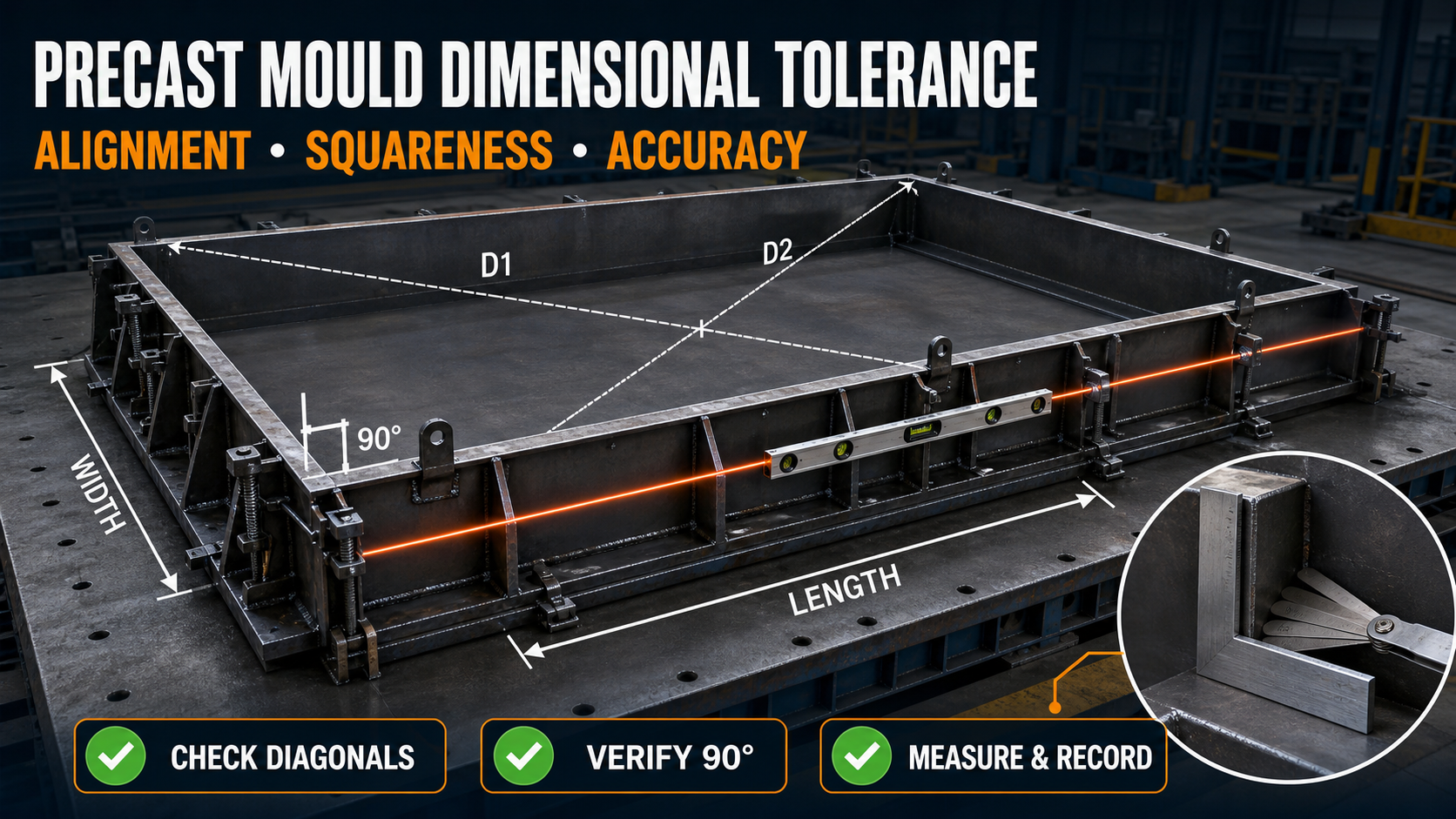
Precast Mould Dimensional Tolerance: How to Check Alignment, Squareness and Accuracy
Precast Mould Dimensional Tolerance: How to Check Alignment, Squareness and Accuracy
Dimensional accuracy is one of the most important requirements in precast concrete production. Even a strong precast component may create installation problems if its length, width, thickness, diagonals or insert positions are incorrect.
The dimensional accuracy of a finished product depends heavily on the condition and setup of its mould. A heavy-duty iron precast mould must remain straight, square and stable during assembly, concrete pouring, vibration and demoulding.
Regular mould inspection helps manufacturers identify misalignment before it results in rejected products, installation delays or costly site modifications.
What Is Dimensional Tolerance in a Precast Mould?
Dimensional tolerance is the permitted variation between the specified dimension and the actual measured dimension.
For example, a product drawing may specify a particular length, width or thickness. The applicable project specification then defines how much variation is acceptable.
Tolerance does not mean that any dimensional variation is acceptable. It provides a controlled limit within which the precast component can perform and fit as intended.
Permissible tolerance can vary according to:
• Type of precast product • Product dimensions • Structural requirements • Connection details • Architectural finish • Applicable project specification • Installation method • Customer requirements • Relevant codes and standards
The mould manufacturer and precast producer should always work according to the approved product drawing and project tolerance requirements.
Why Mould Accuracy Is Important
Accurate iron moulds help produce precast components with consistent dimensions and predictable installation performance.
Correct mould geometry helps to:
• Maintain product length, width and thickness • Produce square corners • Keep opposite sides parallel • Maintain straight edges • Control panel flatness • Position lifting anchors correctly • Maintain connection locations • Improve joint alignment at the project site • Reduce finishing and repair work • Prevent product rejection • Support faster installation • Improve interchangeability of repeated components
A small error in one mould can be repeated across every component manufactured from it. This makes mould inspection an essential part of quality control.
Important Dimensions to Check
Before casting, the following mould dimensions should be inspected:
• Internal length • Internal width • Product thickness • Corner angles • Diagonal measurements • Sidewall verticality • Plate straightness • Base-frame level • Opposite-side parallelism • Insert locations • Lifting-anchor positions • Opening dimensions • Joint and rebate dimensions • Chamfer dimensions • Block-out positions • Cover-related dimensions
The required measurements depend on the product design and approved drawing.
Tools Used to Check Precast Mould Accuracy
Different measuring tools may be required according to the mould size and required precision.
Common inspection tools include:
• Measuring tape • Steel ruler • Engineer’s square • Spirit level • Straightedge • Feeler gauge • Vernier caliper • Depth gauge • Plumb bob • String line • Laser level • Laser distance meter • Total station for large moulds • Calibrated templates and jigs
Measuring instruments should be maintained properly and calibrated according to the company’s quality system.
How to Check the Length and Width of a Mould
Clean the internal mould surfaces before taking measurements. Hardened concrete, rust, debris or an incorrectly positioned gasket can affect the reading.
Measure the internal length and width at multiple locations rather than checking only one point.
For a long wall panel mould, measurements may be taken at:
• Both ends • Centre position • Intermediate locations • Top of the shutter • Bottom of the shutter
Differences between measurements can indicate tapering, plate bending or incorrect shutter alignment.
Compare every reading with the approved drawing and record the result.
How to Check Mould Squareness
Squareness confirms whether the mould corners are positioned at the required angle. A mould that is not square may produce a precast component with unequal diagonals and installation difficulties.
Diagonal Measurement Method
For a rectangular mould:
1. Measure from the first corner to the diagonally opposite corner. 2. Record the measurement. 3. Measure the other diagonal. 4. Compare the two readings.
If both diagonal measurements are equal, the mould is generally square. If they differ, the mould may be out of square.
The acceptable difference must be determined from the approved tolerance requirement.
Engineer’s Square Method
An engineer’s square can be used to inspect smaller corners and mould components.
Place the square against the two adjoining surfaces and check for visible gaps. A feeler gauge may be used to measure a small gap where greater accuracy is required.
For large moulds, diagonal measurement or surveying equipment is usually more practical.
How to Check Mould Alignment
Alignment determines whether the shutters, edges and supporting members follow the required line.
String-Line Method
Stretch a string line along the length of the mould without allowing it to touch intermediate sections.
Measure the distance between the string and the mould surface at several points. Changes in the gap may indicate bending or misalignment.
Straightedge Method
Place a suitable straightedge against the mould plate or edge.
Use a feeler gauge to identify gaps between the straightedge and iron surface. This method is useful for detecting local plate deformation.
Laser Method
A laser level or alignment laser can provide a reference line for long moulds.
It is especially useful for checking:
• Long wall panel moulds • Column moulds • Pole moulds • Bridge component moulds • Production beds • Multiple moulds installed in one line
The laser equipment should be positioned on a stable surface and verified before use.
How to Check Straightness
Mould straightness affects the edges and overall appearance of the precast product.
To check straightness:
1. Clean the mould surface. 2. Place a straightedge or string line along the required edge. 3. Inspect the complete length. 4. Measure the largest visible gap. 5. Compare the reading with the approved tolerance.
Check both the mould plate and supporting frame. A straight plate installed on a twisted frame may still move out of position during casting.
How to Check Mould Level
A mould that is not level can cause:
• Unequal product thickness • Concrete flowing toward one side • Incorrect top-surface elevation • Frame twisting • Joint gaps and slurry leakage • Misaligned inserts
Use a spirit level or laser level to check the base frame and critical mould surfaces.
For a large iron mould, check the level at several positions. Adjust the supporting points with suitable engineered arrangements instead of using unstable temporary packing.
How to Check Sidewall Verticality
Verticality is important for columns, poles, deep panels and other products with upright shutters.
A spirit level, plumb bob or laser can be used to check whether the sidewall is vertical.
Take measurements at multiple locations because one part of a long shutter may be vertical while another section is tilted.
Also check the shutter after all locks are tightened. Locking pressure can change its position.
How to Check Parallelism
Opposite mould shutters must remain parallel when the product requires a uniform width or thickness.
Measure the distance between opposite shutters at multiple locations:
• Both ends • Centre • Top • Bottom • Intermediate positions
A gradual change in measurement may indicate tapering. A local change may indicate plate bulging, debris at the joint or a damaged stiffener.
How to Check Product Thickness
Product thickness is controlled by the distance between mould surfaces or by the position of the side shutters.
Measure the internal spacing at several points. Do not assume the thickness is correct because one end matches the drawing.
For wide or deep moulds, concrete pressure may push the shutters outward during casting. Therefore, the mould must have adequate locks, tie arrangements and structural stiffeners.
How to Check Insert and Opening Positions
Precast products may include:
• Lifting anchors • Connection plates • Sleeves • Bolt holes • Electrical openings • Pipe openings • Block-outs • Rebates • Grooves • Embedded components
Check each insert position from fixed mould reference points. Avoid measuring only from another insert because one incorrect position can transfer the error to several components.
Verify:
• Horizontal position • Vertical position • Depth • Orientation • Distance from edges • Centre-to-centre spacing • Stability during vibration
Templates and jigs can improve repeatability when identical insert arrangements are used regularly.
When Should Mould Dimensions Be Checked?
Dimensional inspection should not be limited to the first production cycle.
Mould dimensions should be checked:
• After initial fabrication • During trial assembly • Before the first casting • At defined production intervals • After shifting or transportation • After major maintenance • After welding or plate repair • After replacing locks or hinges • After abnormal vibration • When product dimensions become inconsistent • Before restarting a mould stored for a long period
Critical measurements may also be checked before every casting cycle.
Pre-Pour Dimensional Inspection Process
A practical pre-pour inspection can follow these steps:
1. Clean the mould completely. 2. Place it on a level and stable platform. 3. Assemble all shutters correctly. 4. Engage locks and clamps in the normal sequence. 5. Check internal length and width. 6. Measure both diagonals. 7. Check plate straightness. 8. Verify the level of the base frame. 9. Check sidewall verticality. 10. Verify product thickness. 11. Confirm insert and opening positions. 12. Inspect joints for visible gaps. 13. Record all measurements. 14. Correct nonconformities before pouring concrete.
Measurements should be taken after the mould has been fully assembled and locked because its geometry can change during closure.
Why Mould Dimensions Change Over Time
An iron precast mould can lose accuracy due to repeated production and handling.
Common reasons include:
• Concrete pressure • Excessive vibration • Inadequate stiffeners • Worn hinges and locks • Loose bolts • Rough demoulding • Incorrect crane lifting • Impact during shifting • Welding heat distortion • Uneven factory flooring • Concrete buildup at joints • Corrosion • Poor storage • Uncontrolled repair work
Regular inspection helps detect small changes before they become major structural problems.
Role of Iron Plate Thickness and Stiffeners
Mould dimensional accuracy depends on both the casting plate and its supporting structure.
A suitable iron plate thickness helps resist local bending. Angle sections, C-channels or H-beams provide additional rigidity according to the mould size and concrete pressure.
Important structural factors include:
• Iron plate thickness • Stiffener section • Stiffener spacing • Frame design • Cross-bracing • Locking-point locations • Weld quality • Supporting arrangement • Lifting-point design
Simply using a thicker plate does not guarantee accuracy if the frame is weak or poorly aligned.
How Vibration Affects Dimensional Accuracy
Concrete vibration creates dynamic forces within the mould.
Excessive vibration or incorrectly positioned vibrators can:
• Loosen locks • Move shutters • Increase joint gaps • Cause plate deformation • Damage welded connections • Shift inserts • Affect mould alignment
Vibrators should be mounted at suitable locations and operated according to the concrete mix, mould design and production requirements.
How to Correct an Out-of-Alignment Mould
The correct repair method depends on the cause and severity of the dimensional error.
Possible corrective actions include:
• Cleaning the mould joints • Adjusting locks and clamps • Replacing worn pins or hinges • Levelling the supporting platform • Tightening loose fasteners • Repositioning removable shutters • Repairing damaged stiffeners • Controlled straightening of bent plates • Replacing severely damaged plates • Correcting insert templates • Repairing the base frame • Realigning the mould with suitable fixtures
Structural repairs and welding should be completed by qualified personnel. The mould must be measured again after repair and before returning to production.
Common Dimensional Inspection Mistakes
Checking Only One Measurement
Measuring only the length or width cannot confirm squareness, straightness or parallelism.
Measuring Before Tightening Locks
The mould geometry may change when clamps and locks are engaged. Final measurements should be taken in the normal casting condition.
Using Uncalibrated Tools
A damaged or inaccurate measuring instrument can produce unreliable inspection results.
Ignoring Concrete Buildup
Hardened concrete at joints can prevent correct mould closure and alter internal dimensions.
Using Flexible Reference Points
Measurements should be taken from fixed and clearly defined reference points.
Forcing the Mould Into Position
Excessive tightening may temporarily close a gap but can introduce bending or stress into the frame.
Failing to Record Measurements
Without inspection records, it becomes difficult to identify gradual mould movement or repeated problems.
Precast Mould Inspection Record
A mould inspection record can include:
• Mould identification number • Product name • Drawing number • Inspection date • Measuring instrument • Required dimension • Permitted tolerance • Actual measurement • Acceptance status • Observed defect • Corrective action • Inspector’s name • Approval status
Maintaining inspection records improves traceability and preventive maintenance planning.
Daily Accuracy Checklist
Before starting production, check:
• Mould is clean • Base frame is level • Shutters are correctly positioned • Locks are fully engaged • Internal dimensions are correct • Diagonals are within the approved tolerance • Plates and edges are straight • Opposite sides are parallel • Sidewalls are vertical where required • Inserts match the approved drawing • Joints are properly closed • Stiffeners and welds are undamaged • Measuring tools are suitable and calibrated
Final Conclusion
Dimensional tolerance in a precast mould directly influences product quality, installation speed and structural coordination.
Length, width, thickness, diagonals, straightness, level, verticality, parallelism and insert positions should be inspected according to the approved product drawing and project tolerance requirements.
A heavy-duty iron precast mould must remain accurate while carrying concrete pressure and vibration loads. Suitable plate thickness, structural stiffeners, reliable locking systems, quality welding and a stable supporting platform are therefore essential.
Paras Steel Industries manufactures customised heavy-duty iron precast moulds according to customer drawings, product dimensions and production requirements. Moulds can be designed with suitable plates, stiffeners, locks and adjustment arrangements to support consistent and accurate precast production.
For customised mould specifications and pricing, share your precast product drawing, required dimensions, tolerance requirements and daily production target with Paras Steel Industries.