
Precast Mould Guide
Precast Garden Bench Mould Assembly: Seat Slope, Backrest Angle and Leg Alignment Guide
Accurate garden bench mould assembly is essential for producing comfortable, stable and visually consistent precast concrete benches. This guide explains how to check the seat slope, backrest angle, leg alignment, mould joints and locking system before casting.
By Paras Steel Industries ·
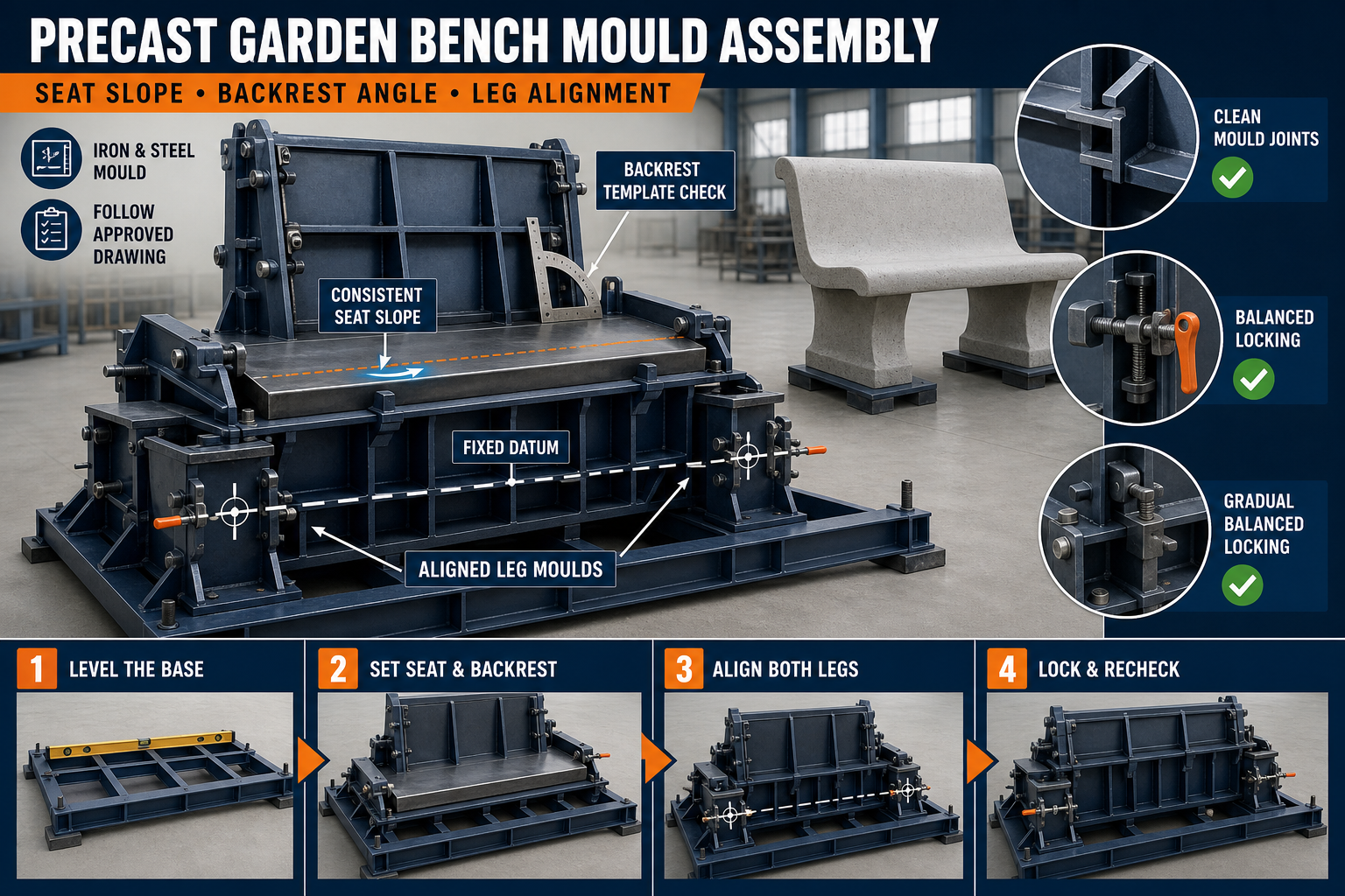
Precast Garden Bench Mould Assembly: Seat Slope, Backrest Angle and Leg Alignment Guide
Precast Garden Bench Mould Assembly Guide
Precast concrete garden benches are widely used in parks, schools, housing societies, public gardens, pathways and commercial landscapes. Their appearance and stability depend heavily on the accuracy of the mould assembly.
Even a strong concrete mix cannot correct a poorly assembled mould. An incorrect seat slope may make the bench uncomfortable, a wrongly positioned backrest can affect its appearance and misaligned legs may cause instability during installation.
A properly fabricated heavy-duty iron garden bench mould helps maintain the required shape, dimensions and surface finish. However, operators must assemble, align and lock every section correctly before casting.
This guide explains the garden bench mould assembly process, including seat slope, backrest angle, leg alignment and final quality checks.
What Is a Precast Garden Bench Mould?
A precast garden bench mould is an iron or structural-steel fabrication used to manufacture concrete bench components. Depending on the product design, the mould may produce a complete bench or separate parts such as the seat, backrest and supporting legs.
A garden bench mould may include:
• Fabricated iron casting plates • Seat-forming section • Backrest-forming section • Leg or pedestal moulds • Side shutters • Base frame and stiffeners • Hinges, pins and locking clamps • Adjustable alignment points • Chamfer-forming strips • Decorative inserts where required • Lifting provisions for mould handling
The exact configuration should follow the approved garden bench drawing and required production method.
Why Correct Mould Assembly Is Important
Correct assembly ensures that all bench components fit together properly after casting. It also helps prevent dimensional differences between production cycles.
Accurate garden bench mould assembly helps achieve:
• Consistent seat dimensions • Correct seat slope • Uniform backrest position • Properly aligned supporting legs • Stable installation • Cleaner concrete edges • Reduced slurry leakage • Easier demoulding • Repeatable production quality • Longer mould service life
Assembly errors can result in rocking benches, mismatched components, uneven gaps and difficult installation at the project site.
Prepare the Mould Before Assembly
Before assembling the mould, place all mould components on a clean and level production floor.
Complete the following checks:
• Remove hardened concrete and slurry • Clean the casting surfaces • Inspect the base frame • Check shutters for bending or distortion • Examine hinges and locking components • Clean bolts, pins and threaded parts • Inspect welded joints • Check decorative liners or inserts • Confirm that all required components are available • Verify the approved production drawing
Do not begin assembly if any important mould component is bent, cracked or heavily damaged.
Check the Base Frame Level
The base frame establishes the reference for the complete mould. If it is twisted or placed on an uneven floor, the seat, backrest and legs may not align correctly.
To prepare the base:
1. Position the mould on a firm and level surface. 2. Check the base frame in both directions. 3. Support all specified load-bearing points. 4. Remove debris from underneath the frame. 5. Correct any visible rocking or twisting. 6. Establish a fixed reference or datum point. 7. Recheck the level after tightening the supports.
Do not attempt to correct a distorted base only by forcing the shutters into position.
Seat Slope Alignment
The seat surface of a garden bench may include a designed slope for comfort and drainage. The required slope depends on the approved product drawing.
During mould assembly:
• Identify the front and rear edges of the seat section • Position the seat plate according to the fixed datum • Check the slope with a suitable measuring instrument • Confirm that the slope remains consistent across the width • Inspect the transition between the seat and backrest • Tighten supports without changing the established position • Recheck the slope after locking all shutters
An excessive slope can make the bench uncomfortable, while an incorrect reverse slope may allow rainwater to collect on the seat.
The required slope should always follow the approved garden bench drawing rather than a general assumed value.
Backrest Angle Setting
The backrest angle affects comfort, appearance and the connection between the seat and backrest. It must remain consistent throughout the production cycle.
To set the backrest section:
1. Position the backrest mould plate against its supports. 2. Align its lower edge with the seat reference. 3. Install the specified brackets or adjustable supports. 4. Check the angle using an angle gauge or approved template. 5. Compare both ends of the backrest. 6. Tighten the locking points gradually. 7. Recheck the angle after final tightening.
The angle should not be estimated visually. Always use the approved drawing, checking template or measurement system.
Backrest Alignment Checks
In addition to the angle, inspect:
• Backrest height • Side-to-side level • Centre alignment • Distance from the seat edge • Position of reinforcement and inserts • Decorative pattern orientation • Joint condition between mould sections • Consistency at both ends
A backrest that is correctly angled but laterally displaced may still create an unacceptable finished component.
Leg Alignment and Spacing
The supporting legs or pedestals must be correctly spaced and aligned to prevent rocking after installation. Both legs should transfer the bench load evenly to the foundation or finished ground.
When assembling leg moulds:
• Establish the centreline of the seat • Mark leg positions from a fixed datum • Check equal offset from both sides where required • Confirm that the leg faces are parallel • Check the top connection surface • Maintain the required spacing • Inspect vertical alignment • Lock each mould without shifting its position
Avoid measuring each leg from the previously positioned component. Measuring from one fixed datum helps reduce accumulated errors.
Checking Leg Verticality
Use a suitable measuring tool to confirm that the leg moulds are vertical according to the approved design.
Check verticality:
• Along the bench length • Across the bench width • At both leg faces • After initial positioning • After locking • Before concrete placement
Incorrect verticality can create installation problems even when the spacing between the legs appears correct.
Alignment of Separate Bench Components
Some garden benches are produced as separate seat, backrest and leg components. These parts are assembled after curing.
For separate components, confirm:
• Matching connection locations • Correct bolt or insert positions • Compatible seat and leg dimensions • Uniform backrest-support locations • Proper orientation of embedded parts • Adequate clearance for assembly • Consistent identification of matching parts
Where possible, use templates or checking fixtures to maintain repeatability between production batches.
Locking the Iron Mould
After completing the initial alignment, lock the mould gradually. Tightening one area completely before the others may pull the shutters out of position.
A suitable locking sequence is:
1. Install all shutters loosely. 2. Align the base and main reference points. 3. Position the seat and backrest sections. 4. Set the leg moulds. 5. Engage all locks lightly. 6. Tighten opposing locks gradually. 7. Check joint closure. 8. Recheck the complete assembly. 9. Complete final tightening.
Locks should hold the mould securely without creating visible deformation.
Preventing Slurry Leakage
Concrete slurry can escape through gaps between mould sections. Leakage may create fins, honeycombing and dimensional defects.
To reduce leakage:
• Clean all joint surfaces • Check flange alignment • Replace damaged sealing material • Tighten locks evenly • Repair distorted shutter edges • Inspect corners and insert locations • Use an approved sealing method where required • Avoid excessive gaps between mould sections
Do not use temporary materials that can contaminate the concrete surface or affect dimensional accuracy.
Reinforcement and Insert Placement
After assembling the mould, position the reinforcement cage and embedded components according to the approved structural drawing.
Check:
• Reinforcement size and spacing • Required concrete cover • Cage position • Connection inserts • Lifting inserts • Bench assembly inserts • Decorative components • Clearance from mould surfaces
Reinforcement must not force the shutters or change the established seat slope, backrest angle or leg alignment.
Applying Mould-Release Agent
Apply a suitable mould-release agent before placing reinforcement when required by the production procedure.
The release agent should be:
• Compatible with precast concrete • Applied to clean casting surfaces • Distributed in a thin and uniform layer • Prevented from pooling in corners • Kept away from reinforcement bond areas • Used according to the manufacturer’s instructions
Excessive application may cause stains, pinholes or an uneven concrete finish.
Pre-Casting Assembly Checklist
Before concrete placement, verify:
• Base frame level and stability • Seat slope • Backrest angle • Backrest alignment • Leg position and spacing • Leg verticality • Locking-system engagement • Joint closure • Reinforcement position • Concrete cover • Insert locations • Casting-surface cleanliness • Release-agent application • Overall mould dimensions
Record the inspection according to the plant’s quality-control procedure.
Concrete Placement and Vibration
Concrete should be placed evenly without creating excessive pressure on one mould section.
During casting:
• Place concrete in a controlled sequence • Avoid dropping concrete from excessive height • Monitor shutter movement • Use suitable vibration • Avoid direct impact between the vibrator and mould • Check locks during concrete placement • Stop casting if abnormal movement appears • Finish exposed surfaces according to the product requirement
Excessive vibration can cause slurry leakage, segregation and movement of reinforcement or embedded components.
Safe Demoulding Process
Do not open the mould until the concrete has achieved the required stripping strength.
During demoulding:
1. Remove hardened slurry from locking points. 2. Support heavy shutters before unlocking. 3. Release locks gradually. 4. Open shutters in the designed direction. 5. Avoid striking concrete edges. 6. Lift components using approved lifting points. 7. Protect corners during handling. 8. Place finished parts on level supports.
Never use excessive hammering or uncontrolled pulling to release the concrete.
Common Garden Bench Mould Assembly Errors
Incorrect Seat Slope
This can cause discomfort or water accumulation. Recheck the seat plate before and after locking.
Unequal Backrest Angle
A difference between the two ends may twist the finished backrest. Use an approved template or measurement tool.
Misaligned Legs
Incorrect spacing or verticality can make the installed bench unstable. Measure both legs from a fixed datum.
Loose Locks
Loose locking points can allow shutter movement and slurry leakage during vibration.
Over-Tightened Locks
Excessive tightening may distort the iron shutter and change the component profile.
Dirty Joint Surfaces
Hardened concrete between joints can prevent complete closure and create fins on the finished product.
Quality Checks After Demoulding
Inspect every finished bench component for:
• Overall dimensions • Seat slope and level • Backrest profile • Leg spacing • Connection alignment • Surface finish • Edge and corner condition • Insert locations • Cracks or honeycombing • Stability during trial assembly
Acceptance requirements should follow the approved product drawing and project quality plan.
Iron Mould Maintenance
Regular maintenance helps protect mould accuracy and production quality.
Recommended practices include:
• Clean the mould after every casting cycle • Remove slurry from hinges and locks • Lubricate moving components • Inspect welded joints • Check the base frame for distortion • Protect casting surfaces from corrosion • Store removable parts correctly • Repair damaged shutters before reuse • Verify alignment at planned intervals
Avoid uncontrolled heating and heavy hammering because they may distort the iron mould.
Conclusion
Successful garden bench mould assembly depends on establishing a level base, maintaining the specified seat slope, setting the correct backrest angle and positioning the legs from a fixed reference point.
All measurements should follow the approved garden bench drawing because design requirements can vary between projects. Careful locking, joint inspection and pre-casting checks help reduce defects and improve production consistency.
Paras Steel Industries manufactures heavy-duty iron and structural-steel precast moulds according to customer requirements and approved drawings. A correctly designed and assembled garden bench mould can support accurate production, easier demoulding and consistent finished components.