
Precast Infrastructure Moulds
Pocket Footing Mould Core: Taper, Centre Alignment and Easy Demoulding Guide
A tapered and correctly centred pocket core forms the column socket inside a precast footing. This guide explains core taper, centre alignment, locking, casting, demoulding and maintenance requirements.
By Paras Steel Industries ·
Pocket Footing Mould Core: Taper, Centre Alignment and Easy Demoulding Guide
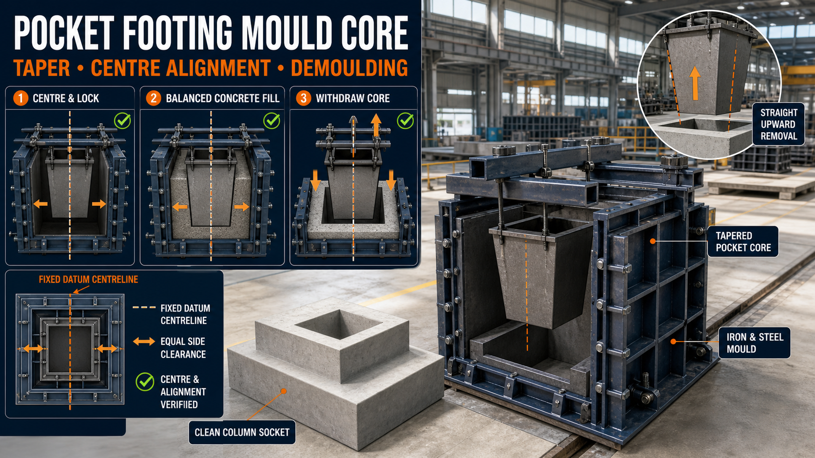
Pocket Footing Mould Core: Taper, Centre Alignment and Easy Demoulding Guide
Precast pocket footings provide ready-made foundations for columns, fencing posts, industrial structures and other precast components. A central socket or pocket is formed inside the footing so that the required column can be installed and grouted at the project site.
The accuracy of this socket depends largely on the pocket core used inside the mould. If the core is incorrectly sized, tilted or positioned away from the centre, the installed column may not align with the foundation.
A properly designed tapered core creates an accurate socket while providing the clearance required for controlled demoulding.
Paras Steel Industries manufactures heavy-duty iron and IS 2062 steel pocket footing moulds with stepped profiles, suspended tapered cores, quick-release side panels and structural channel reinforcement.
What Is a Pocket Footing Mould?
A pocket footing mould is an iron or steel formwork system used to manufacture a precast concrete foundation with an internal column socket.
The finished product may contain:
• A wide foundation base • One or more stepped levels • An upper pedestal section • A central column pocket • Reinforcement • Lifting and handling provisions • Project-specific anchoring details
Pocket footings may be used for:
• Precast columns • Boundary-wall posts • Security fencing poles • Industrial building frames • Warehouse structures • Highway sign posts • Utility structures • Project-specific foundation systems
The dimensions and reinforcement must follow an approved structural design.
What Is a Pocket Core?
A pocket core is a removable internal steel box used to form the socket inside the concrete footing.
It is positioned above the mould and suspended at the required location before concrete is poured. After curing, the core is removed to expose the finished pocket.
A pocket core may contain:
• Heavy-duty steel plates • Tapered side faces • Top supporting crossbars • Alignment guides • Lifting or pulling points • Locking bolts or clamps • Structural stiffeners • Quick-release connections
The core should be strong enough to resist fresh concrete pressure without bending or changing position.
Why Is Core Taper Important?
A completely straight core may develop considerable friction against the concrete after casting. Concrete shrinkage and surface irregularities can make removal difficult.
A calculated taper reduces the effective core size as it is lifted. This gradually creates clearance between the steel surface and concrete socket.
Benefits of a tapered pocket core may include:
• Easier core removal • Reduced friction • Lower risk of damaged socket edges • Reduced dependence on hammering • Faster demoulding • Better internal surface finish • Lower mould wear • More consistent production cycles
The taper must be based on the approved pocket dimensions and installation requirements. Excessive taper can alter the socket geometry, while insufficient taper may cause sticking.
Pocket Opening vs Pocket Bottom
Because the core is tapered, the opening and bottom of the finished socket may not have identical dimensions.
Before manufacturing the mould, confirm:
• Required pocket opening • Required pocket depth • Bottom dimensions • Column cross-section • Installation clearance • Grout space • Core-removal direction • Permitted dimensional tolerance
The final pocket design should provide sufficient installation and grouting clearance without weakening the footing.
Importance of Centre Alignment
The pocket core should normally remain at the approved geometric centre of the footing.
An off-centre pocket can create:
• Unequal concrete sections • Incorrect column position • Reduced installation clearance • Difficulty aligning adjoining structural components • Uneven load transfer • Site modification and additional grouting • Rejection of the finished footing
The approved structural drawing may specify an intentionally offset socket. In that situation, the core should be positioned at the specified reference coordinates rather than assumed to be centred.
How Is the Core Kept in Position?
A suspended pocket core may be supported by heavy top crossbars or channel runners spanning across the mould.
The support arrangement may include:
• Parallel top channels • Angle crossbars • Core-holding brackets • Alignment pins • Locking bolts • Adjustable stops • Centreline markings • Height-setting plates
The complete system must prevent horizontal movement, rotation and vertical displacement during concrete filling and vibration.
Pocket-Core Alignment Checks
Before casting, inspect the following:
Centreline Position
Mark the footing centreline in both directions. Align the pocket core with the intersection of these reference lines.
Distance From Mould Sides
Measure the distance between the core and corresponding mould sides. Opposite measurements should match when a centred pocket is required.
Diagonal Position
Measure from the core corners to approved footing reference points. The measurements help identify rotation or offset.
Vertical Alignment
Use a suitable level or plumb-checking method to confirm that the core is not leaning.
Pocket Depth
Check the vertical position of the core. Incorrect height can change the socket depth.
Top Support Level
Both support channels should remain level and securely fixed.
Core Squareness
Measure the core diagonals and inspect the corners.
Locking Security
Confirm that every bolt, pin and clamp is fully engaged.
Core Alignment Using a Fixed Datum
All core measurements should be taken from fixed reference points on the mould.
A suitable datum system may include:
• Mould centreline • Fixed base corner • Permanent steel reference stop • Machined alignment plate • Marked cross-channel position
Avoid measuring from removable shutters that may change position between casting cycles.
A fixed datum improves repeatability and reduces cumulative errors.
Main Components of a Heavy-Duty Pocket Footing Mould
A typical mould may include:
• Iron or IS 2062 steel base plate • Stepped external side shutters • Removable split panels • Heavy ISMC channel framework • Angle stiffeners • Tapered pocket core • Top core-support crossbars • Quick-release bolts or clamps • Alignment pins • Slurry-sealing joints • Lifting and handling points • Reinforcement-positioning fixtures
Plate thickness and framework should be selected according to the footing dimensions, concrete pressure and production requirements.
Pocket Core Setup Process
A typical setup procedure includes:
1. Clean the complete iron or steel mould. 2. Remove hardened concrete from the pocket core. 3. Inspect tapered surfaces for dents or distortion. 4. Assemble and lock the external shutters. 5. Mark or verify the mould centreline. 6. Position the top supporting channels. 7. Suspend the pocket core at the required location. 8. Check the distance from every reference side. 9. Verify pocket depth and vertical alignment. 10. Secure all pins, bolts and clamps. 11. Apply a suitable mould-release agent. 12. Position the reinforcement cage. 13. Check reinforcement clearance around the core. 14. Conduct a final pre-pour inspection.
Repeat the measurements after tightening all locking components.
Reinforcement Around the Pocket
Reinforcement should follow the approved structural drawing.
Important checks include:
• Main reinforcement size • Bar spacing • Concrete cover • Reinforcement around the socket • Corner reinforcement • Clearance from the pocket core • Reinforcement in stepped sections • Lifting-component reinforcement • Secure cage positioning
The reinforcement cage should not force the core away from its approved position.
Concrete Placement Around the Core
Concrete should be placed evenly around every side of the pocket core.
Pouring all the concrete on one side can create unequal pressure and move or tilt the core.
Recommended process controls include:
• Fill opposite sides gradually. • Monitor the core position during pouring. • Keep the supporting crossbars locked. • Avoid dropping concrete directly against the core. • Compact every side uniformly. • Check for movement after vibration. • Maintain the specified concrete level.
The selected vibration method should compact the concrete without disturbing the core or reinforcement.
Preventing Slurry Leakage
Cement slurry can enter gaps around core connections and mould joints.
Leakage may cause:
• Concrete fins inside the pocket • Poor socket edges • Dimensional variation • Difficult demoulding • Accumulation around moving components
Before casting:
• Clean all contact surfaces. • Close shutter joints properly. • Inspect core-panel connections. • Tighten locks uniformly. • Repair damaged sealing surfaces. • Use the specified joint-sealing arrangement.
When Should the Core Be Removed?
The pocket core should be removed only after the concrete has achieved sufficient strength.
The required demoulding time depends on:
• Concrete mix design • Cement type • Water-cement ratio • Ambient temperature • Footing dimensions • Pocket depth • Reinforcement • Curing method • Approved admixtures • Required handling strength
A fixed time should not be applied to every mix or weather condition. The precast manufacturer should establish the required demoulding strength through testing and quality control.
Pocket-Core Demoulding Process
A typical core-removal process includes:
1. Confirm that the concrete has sufficient demoulding strength. 2. Remove concrete residue from exposed connections. 3. Release the core-support locks. 4. Attach the approved pulling or lifting arrangement. 5. Apply a gradual vertical pulling force. 6. Keep the core straight during withdrawal. 7. Stop if one side remains stuck. 8. Check that all fasteners have been released. 9. Avoid uncontrolled sideways movement. 10. Place the removed core on suitable supports. 11. Inspect the finished pocket immediately.
Never stand beneath suspended mould parts or insert hands between the moving core and concrete.
What to Do if the Core Becomes Stuck
A stuck core should not be released through uncontrolled hammering or excessive lifting force.
Check for:
• Unreleased locking components • Hardened slurry at the top • Insufficient taper clearance • Concrete entering a joint • Bent or distorted core plates • Premature demoulding • Inadequate release agent • Core misalignment • Damaged pulling points
Release the obstruction using the approved procedure before continuing.
Excessive force can damage the pocket, core or lifting system.
Common Production Problems
Off-Centre Pocket
Possible causes include incorrect datum measurements, loose support bars, reinforcement interference or movement during vibration.
Tilted Pocket
The core may be leaning because of an uneven support system, incorrect locking or unequal concrete pressure.
Damaged Pocket Edges
Premature removal, sudden core movement or insufficient taper clearance can break the socket edges.
Incorrect Pocket Depth
The core may have been suspended too high or too low.
Concrete Fins Inside the Pocket
Open joints or slurry leakage can create unwanted projections.
Honeycombing Around the Core
Dense reinforcement, poor concrete flow or insufficient vibration may leave voids.
Core Distortion
Insufficient plate strength or stiffening may allow the core to bend under pressure.
Quality-Control Checks
After demoulding, inspect:
• Footing overall dimensions • Base and pedestal dimensions • Pocket opening • Pocket-bottom dimensions • Pocket depth • Centreline position • Vertical alignment • Internal squareness • Concrete cover • Socket surface finish • Honeycombing • Cracks • Damaged edges • Lifting provisions • Concrete strength
Use a suitable template or measuring gauge where repeat production is required.
Pocket-Core Cleaning and Maintenance
After every casting cycle:
• Remove concrete residue. • Clean tapered surfaces. • Clean corners and panel joints. • Inspect the core for bending. • Check the top supporting crossbars. • Inspect bolts, pins and clamps. • Check pulling and lifting points. • Repair slurry-leakage areas. • Lubricate approved moving parts. • Verify core dimensions periodically. • Apply anti-rust protection where required. • Store the core on level supports.
Do not place the core directly on an uneven surface that could distort its tapered plates.
Factors to Check Before Buying
Before ordering a pocket footing mould, provide:
• Approved footing drawing • Base dimensions • Stepped pedestal dimensions • Pocket opening and bottom dimensions • Pocket depth • Column cross-section • Installation and grout clearance • Centred or offset pocket position • Reinforcement drawing • Required number of moulds • Expected daily production • Concrete-filling method • Vibration arrangement • Core-removal equipment • Required dimensional tolerance
The buyer should also discuss iron or steel plate thickness, ISMC stiffeners, split-panel arrangement, taper design and core-support system.
Conclusion
A tapered and accurately aligned pocket core is essential for manufacturing precast footings that accept columns correctly at the project site.
The core must remain at the approved centre or specified offset, resist movement during concrete filling and provide sufficient draft for controlled removal. Fixed datum measurements, balanced concrete placement and regular maintenance help maintain production accuracy.
Paras Steel Industries manufactures heavy-duty iron and IS 2062 steel pocket footing moulds with stepped profiles, suspended tapered cores, structural channel supports and quick-release panels. Complete foundation, column and reinforcement drawings should be provided before mould manufacturing begins.