
Precast Production Guide
Lifting Anchors for Precast Panels: Selection, Placement and Safe Handling Guide
Correct lifting-anchor selection and placement are essential for safely demoulding, shifting and installing precast panels. This guide covers panel weight, anchor capacity, concrete strength, edge distance, lifting angles and inspection.
By Paras Steel Industries ·
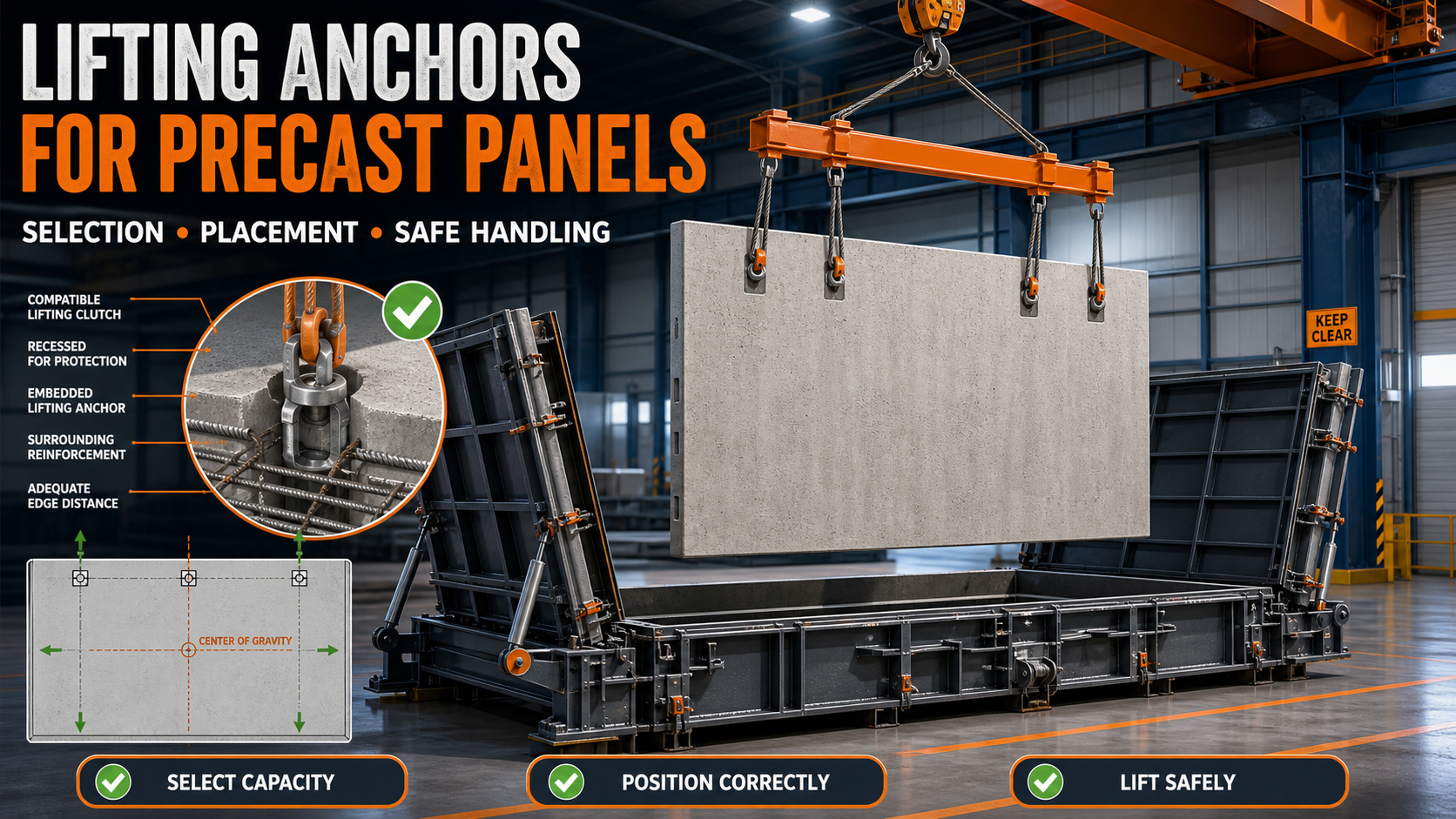
Lifting Anchors for Precast Panels: Selection, Placement and Safe Handling Guide
Lifting Anchors for Precast Panels: Selection, Placement and Safe Handling Guide
Lifting anchors allow precast concrete panels to be safely removed from heavy-duty iron moulds, shifted within the factory, loaded for transportation and installed at the project site.
Selecting an anchor only according to the panel’s total weight can be dangerous. The actual force applied to each anchor is affected by lifting direction, sling angle, load distribution, concrete strength, panel geometry, mould adhesion and dynamic handling forces.
Every lifting arrangement should be designed by a qualified person according to the approved panel drawing, applicable safety requirements and technical data supplied by the anchor-system manufacturer.
What Is a Precast Lifting Anchor?
A lifting anchor is a load-transfer component embedded inside a precast concrete product.
Compatible lifting hardware connects the anchor to a crane, lifting beam or other approved lifting system.
A complete lifting system may include:
• Embedded lifting anchor • Recess former • Lifting clutch • Lifting eye • Approved hook or shackle • Additional reinforcement • Sling or chain • Spreader or lifting beam • Crane or lifting equipment
All components must be compatible. Similar-looking components from different systems should not be combined unless the manufacturer has specifically approved their use together.
Common Types of Precast Lifting Anchors
Foot or Pin Anchors
These anchors transfer load into the concrete through their embedded shape and bearing area.
They may be used for lifting flat precast products when selected according to the manufacturer’s design data.
Erection Anchors
Erection anchors are commonly used where a panel must be lifted from a horizontal casting position and rotated into a vertical position.
The anchor and its reinforcement must be suitable for the changing load direction during rotation.
Plate Anchors
Plate anchors use an embedded plate or shaped end to transfer load into the surrounding concrete.
Their suitability depends on the panel thickness, edge distance, concrete strength and lifting direction.
Threaded Lifting Inserts
Threaded inserts receive compatible lifting loops, bolts or lifting devices.
The correct thread engagement and compatible hardware are essential. Dirty or damaged threads can reduce safety.
Utility Anchors
Utility anchor systems may be used for demoulding, factory handling, loading, unloading or installation when permitted by the manufacturer’s technical instructions.
The correct hook or shackle size must be used because oversized hardware may apply unintended forces.
Special Edge-Lifting Anchors
Thin panels or panels lifted from their edges may require anchors designed specifically for edge lifting.
Standard face-lifting anchors should not automatically be used for edge lifting.
Information Required Before Selecting an Anchor
Anchor selection should begin with complete lifting information.
Important details include:
• Panel length, width and thickness • Concrete volume • Estimated panel weight • Reinforcement arrangement • Concrete strength at first lift • Number of lifting anchors • Anchor locations • Centre of gravity • Initial casting position • Final lifting position • Lifting direction • Sling angle • Crane-hook position • Mould adhesion • Dynamic lifting effects • Edge distance • Anchor spacing • Openings and cut-outs • Transportation and erection method
If any of these conditions change, the lifting design should be reviewed.
How to Calculate Panel Weight
A preliminary panel weight may be estimated from:
Panel Weight = Concrete Volume × Concrete Density
Additional embedded components should also be considered where their weight is significant.
The final lifting design should use the project’s approved concrete density and actual panel geometry.
Openings may reduce concrete volume, but they can also shift the centre of gravity and change load distribution between anchors.
Why Total Panel Weight Is Not Enough
Dividing the panel weight equally by the number of anchors may produce an unsafe result.
The actual force on an individual anchor can increase due to:
• Unequal anchor positions • Offset centre of gravity • Unequal sling lengths • Small sling angle • Mould adhesion • Panel rotation • Sudden crane movement • Impact or dynamic loading • Incorrect lifting-beam arrangement • Uneven panel geometry • One anchor engaging before another
The lifting design must account for these effects according to the anchor manufacturer’s design method and applicable requirements.
Concrete Strength at the Time of Lifting
Anchor capacity depends heavily on the concrete strength when the load is applied.
A panel may appear hard while the concrete surrounding its lifting anchors remains too weak for safe lifting.
Before demoulding, confirm that the concrete has achieved the approved lifting strength through the project’s quality-control process.
Verification may include:
• Representative test specimens • Approved maturity monitoring • Recorded curing conditions • Approved early-strength test results • Quality-control clearance
The required lifting strength is not necessarily the same as the final design strength.
Anchor Capacity and Safe Working Load
Each lifting-anchor system has a stated working-load capacity for defined conditions.
The listed capacity may depend on:
• Anchor type • Anchor size • Embedment length • Concrete strength • Edge distance • Anchor spacing • Reinforcement arrangement • Load direction • Panel thickness • Lifting hardware • Installation accuracy
Do not select an anchor from its name or tonnage marking alone. Confirm that every installation condition satisfies the current manufacturer’s technical requirements.
Importance of Load Direction
An anchor can experience different types of loading during panel handling.
Tension Loading
The force acts mainly along the anchor’s intended tensile direction.
Shear Loading
The force acts across the anchor, which can occur during edge lifting or panel rotation.
Combined Loading
The anchor receives tension and shear simultaneously.
The anchor capacity may change with the load direction. Additional reinforcement or a special anchor may be required for shear and rotation.
Anchor Placement in a Precast Panel
Anchor positions should distribute the panel load as evenly as practical while controlling bending stresses.
The placement design should consider:
• Panel centre of gravity • Number of anchors • Panel dimensions • Openings • Edge distances • Anchor spacing • Reinforcement congestion • Lifting direction • Crane access • Storage orientation • Installation sequence
Anchors should not be moved on the production floor merely because they interfere with reinforcement or an insert. The conflict should be reviewed by the responsible technical team.
Centre of Gravity
The lifting points should be arranged in relation to the panel’s centre of gravity.
A panel with a large door or window opening may have an offset centre of gravity. Symmetrically placed anchors may therefore carry unequal loads.
The lifting design should use the actual panel geometry instead of assuming uniform weight distribution.
Edge Distance
Anchors positioned too close to a panel edge may cause concrete breakout or edge failure.
Minimum edge distance depends on the anchor system, embedment, concrete strength, load direction and reinforcement arrangement.
Follow the current technical data supplied by the selected anchor manufacturer.
Anchor-to-Anchor Spacing
Anchors placed too close together can have overlapping concrete failure zones.
The minimum permitted spacing should be checked against the manufacturer’s design information.
Panel Thickness
The selected anchor must fit inside the panel while maintaining the required concrete cover and clearance from the heavy-duty iron mould.
An anchor that is suitable for a thick panel may be unsuitable for a thin product.
Additional Anchor Reinforcement
Some lifting conditions require additional reinforcement around the anchor.
This may include:
• Tension reinforcement • Shear reinforcement • Hairpin bars • Edge reinforcement • Anchor-zone bars • Additional mesh • Reinforcement around openings
The reinforcement type, diameter, shape, orientation and position must follow the approved anchor detail.
Adding reinforcement without an engineered detail does not automatically increase anchor capacity.
Installing Anchors Inside an Iron Panel Mould
A typical installation process may include:
1. Clean and inspect the heavy-duty iron mould. 2. Confirm the approved panel and lifting drawings. 3. Mark anchor positions from fixed reference points. 4. Install the recess formers or anchor holders. 5. Position the reinforcement cage. 6. Install the lifting anchors at the specified depth. 7. Add the required anchor reinforcement. 8. Check concrete cover and edge distance. 9. Confirm anchor orientation. 10. Secure every anchor against movement. 11. Verify compatibility with the lifting clutch. 12. Complete the pre-pour inspection. 13. Record the inspection result. 14. Pour and vibrate concrete without disturbing the anchors.
Anchor holders should keep the components stable during concrete placement and vibration.
Pre-Pour Lifting-Anchor Inspection
Before pouring concrete, verify:
• Correct anchor system • Correct anchor capacity and size • Correct number of anchors • Correct anchor location • Correct embedment • Correct orientation • Required edge distance • Required anchor spacing • Additional reinforcement installed • Recess former secured • Reinforcement cage clearance • Insert conflicts resolved • Anchor identification visible where applicable • Approved drawing available
Any incorrect anchor should be repositioned before casting.
Anchor Movement During Concrete Casting
Fresh concrete flow and vibration can move an inadequately fixed anchor.
Movement may alter:
• Embedment depth • Anchor orientation • Edge distance • Recess position • Connection with reinforcement • Final lifting direction
Concrete should be placed carefully around anchor zones and fully compacted without directly striking or displacing the assembly.
Honeycombing around an anchor can seriously affect its load-transfer capacity.
Safe Demoulding From an Iron Mould
Before lifting a panel from its heavy-duty iron mould:
• Confirm the approved concrete lifting strength • Completely release all locks and shutters • Check that inserts and block-outs are free • Remove unintended mould restraints • Inspect each anchor recess • Clean the anchor head • Connect compatible lifting hardware • Position the crane correctly • Apply load gradually • Monitor panel separation • Keep personnel clear of the suspended load
The crane should not be used to force a panel out of a mould that is still locked or bonded.
Mould Adhesion
Concrete can adhere to an iron mould when the surface is dirty, damaged or inadequately coated with release agent.
Mould adhesion increases the force required for initial separation.
To reduce adhesion:
• Clean mould surfaces properly • Use a suitable release agent • Apply a thin and uniform coating • Repair damaged casting plates • Open shutters completely • Follow the designed demoulding sequence
Do not assume that anchor capacity only needs to support the panel’s dead weight during initial demoulding.
Sling Angle and Anchor Load
When inclined slings are used, horizontal force components are created and the load on each lifting point can increase.
A lifting beam can help maintain a more favourable lifting direction and distribute loads according to the approved lifting design.
The sling angle, lifting-beam arrangement and crane-hook position should be established before lifting begins.
Do not estimate anchor load visually at the production floor.
Panel Rotation and Tilting
A horizontally cast panel may need to rotate into a vertical position.
During rotation:
• The load direction changes • Edge forces may increase • Different anchors may carry different loads • Concrete corners may contact supports • The crane geometry changes • Shear reinforcement may become critical
The anchor system must be suitable for the complete rotation sequence, not only the final vertical lift.
Lifting Hardware Inspection
Before every lift, inspect:
• Lifting clutches • Chains • Slings • Shackles • Hooks • Lifting beams • Crane hook • Connecting pins • Identification markings • Signs of wear or deformation
Damaged, modified or unidentified hardware should be removed from service and evaluated according to the applicable inspection procedure.
Compatible Lifting Components
Use only lifting hardware approved for the selected anchor system.
Incorrect clutches, hooks or shackles may not seat properly and can apply unintended loads to the anchor.
Never modify a lifting clutch or anchor at the factory to make incompatible components fit.
Safe Handling Rules
During panel lifting:
• Use an approved lifting plan • Use trained and authorised personnel • Confirm crane and rigging capacity • Establish an exclusion zone • Keep personnel clear of suspended loads • Use tag lines where appropriate • Avoid sudden crane movement • Prevent shock loading • Do not drag the panel • Do not use damaged anchors • Do not lift before strength approval • Do not exceed the approved load • Store the panel on suitable supports
Local laws and project safety requirements must also be followed.
Common Lifting-Anchor Mistakes
Selecting Anchors Only by Panel Weight
Actual anchor load also depends on sling angle, adhesion, load distribution and dynamic effects.
Placing Anchors Too Close to an Edge
Insufficient edge distance can cause concrete breakout.
Using Incompatible Hardware
A lifting clutch that appears to fit may still be unsafe if it is not approved for the anchor.
Lifting Concrete Too Early
The anchor may be strong, but weak surrounding concrete can fail.
Incorrect Anchor Orientation
An anchor positioned in the wrong direction may not resist the intended lifting force.
Missing Additional Reinforcement
Some anchors require specific reinforcement to achieve their rated capacity.
Poor Concrete Compaction
Honeycombing around an anchor reduces reliable load transfer.
Moving Anchors Without Approval
Changing an anchor location affects load distribution and panel stresses.
Standing Under a Suspended Panel
No person should remain beneath a suspended precast panel.
Reusing Damaged Lifting Hardware
Worn or deformed lifting accessories can fail even when the embedded anchor is undamaged.
Post-Demoulding Inspection
After demoulding, check:
• Concrete around every anchor • Cracks near lifting points • Edge damage • Honeycombing • Anchor recess condition • Panel dimensions • Lifting-hardware marks • Permanent deformation • Product identification
A panel with damage around an anchor should not be lifted again until it has been assessed and approved.
Lifting Plan Checklist
Product Information:
• Panel identification confirmed • Panel weight verified • Centre of gravity determined • Concrete strength approved • Openings and inserts checked
Anchor System:
• Anchor type verified • Anchor capacity verified • Embedment checked • Edge distance checked • Anchor spacing checked • Reinforcement detail checked • Load direction confirmed
Lifting Equipment:
• Crane capacity confirmed • Lifting beam selected • Slings inspected • Lifting clutches inspected • Hardware compatibility confirmed • Sling angle checked
Work Area:
• Mould completely released • Lifting path clear • Exclusion zone established • Storage supports prepared • Communication method agreed • Trained personnel assigned
Final Conclusion
Safe precast panel handling begins with an engineered lifting arrangement.
Anchor selection must consider panel weight, concrete strength, anchor spacing, edge distance, load direction, sling angle, mould adhesion and dynamic forces.
Every anchor should be installed according to the approved drawing and current technical instructions supplied by the anchor-system manufacturer.
The panel should be lifted only after achieving the approved concrete strength and after the heavy-duty iron mould has been fully released.
Paras Steel Industries manufactures customised heavy-duty iron precast panel moulds with suitable anchor-position arrangements, insert holders, structural stiffeners and opening systems according to customer drawings and production requirements.
For customised mould specifications, share your precast panel drawing, panel dimensions, reinforcement details, lifting-anchor arrangement and daily production target with Paras Steel Industries.
Safety Note:
This article provides general production guidance. Lifting-anchor selection, capacity calculation, placement, reinforcement, rigging and lifting procedures must be approved by qualified professionals according to the selected anchor manufacturer’s current technical data and applicable local regulations.