
Precast Infrastructure Moulds
L-Shape Retaining Wall Mould: Heel, Toe, Stem Alignment and Monolithic Casting Guide
An L-shape retaining wall mould casts the vertical stem and horizontal foundation base as one monolithic concrete unit. This guide explains heel, toe and stem alignment, reinforcement, casting, demoulding and quality checks.
By Paras Steel Industries ·
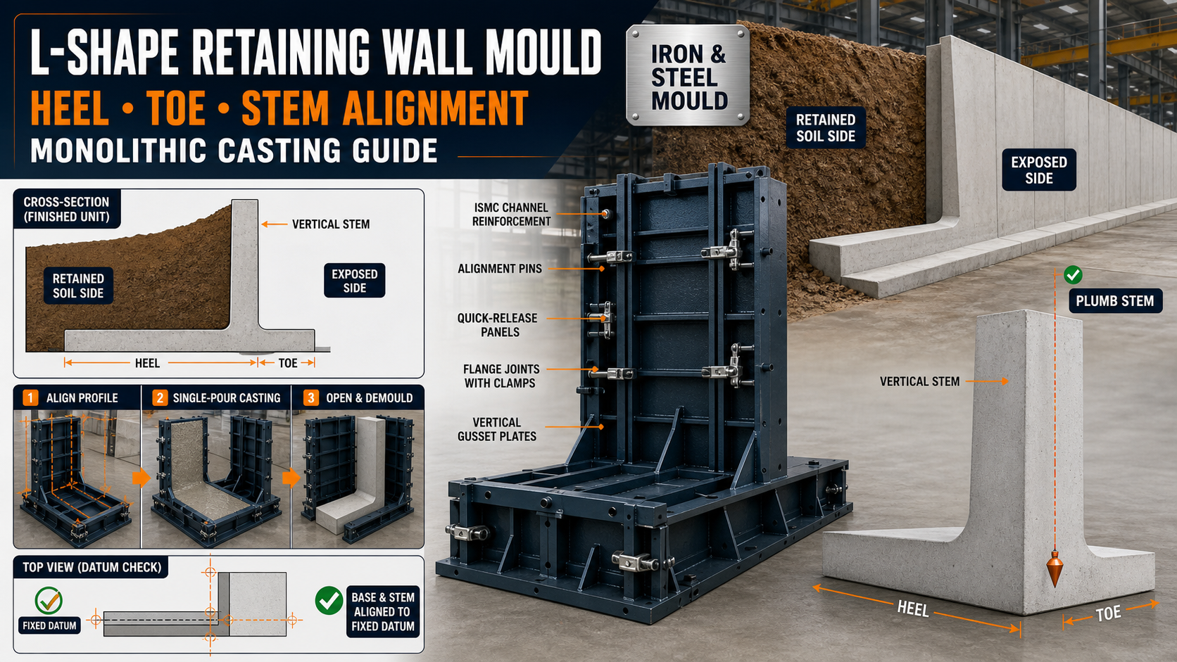
L-Shape Retaining Wall Mould: Heel, Toe, Stem Alignment and Monolithic Casting Guide
L-Shape Retaining Wall Mould: Heel, Toe, Stem Alignment and Monolithic Casting Guide
Precast L-shape retaining walls are used to retain soil and create level differences in highway, industrial, landscaping and infrastructure projects.
An L-shaped unit combines a vertical wall stem with a horizontal base. Depending on the approved design and installation direction, the base may include a heel, a toe or a project-specific combination of both.
The connection between the stem and base must be cast accurately because it transfers structural forces through the complete retaining-wall unit.
A heavy-duty iron and steel mould allows the stem and base to be manufactured in one continuous concrete pour. This monolithic process eliminates a separate casting joint between the two primary components.
Paras Steel Industries manufactures IS 2062 steel L-shape retaining wall moulds with reinforced shutters, structural channels, gusset plates, slurry-tight joints and quick-release panels.
What Is an L-Shape Retaining Wall?
An L-shape retaining wall is a precast concrete unit consisting of:
• A vertical stem • A horizontal foundation base • A monolithic stem-to-base junction • Structural reinforcement • Lifting and handling provisions • Project-specific connection details
The vertical stem retains the soil or other backfill. The base transfers loads to the supporting foundation.
The final geometry must follow an approved structural drawing prepared for the project’s soil conditions, retained height, surcharge, drainage and installation requirements.
Understanding the Stem
The stem is the upright section of the retaining wall.
Important stem dimensions include:
• Overall height • Top thickness • Bottom thickness • Face taper • Vertical alignment • Base-junction thickness • Reinforcement position • Lifting-point location
The stem may have a constant thickness or a designed taper. The mould shutters must reproduce this profile accurately.
A leaning or twisted stem can create installation gaps and affect the alignment of adjoining retaining-wall units.
What Is the Heel?
The heel is generally the portion of the base located beneath the retained soil or backfill.
Its dimensions depend on the structural design and wall orientation.
The mould must accurately form:
• Heel length • Heel thickness • Stem-to-heel junction • Reinforcement cover • External edges • Required taper or slope • Project-specific recesses
The heel should not be identified only from the visual appearance of an isolated precast unit. Its name depends on the installed wall orientation and retained-soil side.
What Is the Toe?
The toe is generally the portion of the base extending toward the exposed side of the retaining wall.
The approved design may contain a pronounced toe, a short toe or another base arrangement depending on structural requirements.
Important details include:
• Toe projection • Toe thickness • Concrete cover • Stem position • Reinforcement • External edge geometry • Required installation clearance
The mould must follow the project drawing rather than use assumed heel and toe dimensions.
Heel vs Toe: Why Orientation Matters
Heel and toe terminology depends on the wall’s installed direction.
Before mould fabrication, confirm:
• Retained-soil side • Exposed face • Stem position on the base • Heel projection • Toe projection • Installation direction • Architectural face • Lifting orientation • Drainage arrangement
Incorrectly interpreting the drawing can produce a mirrored unit that does not match the site requirement.
What Is Monolithic Casting?
Monolithic casting means producing the stem and horizontal base in one continuous concrete pour.
This creates a single precast unit without a separate construction joint between the stem and footing base.
Possible benefits include:
• Integrated stem-to-base junction • Consistent product geometry • Reduced site formwork • Faster site installation • Factory-controlled concrete production • Accurate reinforcement positioning • Repeatable wall dimensions • Reduced dependence on site casting
Structural performance still depends on the approved design, reinforcement, concrete strength, curing and installation.
Main Components of an L-Shape Retaining Wall Mould
A heavy-duty mould may contain:
• IS 2062 iron or steel base plate • Stem face shutters • Base and heel/toe shutters • Removable end plates • Heavy ISMC channel framework • Vertical gusset plates • Angle stiffeners • Quick-release bolts or clamps • Slurry-tight flange joints • Alignment pins • Tapered demoulding profiles • Lifting and handling points • Reinforcement-positioning fixtures
The exact mould construction depends on the unit dimensions, concrete pressure and operating arrangement.
Importance of Stem Alignment
The stem must remain at the specified position and angle relative to the base.
Incorrect alignment may cause:
• Leaning wall units • Uneven joints during installation • Variable heel or toe dimensions • Difficulty maintaining wall line • Incorrect architectural face • Unequal stem thickness • Problems during lifting and storage
The mould frame requires strong channels and gusset plates to prevent the vertical shutters from moving under concrete pressure and vibration.
Stem Alignment Checks
Verticality
Use a suitable level or plumb-checking method to verify the stem shutter.
Centreline or Offset
Measure the stem position from fixed base reference points.
Stem Thickness
Check the distance between face shutters at the bottom, middle and top.
Straightness
Use a straightedge or string line across the full shutter length.
End Alignment
Confirm that both end plates are square to the stem shutters.
Face Taper
Where the approved drawing specifies taper, verify it using suitable templates or measurements.
Heel and Toe Alignment Checks
Before casting, verify:
• Overall base length • Heel projection • Toe projection • Base width • Base thickness • Stem position • Diagonal measurements • End-face squareness • Reinforcement clearance • Shutter locking
All measurements should be taken from fixed datum points on the mould.
Do not rely only on temporary shutter edges because their positions can change during setup.
Stem-to-Base Junction
The junction between the stem and horizontal base is a critical part of the mould and finished product.
The area may contain:
• Dense reinforcement • Designed internal radius or chamfer • Increased stem thickness • Project-specific haunch • Lifting reinforcement • Limited space for concrete flow
The mould should provide sufficient access for concrete placement and compaction.
Any radius, chamfer or haunch must follow the approved structural drawing.
Reinforcement Placement
The reinforcement cage should be prepared according to the approved design.
Important checks include:
• Base reinforcement • Stem reinforcement • Starter bars through the junction • Heel and toe reinforcement • Bar spacing • Concrete cover • Anchorage length • Lapping and connection details • Lifting-anchor reinforcement • Spacer position • Clearance from mould shutters
The reinforcement should remain stable during concrete filling and vibration.
Mould Setup Process
A typical setup process includes:
1. Clean the complete iron or steel mould. 2. Inspect base and stem shutters. 3. Remove concrete residue from flange joints. 4. Position the base shutters. 5. Set the heel and toe arrangement. 6. Install and align the stem shutters. 7. Position both end plates. 8. Engage alignment pins. 9. Check verticality and straightness. 10. Measure heel, toe and stem positions. 11. Check diagonals and end squareness. 12. Tighten all clamps and bolts uniformly. 13. Apply a suitable mould-release agent. 14. Position and secure the reinforcement cage. 15. Install approved lifting components. 16. Complete the final dimensional inspection.
The mould should be rechecked after locking because tightening may change its alignment.
Balanced Concrete Placement
Fresh concrete creates considerable pressure on tall stem shutters.
Concrete should be placed in a controlled and balanced sequence to prevent:
• Shutter movement • Stem bulging • Reinforcement displacement • Insert movement • Uneven compaction • Excessive pressure at one location
Avoid filling the complete stem height from one point too quickly.
The pouring sequence should be planned according to the wall dimensions, concrete properties and mould design.
Concrete Compaction
Correct compaction is necessary around the stem-to-base junction and dense reinforcement.
Suitable vibration may be provided through:
• External shutter vibrators • Internal vibration where permitted • Project-specific compaction systems
Inspect areas around:
• Base corners • Heel and toe edges • Stem junction • Lifting components • Dense reinforcement • End shutters
Insufficient vibration can produce honeycombing. Excessive vibration can cause segregation or increase the risk of shutter leakage.
Preventing Mould Bulging
The vertical stem shutter is exposed to concrete pressure during casting.
Bulging can be controlled through:
• Correct steel-plate selection • Heavy ISMC channel reinforcement • Vertical gusset plates • Uniform stiffener spacing • Strong tie arrangements • Proper locking • Controlled pour rate • Regular dimensional inspections
A visibly bent shutter should be repaired before the next casting cycle.
Slurry-Tight Joint System
Cement slurry can escape through the junction between shutters.
Leakage may cause:
• Honeycombing • Damaged edges • Concrete fins • Weak surface zones • Material loss • Difficult finishing • Dimensional variation
Before casting:
• Clean flange surfaces. • Inspect joint contact. • Repair damaged edges. • Tighten bolts uniformly. • Install the specified sealing arrangement. • Check end-plate joints. • Inspect the stem-to-base connection.
Demoulding Process
Demoulding should begin only after the concrete has achieved sufficient handling strength.
A typical process includes:
1. Confirm the required concrete strength. 2. Clear the working area. 3. Remove end-plate connections. 4. Release the external locking system. 5. Open the stem shutters gradually. 6. Release base and heel/toe shutters. 7. Maintain support for the concrete unit. 8. Avoid uncontrolled hammering. 9. Lift using approved embedded anchors. 10. Move the unit to prepared storage supports. 11. Inspect the stem, base and edges.
Calculated draft angles and quick-release panels can make the demoulding process easier.
Lifting and Handling
An L-shape retaining wall has an uneven geometry and centre of gravity.
The lifting design must be prepared for the specific unit.
Before lifting:
• Confirm concrete handling strength. • Inspect lifting anchors. • Use the approved lifting arrangement. • Check sling angles. • Clear personnel from the lifting zone. • Keep the unit balanced. • Avoid impact with mould shutters. • Use suitable storage supports.
Never stand beneath a suspended precast unit.
Common Production Problems
Leaning Stem
Possible causes include incorrect shutter setup, loose bracing or unbalanced concrete pressure.
Incorrect Heel or Toe Length
This may result from reversed orientation, misplaced end shutters or incorrect datum measurements.
Stem Bulging
Insufficient stiffening, loose locks or an uncontrolled pour rate may deform the shutter.
Honeycombing at the Junction
Dense reinforcement, poor concrete flow or inadequate vibration can create voids.
Broken Base Edges
Premature demoulding, inadequate release agent or improper lifting may damage the edges.
Slurry Leakage
Damaged flange joints or uneven locking can allow cement paste to escape.
Twisted Unit
An uneven mould foundation, incorrect shutter alignment or poor storage support can cause distortion.
Quality-Control Checklist
After demoulding, inspect:
• Overall wall height • Stem verticality • Stem straightness • Stem thickness • Base length and width • Heel projection • Toe projection • Stem position on the base • End-face squareness • Diagonal dimensions • Concrete cover • Lifting-anchor position • Stem-to-base junction • Honeycombing • Cracks and damaged edges • Concrete strength • Surface finish
A profile template can help check repeat production.
Mould Cleaning and Maintenance
After every casting cycle:
• Remove concrete residue. • Clean flange and seal joints. • Inspect stem shutters for bending. • Check base shutters. • Examine gusset plates and channels. • Inspect clamps, bolts and alignment pins. • Lubricate approved moving parts. • Repair slurry-leakage areas. • Check lifting points on the mould. • Verify stem verticality periodically. • Inspect anti-rust coating. • Store removable panels correctly.
Regular maintenance preserves the dimensional accuracy of the finished retaining-wall units.
Factors to Check Before Buying
Before ordering an L-shape retaining wall mould, provide:
• Approved structural drawing • Overall unit height • Stem thickness and taper • Base dimensions • Heel projection • Toe projection • Retained-soil orientation • Stem position • Haunch or radius details • Reinforcement drawing • Lifting-anchor details • Required number of moulds • Expected daily production • Concrete pouring method • Vibration arrangement • Crane and handling capacity • Required dimensional tolerance
The buyer should also discuss iron or steel plate thickness, ISMC channel reinforcement, gusset spacing, opening system and slurry-sealing arrangement.
Conclusion
An L-shape retaining wall mould must maintain accurate heel, toe and stem geometry throughout concrete pouring, vibration and demoulding.
Fixed datum measurements, strong stem-shutter reinforcement and correct orientation checks help prevent mirrored units, leaning stems and inconsistent base dimensions. Monolithic casting produces the vertical stem and horizontal base as one integrated precast component.
Paras Steel Industries manufactures heavy-duty IS 2062 iron and steel L-shape retaining wall moulds with reinforced channels, gusset plates, quick-release panels and slurry-tight joints. Complete structural, reinforcement and lifting drawings should be provided before mould manufacturing begins.