
Precast Infrastructure Moulds
L-Shape Retaining Wall Mould End-Shutter Alignment: Unit Length, Stem Profile and Joint Sealing
The end shutters of an L-shape retaining wall mould control the finished unit length and close the heel, toe and stem profiles. Incorrect alignment, dirty contact faces or uneven locking can create dimensional variation, slurry leakage and damaged concrete edges. This guide explains end-shutter setup, sealing and inspection.
By Paras Steel Industries ·
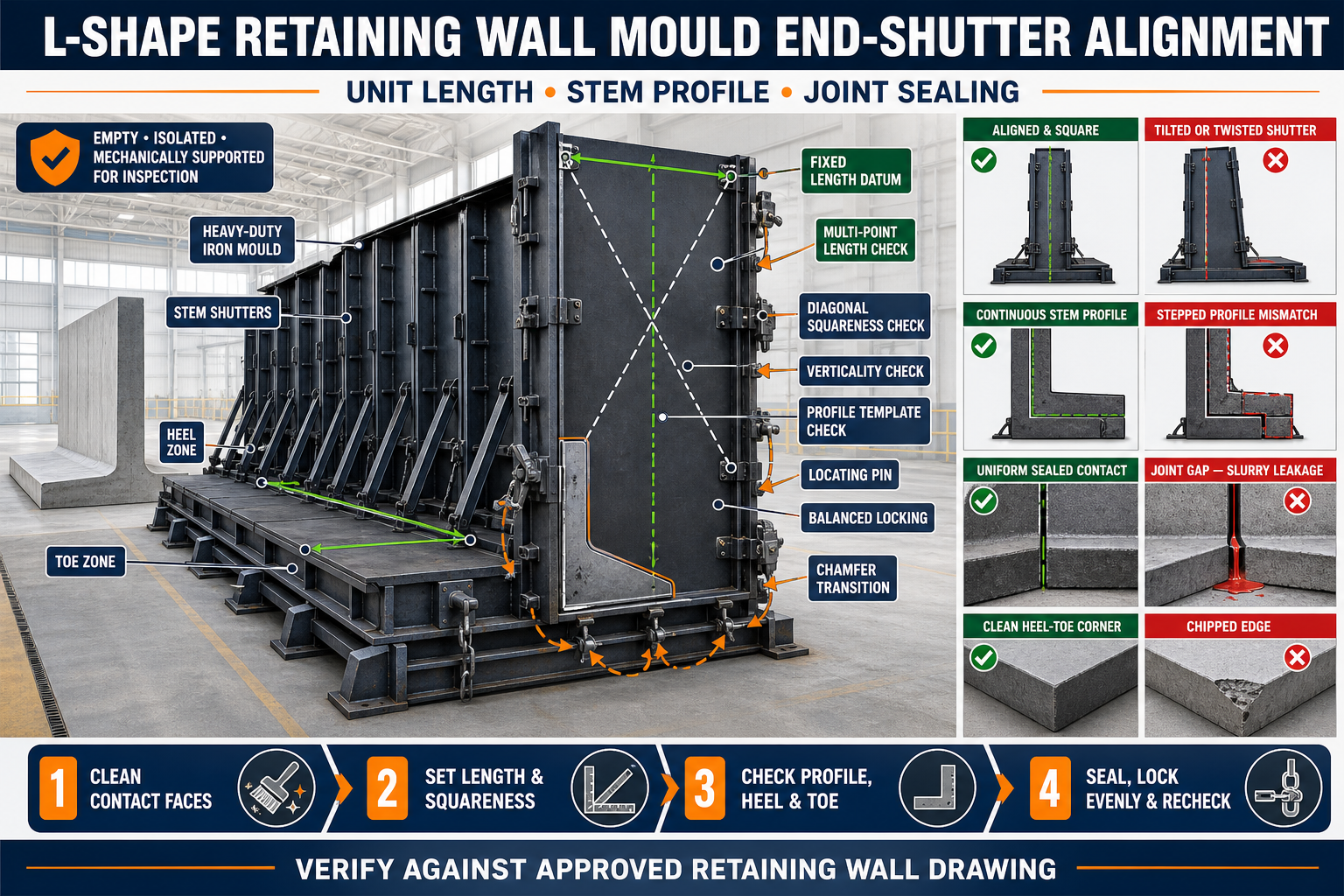
L-Shape Retaining Wall Mould End-Shutter Alignment: Unit Length, Stem Profile and Joint Sealing
L-Shape Retaining Wall Mould End-Shutter Alignment: Unit Length, Stem Profile and Joint Sealing
An L-shape retaining wall mould produces a monolithic precast concrete unit consisting of a vertical stem and horizontal base.
The base may include a heel, toe or another project-specific configuration. End shutters close the mould cavity and form the two end faces of the retaining wall unit.
Their position affects the finished unit length, stem profile, base geometry, corner transitions and slurry sealing. A misaligned or distorted end shutter can therefore affect the complete precast component.
What Is an L-Shape Retaining Wall Mould?
An L-shape retaining wall mould is a heavy-duty iron or steel form used to cast the vertical stem and foundation base in one concrete pour.
A typical mould may include:
• Steel mould bed • Stem-forming shutters • Heel and toe forming plates • End shutters • Structural stiffeners • Hinges • Locating pins • Quick locks or clamps • Tie rods • Chamfer strips • Joint seals • Reinforcement-positioning fixtures • Mechanical or hydraulic opening systems
The exact mould geometry should match the approved retaining wall drawing.
What Is an End Shutter?
An end shutter is the removable or hinged steel plate installed at the end of the casting cavity.
It may form:
• Stem end face • Heel end face • Toe end face • Base-slab end • Chamfer transitions • Connection recesses • Project-specific joint details
The shutter should contact all adjoining mould surfaces correctly.
Functions of the End Shutter
A correctly installed end shutter helps:
• Establish unit length • Maintain a square end face • Complete the L-shaped profile • Close the stem cavity • Close the heel and toe cavities • Prevent slurry leakage • Support end-detail inserts • Maintain dimensional consistency • Produce cleaner concrete edges • Support repeatable production
Every part of the shutter should remain stable during concrete placement and vibration.
Why End-Shutter Accuracy Is Important
Incorrect setup can produce:
• Variable retaining-wall length • Tilted end faces • Incorrect stem dimensions • Uneven heel or toe length • Slurry leakage • Concrete fins • Honeycombing • Broken corners • Difficult demoulding • Mismatched adjoining units • Increased grinding and repair
A small gap at a complex L-profile transition can create a significant finish defect.
Understanding Unit Length
Unit length is the approved distance between the two end-forming surfaces.
Length should be checked at:
• Stem top • Stem bottom • Heel edge • Toe edge • Base centreline • Corresponding positions on both sides
A single measurement cannot detect a tilted or skewed end shutter.
What Is the Stem Profile?
The stem is the vertical part of the retaining wall unit.
Its mould profile may include:
• Vertical or specified sloping face • Controlled thickness • Taper • Chamfered edges • Connection details • Architectural finish • Project-specific geometry
The end shutter should follow the complete stem profile without creating a step or gap.
Heel and Toe Geometry
The base of an L-shape retaining wall may extend on one or both sides of the stem according to the engineered design.
Heel and toe dimensions must come from the approved drawing.
End-shutter setup should check:
• Heel length at the end • Toe length at the end • Base-slab width • Stem position on the base • Corner transitions • Base thickness • End-face squareness
Do not assume that every L-shape retaining wall has the same heel and toe arrangement.
Common End-Shutter Alignment Problems
Typical problems include:
• Shutter tilted inward • Shutter tilted outward • Shutter shifted longitudinally • Stem-profile mismatch • Heel or toe section not fully closed • End face out of square • Shutter twisted • Local joint gaps • Uneven locking • Incorrect end-detail insert position
These conditions should be corrected before casting.
Causes of End-Shutter Misalignment
Misalignment may result from:
• Hardened concrete on contact faces • Worn locating pins • Bent guide components • Damaged hinge pins • Uneven lock adjustment • Distorted shutter plate • Cracked welds • Loose stiffeners • Impact during handling • Base-mould movement • Incorrect end-stop position • Reinforcement interference • Previous repair distortion • Excessive vibration • Foundation settlement
The entire mould should be inspected rather than adjusting only one lock.
Preparing the Mould for Inspection
Before setup or measurement:
• Empty and clean the mould • Remove hardened concrete • Isolate hydraulic equipment • Release stored pressure • Mechanically support movable shutters • Secure stem-forming components • Clean locating points • Inspect the mould foundation • Review the approved product drawing • Identify fixed reference datums • Prepare suitable measuring tools
Never work near an unsupported end shutter.
Identifying the Correct End Shutter
The two end shutters may contain different details.
Confirm:
• Left or right identification • Casting direction • Stem profile • Heel and toe orientation • Connection details • Chamfer positions • Insert locations • Project identification • Compatibility with the mould size
Clearly marking each shutter reduces setup mistakes.
Establishing a Fixed Datum
End-shutter position should be checked from verified mould references.
Possible datums include:
• Mould-bed centreline • Fixed base-frame edge • Approved end stop • Machined reference face • Stem centreline • Foundation survey mark • Opposite verified end shutter
Do not measure from a damaged or unverified movable component.
Checking Unit Length
A general procedure may include:
1. Clean Both End-Forming Surfaces
Remove all buildup.
2. Close the End Shutters Lightly
Engage locating pins without applying full force.
3. Verify the Fixed Datum
Confirm the reference before measurement.
4. Measure Stem-Top Length
Check between corresponding points.
5. Measure Stem-Bottom Length
Compare with the upper measurement.
6. Measure Heel and Toe Lengths
Use matching reference points.
7. Check Both Sides
Identify shutter tilt or skew.
8. Tighten Progressively
Apply balanced locking.
9. Repeat the Measurements
Confirm the shutter did not move.
10. Record the Results
Compare with the approved drawing.
No generic unit length or tolerance should be assumed.
Checking End-Face Squareness
A square end face helps adjoining units align correctly.
Possible inspection methods include:
• Approved engineer’s square • Diagonal measurements • Laser alignment • Survey equipment • Profile template • Upper and lower length comparison
The end shutter should be checked relative to both the stem and base.
Checking End-Shutter Verticality
The end shutter may need to remain vertical or follow another specified orientation.
Check:
• Front-to-back plumb • Side-to-side position • Top-to-bottom displacement • Relationship with the mould bed • Alignment after final locking
Use the approved product drawing as the reference.
Checking End-Shutter Twist
A twisted shutter may contact one corner while leaving another corner open.
Twist may be identified through:
• Diagonal measurements • Corner contact checks • Laser reference plane • Straightedge inspection • Comparison of opposite edges • Uneven lock engagement
Do not force a twisted plate closed with excessive clamping pressure.
Checking Stem-Profile Continuity
The end shutter should meet the stem-forming shutters without a step.
Inspect:
• Stem thickness • Taper where specified • Top edge • Lower stem transition • Chamfer strips • Architectural liner transitions • Joint details • Side-shutter contact
Use an approved profile template where suitable.
Checking Heel and Toe Transitions
The end shutter should close the complete base profile.
Inspect:
• Heel corner • Toe corner • Stem-to-base junction • Base underside • Chamfer transitions • Joint-sealing surfaces • Reinforcement clearance
Complex corners are common locations for slurry leakage.
Using a Profile Template
A verified template can help check:
• L-profile geometry • Stem shape • Heel and toe transitions • Chamfer continuity • End-face profile • Correct shutter identity
The template should be protected from wear and checked periodically.
Inspecting Contact Faces
Clean mating surfaces are essential for alignment and sealing.
Inspect for:
• Hardened slurry • Concrete particles • Rust flakes • Dents • Scratches • Weld spatter • Seal residue • Bent edges • Previous grinding • Local high points
A thin concrete deposit can create a visible gap elsewhere.
Understanding Joint Gaps
A joint gap is the clearance between the end shutter and adjoining mould component.
Gaps may occur at:
• Stem side shutter • Mould bed • Heel plate • Toe plate • Chamfer strip • Profile insert • Connection former • Corner transition
Every gap below the concrete level can become a leakage path.
Causes of Slurry Leakage
Leakage may result from:
• Dirty contact faces • Bent end shutter • Damaged seal • Uneven locking • Worn locating pins • Stem-shutter misalignment • Base-mould distortion • Cracked weld • Incorrect profile insert • Reinforcement trapped in a joint • Excessive vibration • Concrete buildup
Adding excessive sealing material will not correct mechanical misalignment.
Joint-Sealing Methods
Depending on the mould design, sealing may use:
• Accurate steel-to-steel contact • Replaceable sealing strip • Approved mould gasket • Profile-specific seal • Suitable compressible sealing component
The seal should not change the required unit dimensions.
Installing a Sealing Strip
A general procedure may include:
• Clean the sealing groove • Remove old material • Inspect the groove • Select the approved seal • Install without stretching • Maintain continuity at corners • Avoid unapproved overlap • Close the shutter gently • Check even compression • Reinspect after locking
Replace seals that are cut, flattened, hardened or displaced.
Inspecting Locating Pins and Stops
Locating components establish repeatable shutter position.
Check for:
• Bent pins • Worn bushes • Enlarged holes • Loose stops • Concrete buildup • Cracked mounting welds • Incomplete seating • Unequal contact • Impact damage • Corrosion
Worn locating points can produce different unit lengths between casting cycles.
Inspecting Hinges
Where the shutter is hinged, inspect:
• Hinge-pin wear • Bush condition • Hinge-leaf alignment • Mounting bolts • Welds • Lubrication • Shutter sag • Binding • Opening path • Mechanical support
A sagging hinge can create different upper and lower joint gaps.
Inspecting Locks and Clamps
End shutters may use:
• Wedge locks • Screw clamps • Toggle clamps • Pin locks • Bolted flanges • Hydraulic locking • Combined systems
Inspect every lock for wear, alignment and secure mounting.
Balanced Locking Sequence
A general sequence may include:
1. Seat the Shutter on Locators
Confirm pins and stops are engaged.
2. Apply Central Locks Lightly
Hold the shutter without distorting it.
3. Engage Upper and Lower Locks
Do not fully tighten one corner.
4. Inspect Contact Around the L-Profile
Check stem, heel and toe joints.
5. Tighten Progressively
Use a balanced pattern.
6. Check Seal Compression
Confirm it remains uniform.
7. Recheck Length and Squareness
Ensure locking did not move the shutter.
8. Complete the Final Inspection
Verify every lock before casting.
Excessive force at one lock may open another joint.
Inspecting End-Shutter Stiffeners
Structural stiffeners help the shutter resist fresh concrete pressure.
Check for:
• Bent channels • Cracked welds • Local plate bulging • Loose brackets • Corrosion • Previous repair distortion • Damaged lock mounts • Separation from the face plate
A distorted shutter may require approved structural repair.
Connection and Insert Details
Some retaining wall units may include project-specific:
• Lifting inserts • Connection recesses • Dowel holes • Alignment keys • Bolt pockets • Joint formers • Identification recesses
These details should be positioned using approved jigs and drawings.
Reinforcement Clearance
The reinforcement cage should not prevent the end shutter from closing.
Check:
• Stem reinforcement • Base reinforcement • Heel and toe bars • Corner bars • Required concrete cover • Spacers • End-zone reinforcement • Insert reinforcement • Tie-wire clearance
Do not move or cut reinforcement without approval.
Applying Mould Release Agent
After cleaning and alignment, apply a suitable release agent.
The application should be:
• Thin • Uniform • Applied across the forming face • Present around corners and chamfers • Free from excessive pooling • Kept away from reinforcement • Compatible with the required finish
Release agent cannot seal a mechanical gap.
Pre-Pour End-Shutter Checklist
Before placing concrete, confirm:
• Correct end shutter is selected • Casting direction is correct • Mould surfaces are clean • Unit length is verified • End face is square • Shutter orientation is correct • Stem profile is continuous • Heel and toe transitions are aligned • Locating pins are seated • Hinges are stable • Locks are progressively tightened • Joint gaps are controlled • Seals are correctly installed • Reinforcement has adequate clearance • Inserts are positioned correctly • Release agent is uniformly applied • No tools remain inside the mould
Record the inspection according to the quality plan.
Concrete Placement Near the End Shutter
Concrete should be placed evenly around the L-shaped cavity.
Good practices include:
• Fill heel and toe areas carefully • Avoid direct impact on the end shutter • Maintain reinforcement position • Monitor stem filling • Prevent aggregate bridging • Watch all end-shutter joints • Keep locks visible where possible • Follow the approved placement sequence
Uneven filling can create unbalanced pressure.
Effect of Vibration
Vibration can increase leakage or move an inadequately secured shutter.
Before vibration:
• Check every lock • Confirm locating pins • Inspect seals • Verify mould supports • Remove loose tools
During vibration, observe for:
• Slurry leakage • Lock movement • Shutter vibration • Growing joint gaps • Local plate bulging • Unusual metallic noise
Stop the process safely if significant movement occurs.
Preparing for Demoulding
Before opening the mould:
• Confirm adequate concrete strength • Support the retaining wall unit • Isolate hydraulic equipment • Release stored pressure • Mechanically support shutters • Clean concrete around locks • Identify the approved opening sequence • Keep personnel clear of pinch points • Prepare suitable lifting equipment
The lifting arrangement should follow the engineered handling procedure.
Correct End-Shutter Demoulding Sequence
A general sequence may include:
1. Support the Concrete Unit
Prevent unexpected movement.
2. Remove External Slurry
Clean locks and shutter joints.
3. Release Secondary Locks
Open them progressively.
4. Support the Heavy End Shutter
Prevent it from dropping or swinging.
5. Release Primary Locks
Follow the approved sequence.
6. Create Controlled Separation
Use the designed opening mechanism.
7. Move the Shutter Along Its Approved Path
Avoid dragging it across concrete edges.
8. Protect Stem, Heel and Toe Corners
Keep steel components clear of fresh concrete.
9. Inspect the Finished End Face
Check profile, finish and dimensions.
Do not use uncontrolled hammering against the concrete.
Preventing Edge Damage
Concrete edges may break because of:
• Insufficient demoulding strength • Missing release agent • Concrete fins • Damaged chamfer strip • Shutter opened at an angle • Locks not fully released • Unit inadequately supported • Shutter distortion • Incorrect opening sequence
Repeated damage at the same corner should be traced to the mould.
Post-Demoulding Inspection
Inspect the finished retaining wall unit for:
• Unit length • End-face squareness • Stem profile • Heel and toe geometry • Base dimensions • Chamfer continuity • Joint details • Concrete fins • Chips • Cracks • Honeycombing • Surface finish • Compliance with the approved drawing
Record defects according to shutter location.
Troubleshooting Common Problems
Problem: Unit Length Is Different at the Top and Bottom
Possible causes:
• End shutter is tilted • Hinge has sagged • Locks are uneven • Opposite shutter is misaligned • Contact faces contain buildup
Problem: Slurry Leaks at the Stem-to-Base Corner
Possible causes:
• Local joint gap • Damaged corner seal • Chamfer-strip mismatch • Concrete buildup • Bent shutter transition • Weak lock
Problem: Concrete Fin Runs Around the End Profile
Possible causes:
• Continuous shutter gap • Seal is worn • Shutter is distorted • Locating pins are loose • Locks do not apply uniform pressure
Problem: Heel or Toe End Is Out of Square
Possible causes:
• End shutter is twisted • Base mould is misaligned • Incorrect profile insert is installed • Locking sequence is unbalanced • Mould bed has moved
Problem: End Shutter Is Difficult to Open
Possible causes:
• Concrete bonded to the shutter • Locks remain engaged • Concrete fin has trapped the joint • Hinge is binding • Shutter is distorted • Connection former has created interference
Problem: End Detail Is Incorrectly Positioned
Possible causes:
• Wrong jig was used • Insert moved during casting • Reference datum was incorrect • Reinforcement displaced the former • Fixture was loose
Correcting End-Shutter Alignment
A controlled correction may include:
• Cleaning contact surfaces • Replacing worn pins and bushes • Adjusting approved stops • Repairing hinges • Replacing damaged seals • Correcting shutter straightness • Repairing stiffeners • Realigning the mould base • Checking the foundation • Repeating length and profile inspection
Do not rely on excessive clamping force to correct structural distortion.
End-Shutter Maintenance Checklist
After every production cycle:
• Clean the forming face • Remove slurry from joints • Clean heel and toe transitions • Inspect chamfer strips • Check locating pins • Inspect hinges and bushes • Check locks and clamps • Inspect seals • Examine welds and stiffeners • Check plate straightness • Verify end-profile templates • Lubricate approved moving points • Apply corrosion protection during storage • Record recurring leakage or dimensional defects
Routine cleaning helps maintain repeatable shutter position.
Benefits of Correct End-Shutter Alignment
Accurate setup provides:
• Consistent retaining-wall length • Square end faces • Correct stem profile • Accurate heel and toe geometry • Reduced slurry leakage • Fewer concrete fins • Cleaner chamfer transitions • Easier demoulding • Lower repair and rejection • Better site installation quality
Conclusion
The end shutters of an L-shape retaining wall mould control the unit length and complete the stem, heel and toe profiles. Their position should be established from fixed mould datums and verified at multiple locations.
Clean contact faces, correctly seated locating pins, stable hinges and balanced locking help maintain alignment and reduce slurry leakage. Stem and base transitions should receive particular attention because complex corners are common locations for gaps and concrete fins.
A correctly aligned heavy-duty iron retaining wall mould helps manufacturers produce monolithic precast units with consistent length, clean profiles and dependable installation geometry.