
Precast Mould Installation Guide
How to Install and Level a Heavy-Duty Precast Mould Before First Casting
Correct installation and levelling protect a heavy-duty iron precast mould from twisting, leakage and dimensional errors. This guide covers foundation checks, lifting, positioning, alignment, anchoring and trial inspection before first casting.
By Paras Steel Industries ·
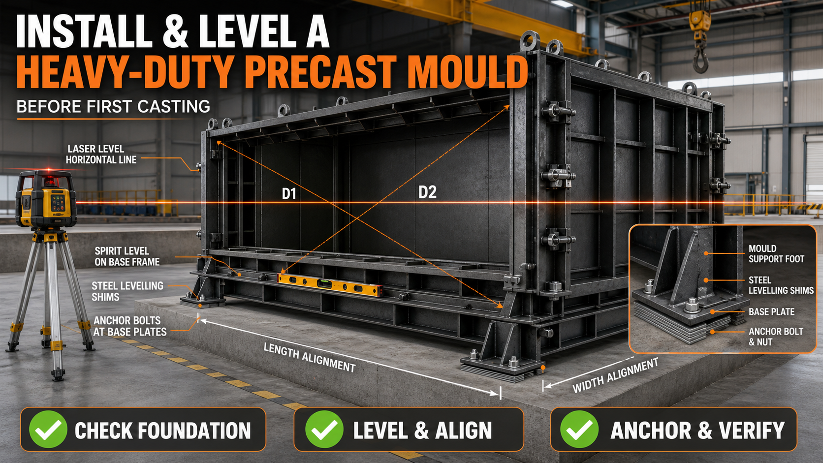
How to Install and Level a Heavy-Duty Precast Mould Before First Casting
How to Install and Level a Heavy-Duty Precast Mould Before First Casting
A heavy-duty iron precast mould must be installed on a stable, level and properly prepared foundation before production begins.
Even a precisely manufactured mould can produce inaccurate components if it is installed on an uneven floor or supported at incorrect points.
Poor installation may cause frame twisting, shutter misalignment, concrete slurry leakage, unequal product thickness and difficulty during demoulding.
The mould should therefore be positioned, levelled, aligned and inspected before the first concrete casting.
Why Correct Mould Installation Is Important
Correct installation helps the mould to:
• Maintain accurate internal dimensions • Remain level during concrete pouring • Keep shutters properly aligned • Prevent frame twisting • Maintain uniform product thickness • Reduce concrete slurry leakage • Support controlled vibration • Operate locks and hinges smoothly • Improve demoulding • Reduce premature mould wear • Produce consistent precast products • Improve production safety
A mould should not be placed directly into production immediately after unloading.
Information Required Before Installation
Before installing the mould, confirm:
• Mould dimensions • Mould weight • Product dimensions • Filled mould weight • Lifting-point locations • Supporting-point locations • Foundation requirements • Anchor-bolt arrangement • Required operating space • Shutter-opening direction • Concrete feeding method • Vibration system • Product lifting direction • Crane coverage • Electrical or hydraulic requirements
Obtain the latest mould drawing and installation instructions before starting work.
Prepare the Installation Area
The installation area should be clean, stable and large enough for the complete production process.
Check that sufficient space is available for:
• Mould positioning • Shutter opening • Reinforcement-cage placement • Concrete pouring • Vibrator installation • Operator access • Product demoulding • Crane movement • Cleaning and maintenance • Concrete shifting trolley movement
Do not position the mould where columns, walls, stored materials or nearby machinery restrict shutter movement.
Foundation Requirements
The foundation must support the combined loads from:
• Empty iron mould • Reinforcement cage • Fresh concrete • Workers and tools • Concrete bucket or trolley • Vibration forces • Demoulding operations • Product lifting • Dynamic production loads
Foundation thickness, reinforcement, bearing capacity and anchor details should be determined by qualified technical personnel according to the actual loads and site conditions.
The installation surface should be:
• Structurally adequate • Firm and stable • Properly drained • Free from loose material • Within the approved level requirement • Capable of supporting all mould feet • Accessible for inspection and cleaning
Do not install a large mould on weak flooring or loose soil without an engineered supporting arrangement.
Inspect the Mould Before Unloading
Before positioning the mould, inspect it for transportation damage.
Check:
• Main base frame • Iron casting plates • Structural stiffeners • Lifting points • Hinges • Locks and clamps • Hydraulic components • Vibrator brackets • Welded joints • Removable shutters • Inserts and accessories
Record any damage before installation. A bent frame should not be forced into alignment through anchor bolts.
Plan the Lifting Operation
A heavy-duty iron mould may have an uneven centre of gravity, especially when shutters, hydraulic cylinders or accessories are fitted on one side.
Before lifting:
• Confirm the total mould weight • Identify approved lifting points • Check crane capacity • Select suitable slings and shackles • Inspect all rigging equipment • Determine the centre of gravity • Plan the travel route • Establish an exclusion zone • Assign trained personnel • Prepare the landing area
Only designated lifting points should be used. Do not attach slings to shutters, stiffeners, handles or locking mechanisms unless those points are specifically designed for lifting.
Keep all personnel clear of the suspended mould.
Position the Mould Correctly
Lower the mould gradually onto its specified supporting points.
Before final placement, verify:
• Casting direction • Product-removal direction • Shutter-opening clearance • Crane-hook approach • Concrete-delivery route • Operator access • Vibrator access • Cleaning access • Drainage direction • Connection with other production equipment
Avoid repeatedly dragging the iron mould across the factory floor because this can damage its feet and twist the frame.
Initial Levelling
Begin levelling from the main structural base frame instead of using a removable shutter or thin casting edge as the reference.
Suitable tools may include:
• Precision spirit level • Laser level • Surveying instrument • Straightedge • Steel measuring tape • Feeler gauge • Engineer’s level
Take readings at:
• All four corners • Main supporting feet • Centre of long sides • Centre of short sides • Intermediate frame points • Critical casting surfaces
A single reading cannot confirm that a large mould is level.
Levelling a Long Mould
Long wall-panel, pole and beam moulds should be checked at multiple stations along their complete length.
A mould may be level at both ends but sag or rise in the centre.
Use a laser level or suitable surveying equipment to compare:
• End elevations • Centre elevation • Intermediate supports • Left and right frame rails • Casting-surface reference points
Record every reading before making adjustments.
Levelling Supports and Shims
Use engineered levelling plates, suitable steel shims, adjustable feet or another approved support system.
Shims should:
• Be strong enough for the load • Provide full and stable contact • Remain securely positioned • Resist vibration • Avoid point loading • Be protected from accidental movement
Do not use loose bricks, wood pieces, stones or unstable scrap material as permanent mould supports.
After levelling, confirm that every designed support point carries load. An unsupported foot may allow the frame to move during casting.
Check Mould Alignment
Alignment confirms whether the mould follows the required straight line.
To check alignment:
1. Establish a fixed reference line. 2. Use a string line, laser or surveying instrument. 3. Check both sides of the mould. 4. Measure offsets at several locations. 5. Adjust the mould position gradually. 6. Recheck after every adjustment.
For multiple moulds installed in one production line, verify both individual mould alignment and overall line alignment.
Check Squareness
For a rectangular mould, measure both internal diagonals.
Procedure:
1. Measure from the first internal corner to the opposite corner. 2. Record the first diagonal. 3. Measure the second diagonal. 4. Compare both measurements. 5. Adjust the frame or shutters if required. 6. Recheck length, width and diagonals.
Equal diagonals generally indicate squareness, but final acceptance should follow the mould drawing and approved tolerance.
Check Internal Dimensions
Measure the mould after it has been assembled and locked in its normal casting position.
Check:
• Internal length • Internal width • Product thickness • Diagonal dimensions • Corner angles • Opening dimensions • Rebate dimensions • Insert positions • Sidewall verticality • Opposite-side parallelism
Take measurements at multiple locations because the mould may be correct at one end and out of tolerance at another.
Check Shutter Operation
Open and close every shutter before anchoring the mould permanently.
Confirm that:
• Hinges move smoothly • Locks engage completely • Clamps apply uniform pressure • Shutters do not contact the floor • Joints close without visible gaps • Hydraulic cylinders move correctly • Removable sections fit properly • Safety supports operate correctly
Levelling adjustments can change shutter alignment, so the operation must be checked again after every major adjustment.
Anchoring the Mould
Some moulds remain fixed to the foundation, while others are designed to stay movable.
If anchoring is required, the anchor-bolt size, embedment, spacing and installation method should follow the approved mould and foundation design.
Before tightening anchor bolts:
• Confirm final position • Confirm level • Confirm alignment • Confirm squareness • Confirm shutter operation • Confirm all support points • Verify anchor-hole positions
Tighten anchors in a controlled and balanced sequence.
Excessive or uneven tightening can pull the frame out of level. Measure the mould again after tightening.
Grouting Under the Base Frame
Where specified, non-shrink grout may be placed beneath base plates to provide uniform support.
Before grouting:
• Clean the foundation • Remove loose material • Confirm mould level • Seal the grout area • Follow the grout manufacturer’s instructions • Prevent movement during curing
Do not begin casting until the grout has achieved the required strength and the installation has been approved.
Vibrator Installation
Shutter vibrators or external vibrators should be installed only at designed mounting locations.
Check:
• Vibrator type and capacity • Mounting bracket strength • Bolt tightness • Cable or hose routing • Electrical protection • Rotation or operating direction • Clearance from locks and hinges • Access for maintenance
Do not weld a vibrator bracket at an arbitrary location after final alignment because welding heat may distort the mould plate.
Hydraulic and Mechanical Connections
For hydraulic moulds, inspect:
• Hydraulic cylinders • Hoses and fittings • Oil level • Operating pressure • Control valves • Pin connections • Mechanical stops • Leakage • Emergency controls
Cycle the shutters without concrete and confirm smooth, controlled movement.
Electrical connections should be completed by qualified personnel and protected from water, concrete slurry and vehicle traffic.
Trial Assembly
Before the first casting, perform a complete dry trial.
The trial should include:
• Opening the mould • Closing every shutter • Engaging all locks • Operating hydraulic components • Checking joint closure • Measuring internal dimensions • Checking diagonals • Checking level • Installing a sample insert arrangement • Confirming reinforcement-cage clearance • Simulating product-lifting access
Correct every problem before concrete is poured.
Leakage Inspection
Inspect all mould joints for possible slurry-leakage points.
Pay attention to:
• Bottom joints • Vertical shutter joints • Corners • Insert openings • Bolt holes • Gasket locations • Welded seams • Removable sections
Clean the contact surfaces and replace damaged sealing material where necessary.
A controlled water test may be used when approved. Dry and protect the iron mould afterward to prevent corrosion.
Release-Agent Application
Before first casting:
1. Clean the iron casting surface. 2. Remove dust, rust, oil and fabrication residue. 3. Use a release agent compatible with the concrete finish. 4. Apply a thin and uniform coating. 5. Avoid pooling in corners. 6. Prevent contamination of reinforcement. 7. Keep sealing surfaces clean where required.
Excessive release agent can create stains and surface defects.
First Casting Procedure
The first production cycle should be treated as a controlled trial.
During the first casting:
• Confirm pre-pour approval • Pour concrete gradually • Observe all mould supports • Monitor shutter joints • Check for slurry leakage • Operate vibrators according to procedure • Watch locks and clamps • Stop if abnormal movement occurs • Record production observations
Do not continue filling if the mould shifts, twists or develops a major joint opening.
Post-Casting Level Check
A mould may remain level when empty but move after receiving concrete and vibration loads.
During or after the first controlled casting, check for:
• Settlement at supporting feet • Frame movement • Opened joints • Unequal concrete depth • Loose anchor bolts • Shutter displacement • Excessive vibration • Concrete leakage
Any movement should be investigated before the next casting cycle.
First Demoulding Inspection
After the product has achieved approved demoulding strength:
• Release locks gradually • Open shutters in sequence • Check for binding • Lift from approved points • Inspect product dimensions • Check edges and surface finish • Record leakage marks • Inspect the iron mould for movement • Recheck level and diagonals
The first finished product provides useful evidence about mould alignment and installation accuracy.
Common Installation Mistakes
Installing on an Uneven Floor
This can twist the base frame and create dimensional errors.
Using Unstable Packing
Wood, bricks and loose scrap may compress or move under vibration.
Levelling From a Removable Shutter
The main base frame should normally provide the stable installation reference.
Anchoring Before Final Alignment
Anchor bolts can make later adjustment difficult and may pull the mould out of shape.
Checking Only Four Corners
Long moulds may require intermediate supports and readings.
Ignoring Filled-Mould Weight
The foundation must support the mould, reinforcement, fresh concrete and production loads.
Dragging the Mould
Dragging can damage supporting feet and distort the frame.
Using Stiffeners as Lifting Points
Structural stiffeners are not automatically approved lifting points.
Casting Without a Dry Trial
Operational problems should be identified before concrete enters the mould.
Failing to Recheck After Tightening
Anchor bolts and clamps can change mould alignment.
Pre-Casting Installation Checklist
Foundation:
• Load capacity approved • Surface clean and stable • Drainage available • Installation level checked • Anchor locations confirmed
Mould Position:
• Correct production direction • Adequate shutter clearance • Crane coverage confirmed • Concrete route clear • Maintenance access available
Geometry:
• Base frame level • Length verified • Width verified • Diagonals checked • Sidewalls vertical • Opposite sides parallel • Product thickness correct
Operation:
• Hinges move freely • Locks close correctly • Hydraulic system tested • Vibrators securely installed • Joints properly sealed • Inserts correctly positioned
First Casting:
• Release agent applied • Reinforcement clearance checked • Pre-pour inspection recorded • Emergency stop procedure available • Mould movement monitored • Product dimensions checked after demoulding
Final Conclusion
Correct installation and levelling are essential for achieving reliable performance from a heavy-duty iron precast mould.
The foundation must support the complete operating load. The main frame should be level at every designed support point, while internal dimensions, diagonals, straightness and shutter alignment should match the approved mould drawing.
Anchoring, grouting, vibration and hydraulic connections should be completed only after final alignment has been confirmed.
A dry trial and controlled first casting help identify movement, slurry leakage and dimensional problems before regular production begins.
Paras Steel Industries manufactures customised heavy-duty iron precast moulds with structural stiffeners, reliable locking systems, lifting points and manual or hydraulic operating arrangements.
For installation planning and customised mould specifications, share your product drawing, mould dimensions, daily production target, factory layout and available lifting system with Paras Steel Industries.
Safety Note:
Mould lifting, foundation design, anchoring, electrical connections and hydraulic installation must be completed by competent or qualified personnel according to the mould drawing, equipment instructions and applicable local safety requirements.