
Precast Mould Maintenance Guide
Garden Bench Mould Parting-Line Leakage: Joint Sealing, Concrete Fins and Finish Control
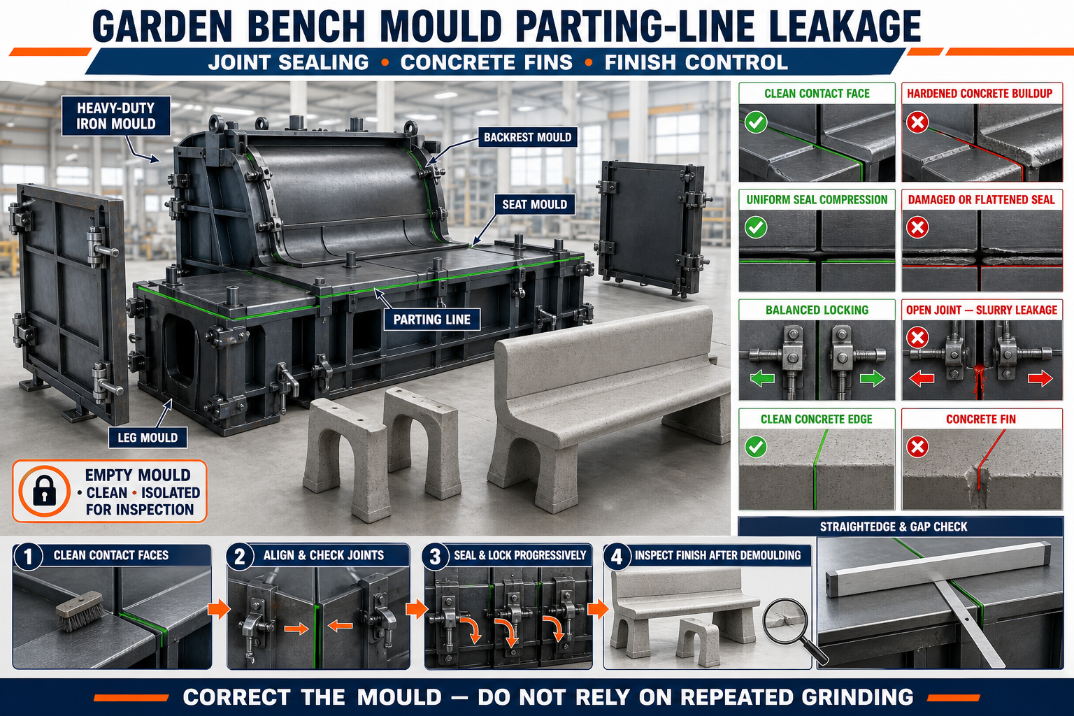
Parting lines occur where the shutters and removable sections of a garden bench mould meet. Dirty contact faces, uneven locking or damaged joints can allow cement slurry to escape and create concrete fins. This guide explains joint inspection, sealing, leakage prevention and finish control for heavy-duty iron garden bench moulds.
By Paras Steel Industries ·
Garden Bench Mould Parting-Line Leakage: Joint Sealing, Concrete Fins and Finish Control
Garden Bench Mould Parting-Line Leakage: Joint Sealing, Concrete Fins and Finish Control
Precast garden benches are assembled from components such as the seat, backrest, legs and supporting frames. Each concrete component requires a correctly designed and accurately assembled mould.
A heavy-duty iron garden bench mould may contain several removable shutters and profile-forming sections. The lines where these components meet are known as parting lines.
If the mating surfaces do not close correctly, fresh cement slurry can escape through the joint. The leaked slurry may create concrete fins, rough edges, honeycombing and inconsistent surface finish.
Regular inspection and correct joint sealing help produce cleaner concrete components and reduce grinding or repair work.
What Is a Mould Parting Line?
A parting line is the joint between two mould components that separate during demoulding.
Parting lines may occur between:
• Base plate and side shutter • Side shutter and end shutter • Seat-profile sections • Backrest-forming plates • Bench-leg mould shutters • Removable inserts • Decorative-profile liners • Corner-forming components • Hinged and fixed mould sections
A visible line on the finished concrete is not always a defect. However, excessive fins, steps or surface damage indicate a mould or process problem.
Why Garden Bench Moulds Use Parting Lines
A concrete garden bench component may contain slopes, curves, recesses or decorative details. It cannot always be removed from a single rigid cavity.
Parting lines allow the mould to:
• Open around the concrete component • Release curved profiles • Remove side and end shutters • Protect concrete edges • Simplify cleaning • Support replaceable design sections • Accommodate multiple bench components • Provide access to reinforcement
Their position should support both production accuracy and easy demoulding.
What Is Parting-Line Leakage?
Parting-line leakage occurs when cement paste or slurry passes through a gap between mould components during concrete placement or vibration.
The leakage may appear as:
• Wet cement paste outside the joint • Thin concrete fins • Hardened slurry below the mould • Rough parting lines • Honeycombing near the joint • Loss of sharp profile definition • Discoloured concrete areas • Difficult shutter opening
Leakage should be traced to its exact joint location.
Why Cement Slurry Escapes
Cement slurry can pass through very small openings.
Common causes include:
• Hardened concrete on contact faces • Loose locks or clamps • Damaged sealing strips • Bent iron shutters • Worn hinges • Misaligned locating pins • Cracked welds • Uneven mould assembly • Excessive vibration • Incorrect concrete consistency • Damaged profile inserts • Foreign material in the joint • Poor mould-bed support
Applying additional sealant without correcting the gap may provide only temporary improvement.
What Are Concrete Fins?
Concrete fins are thin, raised projections formed where slurry enters a mould gap and hardens.
Fins commonly occur along:
• Seat edges • Backrest sides • Bench-leg corners • End faces • Decorative-profile joints • Shutter intersections
Thin fins may break during handling and leave rough edges. Larger fins may require grinding and can indicate a significant mould-alignment problem.
How Leakage Affects Bench Finish
Parting-line leakage can cause:
• Rough concrete edges • Visible joint marks • Inconsistent profiles • Surface staining • Honeycombing • Chipped corners • Extra finishing work • Poor assembly fit • Increased rejection • Reduced production efficiency
A decorative garden bench requires particular attention to visible surfaces.
Garden Bench Mould Components
A garden bench mould set may include separate iron moulds for:
• Seat slab • Backrest • Supporting legs • Side frames • Armrest components where specified • Decorative inserts • Connecting blocks • Project-specific accessories
Each component may contain different parting-line locations and sealing requirements.
Heavy-Duty Iron Mould Construction
Reliable mould construction may include:
• Smooth steel forming plates • Structural stiffeners • Accurate corner joints • Hinged shutters • Removable end plates • Quick locks • Locating pins • Profile inserts • Base frame • Adjustable or fixed supports • Mould lifting points
The mould should be sufficiently rigid to maintain joint contact during concrete placement and vibration.
Identifying Critical Parting Lines
Before production, mark the joints most likely to leak.
Critical locations often include:
• Long horizontal seat joints • Curved backrest transitions • Leg-mould corners • End-shutter intersections • Decorative liner joints • Hinged-shutter edges • Locations near vibrator mounting points • Joints below concrete filling level
A joint-inspection map can help record repeated leakage.
Preparing the Mould for Joint Inspection
Before checking the mould:
• Remove the finished component • Clean all forming surfaces • Open removable shutters • Isolate powered equipment • Mechanically support moving sections • Remove hardened slurry • Clean locating pins and locks • Inspect the supporting frame • Review the component drawing • Keep suitable inspection tools ready
Do not inspect pinch-point areas while the shutters can move.
Cleaning Contact Faces
Clean mating surfaces are essential for tight joint closure.
Remove:
• Hardened cement paste • Concrete particles • Rust flakes • Old sealing material • Grease deposits • Release-agent buildup • Grinding dust • Foreign objects
Avoid aggressive cleaning that dents or scratches the forming surface.
Checking Parting-Line Contact
After cleaning, close the mould lightly and inspect the complete joint.
Check for:
• Visible gaps • Uneven contact • Local high points • Misaligned edges • Light passing through the joint • Loose shutters • Changed lock position • Steps between forming surfaces • Contact only near clamps
A joint may close correctly at the locks while remaining open between them.
Using a Straightedge and Feeler Gauge
A verified straightedge can help identify distortion along a shutter.
A suitable gauge may help locate gaps between contact faces.
Check:
• Along the complete joint • At both ends • Between locking points • Around curves • At profile transitions • Near hinges • Around removable inserts
Acceptance requirements should follow the mould and product drawings.
Checking Shutter Alignment
Shutters should be checked against fixed mould datums.
Possible references include:
• Base-plate edge • Mould centreline • Fixed locating stop • Machined contact face • Verified corner • Base-frame datum
Do not align one movable shutter only against another unchecked shutter.
Checking Mould Squareness
Out-of-square mould assembly can open joints and change component dimensions.
Squareness may be checked by:
• Comparing diagonals • Measuring cavity width at several points • Using an approved engineer’s square • Checking end-shutter orientation • Comparing opposite side positions
Recheck squareness after the locks are fully engaged.
Inspecting Hinges and Pins
Worn hinges may allow shutters to sag.
Inspect for:
• Pin wear • Bush wear • Excessive movement • Misaligned hinge leaves • Loose mounting bolts • Cracked welds • Rust or binding • Uneven shutter height
Replacing a seal will not correct a sagging hinge.
Inspecting Locks and Clamps
Locks should apply balanced pressure across the joint.
Check:
• Wedge surfaces • Screw threads • Clamp pivots • Mounting brackets • Lock alignment • Wear marks • Loose fasteners • Cracked welds • Consistent engagement • Accessibility for cleaning
Do not use improvised pipe extensions to create excessive clamping force.
Balanced Locking Sequence
A general locking procedure may include:
1. Clean the Mould Joint
Remove concrete and foreign material.
2. Close the Shutter Carefully
Allow locating pins and guides to seat.
3. Engage Primary Locators
Confirm the shutter position before applying force.
4. Apply Locks Lightly
Engage every lock without fully tightening one point.
5. Check Joint Alignment
Inspect the parting line along its complete length.
6. Tighten Progressively
Apply balanced pressure in a planned sequence.
7. Recheck Contact
Confirm tightening has not distorted the shutter.
8. Complete Pre-Pour Inspection
Verify all joints and locks before casting.
Excessive force at one lock can create a gap elsewhere.
Joint-Sealing Options
Sealing methods depend on the mould design and required concrete finish.
Approved options may include:
• Precision metal-to-metal contact • Replaceable sealing strip • Suitable mould gasket • Approved compressible seal • Project-specific joint-sealing component
Sealing materials should be compatible with the mould, concrete and release agent.
Improvised materials should not be used as permanent seals.
Requirements of a Good Seal
A suitable joint seal should:
• Fit the designed groove • Remain continuous • Resist displacement • Compress evenly • Avoid changing component dimensions • Remain compatible with release agent • Withstand production conditions • Allow proper demoulding • Be easy to inspect and replace
A seal that is too thick can prevent full mould closure.
Installing a Sealing Strip
A general installation procedure may include:
• Clean the seal groove • Remove old adhesive or residue • Inspect the groove for damage • Select the approved seal • Install without stretching • Keep corners continuous • Avoid overlaps unless specified • Check even seating • Close the shutter gently • Verify joint contact
Replace seals that are cut, flattened, hardened or permanently deformed.
Applying Mould Release Agent
Release agent should be applied after cleaning and joint preparation.
Apply it:
• In a thin, uniform coat • Across forming surfaces • Around profile details • Near parting lines without excessive pooling • According to the supplier’s instructions
Excessive release agent can collect at the joint and affect the concrete finish.
Concrete Mix and Leakage
A highly fluid mix may pass more easily through mould gaps. However, the solution is not simply to make the concrete excessively dry.
Concrete should follow the approved mix design for:
• Required strength • Workability • Compaction method • Surface finish • Reinforcement arrangement • Production cycle
Mould joints should be mechanically sound regardless of normal approved concrete variations.
Concrete Placement Near Parting Lines
During casting:
• Place concrete evenly • Avoid direct impact on shutters • Prevent reinforcement movement • Monitor long joints • Keep locks visible where possible • Check for early leakage • Avoid overfilling one area • Follow the approved placement sequence
A leak discovered early may indicate that casting should be stopped safely for inspection.
Vibration and Joint Leakage
Vibration can increase leakage when joints are loose or misaligned.
Before vibration:
• Check every lock • Confirm shutter alignment • Inspect seals • Verify mould support • Remove loose tools • Confirm vibrator mounting
During vibration, observe for:
• Fresh slurry at joints • Lock movement • Shutter movement • Unusual noise • Local plate vibration • Growing gaps
Avoid excessive vibration duration or intensity.
Immediate Response to Leakage
If significant leakage is observed:
• Stop the process safely where possible • Isolate vibration • Identify the leak location • Keep hands away from moving components • Follow the plant’s corrective procedure • Record the joint position • Inspect after safe access is available
Do not attempt to tighten unsafe or inaccessible locks during operation.
Preparing for Demoulding
Before opening the garden bench mould:
• Confirm adequate concrete strength • Support the component • Clean concrete around locks • Identify the opening sequence • Isolate powered equipment • Mechanically secure shutters • Keep personnel clear of pinch points • Prepare approved handling equipment
The correct demoulding time depends on the concrete mix, curing process and component design.
Correct Demoulding Procedure
A general process may include:
1. Release Secondary Locks
Open locks progressively without sudden movement.
2. Support Removable Shutters
Prevent heavy iron components from dropping.
3. Release Primary Locks
Open the remaining connections in the approved order.
4. Separate Along the Parting Line
Use the designed opening direction.
5. Protect Concrete Edges
Avoid dragging shutters across fresh corners.
6. Remove the Component Safely
Use the approved handling method.
7. Inspect the Parting Line
Check for fins, chips and surface damage.
8. Clean the Mould Immediately
Remove fresh slurry before it hardens.
Do not pry directly against a visible finished surface.
Removing Concrete Fins
Finished components should be inspected before corrective finishing.
Minor fins may be removed using the approved finishing procedure after the concrete has sufficient strength.
Before grinding or repair:
• Confirm the defect is superficial • Protect adjoining finished surfaces • Use appropriate PPE • Avoid changing component dimensions • Inspect for hidden cracks • Record recurring fin locations • Correct the mould before the next pour
Fin removal should not become a substitute for mould maintenance.
Finish-Control Inspection
After demoulding, inspect:
• Seat edges • Backrest edges • Bench-leg corners • Parting-line continuity • Decorative profiles • Surface texture • Concrete fins • Honeycombing • Chips • Cracks • Colour variation • Assembly contact surfaces
Visible surfaces may require stricter finish control than concealed connections.
Tracking Defects by Mould Position
Record each defect according to:
• Mould identification • Component type • Cavity number • Joint location • Casting date • Operator observation • Seal condition • Lock condition • Vibration method • Repair action
A repeated fin at the same position usually points to a local mould problem.
Troubleshooting Common Problems
Problem: Thin Fin Along the Complete Joint
Possible causes:
• Continuous joint gap • Seal is too thin or worn • Shutter is misaligned • Contact face is dirty • Locks apply insufficient pressure
Problem: Thick Fin Between Two Locks
Possible causes:
• Shutter is bowed • Lock spacing is inadequate • Stiffener is damaged • Concrete pressure opens the unsupported section
Problem: Leakage at One Corner
Possible causes:
• Damaged seal transition • Concrete buildup • Bent shutter corner • Misaligned end plate • Weak corner lock
Problem: Honeycombing Near the Parting Line
Possible causes:
• Slurry escaped • Concrete placement was uneven • Compaction was insufficient • Reinforcement is congested • Aggregate bridging occurred
Problem: Shutter Is Difficult to Open
Possible causes:
• Concrete fin has locked the joint • Release agent is missing • Lock remains engaged • Hinge is binding • Shutter is distorted • Seal has adhered to the component
Problem: Visible Step Across the Concrete Joint
Possible causes:
• Forming surfaces are at different levels • Locating pin is worn • Shutter is sagging • Lock has pulled the plate out of alignment • Previous repair changed the surface position
Mould Repair Considerations
Before repairing an iron shutter:
• Measure the existing distortion • Identify the root cause • Check supporting stiffeners • Inspect welds • Protect forming surfaces • Control welding heat • Recheck straightness • Trial-assemble the mould • Verify joint contact • Record the repair
Uncontrolled welding can create additional distortion and leakage paths.
Parting-Line Maintenance Checklist
After every casting cycle:
• Clean all contact faces • Remove slurry from joints • Inspect seals • Check hinges and bushes • Inspect locating pins • Check locks and clamps • Examine structural stiffeners • Inspect welds • Check shutter straightness • Lubricate approved moving points • Apply corrosion protection during storage • Record recurring leakage locations
Seals and locks should be treated as production-quality components.
Pre-Pour Joint Inspection Checklist
Before placing concrete, confirm:
• Mould components are clean • Correct shutters and inserts are installed • Contact faces are flat • Seals are continuous • Locating pins are seated • Hinges are stable • Locks are progressively tightened • Parting lines are closed • Cavity dimensions are verified • Reinforcement has adequate clearance • Release agent is uniformly applied • Mould support is stable • No tools remain inside the mould
Benefits of Controlling Parting-Line Leakage
Effective leakage control provides:
• Cleaner bench components • Smaller and more consistent joint marks • Reduced concrete fins • Lower grinding and repair work • Better decorative finish • Improved assembly fit • Reduced concrete waste • Faster production • Longer mould service life • Fewer rejected components
Conclusion
Parting-line leakage in a garden bench mould usually begins with dirty contact faces, worn seals, uneven locking, damaged hinges or distorted iron shutters.
A reliable maintenance process should include complete joint cleaning, fixed-datum alignment, balanced locking and inspection during vibration. Concrete fins and finish defects should be recorded by mould location so recurring mechanical problems can be corrected.
A properly maintained heavy-duty iron garden bench mould helps manufacturers produce clean seat, backrest and leg components with consistent edges, attractive surfaces and reduced finishing work.