
Precast Infrastructure Moulds
Friction Slab Barrier Mould: Applications, Specifications and Buying Guide
Learn how to select a friction slab barrier mould by comparing barrier dimensions, iron plate thickness, opening system and project applications.
By Paras Steel Industries ·
Friction Slab Barrier Mould: Applications, Specifications and Buying Guide
Friction Slab Barrier Mould: Applications, Specifications and Buying Guide
Road and bridge infrastructure requires dependable safety barriers capable of controlling vehicle movement and protecting the edges of elevated or high-speed corridors.
A friction slab barrier combines a vertical concrete safety barrier with a wide horizontal base slab. The integrated L-shaped profile uses the weight and friction of the base to improve stability.
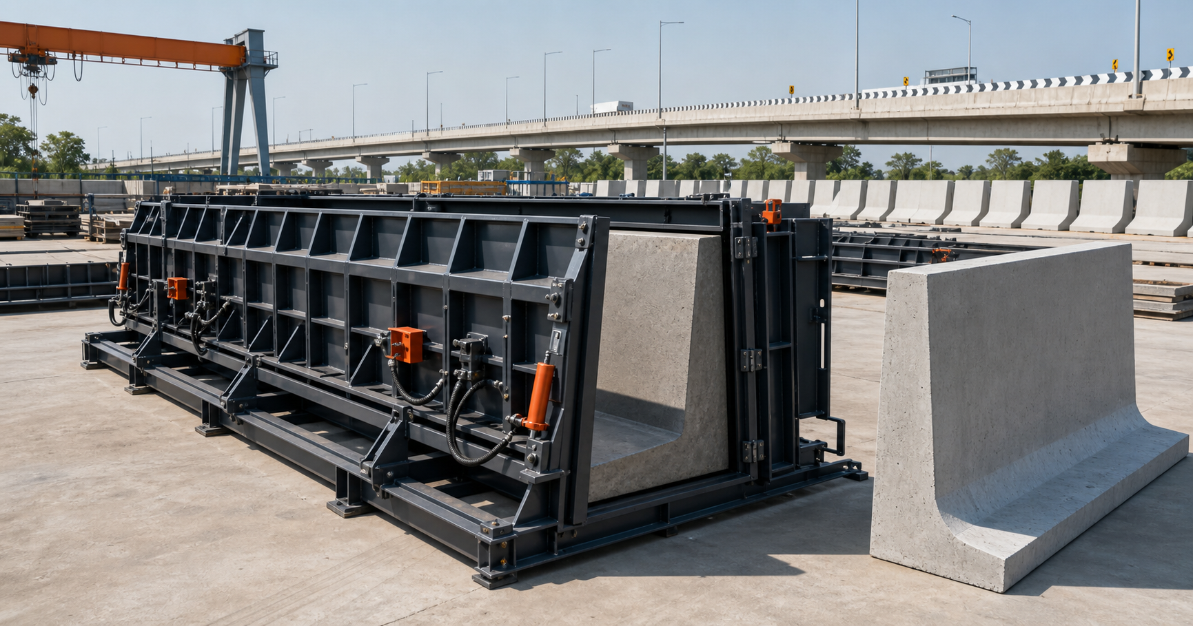
A friction slab barrier mould enables precast manufacturers to cast the vertical wall and horizontal slab as one monolithic concrete unit.
Because these components are large and heavy, the mould requires strong iron construction, a reinforced support frame, leak-resistant joints and a convenient opening system.
This guide explains the applications, dimensions, specifications, operational features and buying factors of a precast friction slab barrier mould.
What Is a Friction Slab Barrier?
A friction slab barrier is a precast concrete road-safety component with an integrated L-shaped profile.
Its vertical section functions as a crash barrier or protective wall. The horizontal base rests on the prepared ground or structure and increases stability through its weight and contact area.
Unlike a basic upright barrier, a friction slab unit includes a substantially wider foundation slab. This configuration is used where a project requires an integrated barrier and base arrangement.
The final barrier dimensions, reinforcement and concrete grade must follow the approved project design.
What Is a Friction Slab Barrier Mould?
A friction slab barrier mould is a heavy-duty iron form used to manufacture monolithic L-shaped concrete barrier units.
The mould creates the vertical barrier profile, horizontal base slab and required edges in one casting operation.
It generally includes:
Heavy-duty iron skin plates
Vertical and horizontal shutters
Reinforced channel framework
Structural iron angles
Hinged opening system
Mechanical or hydraulic controls
Heavy clamps and locking hardware
Rubber-gasket sealing joints
External vibrator mounting brackets
Custom insert provisions
The shutters are closed and locked before reinforcement and concrete are placed inside the mould. After vibration and curing, the hinged side panels are opened for demoulding.
Benefits of Monolithic L-Shaped Casting
Integrated Construction
The vertical barrier and horizontal slab are cast as one concrete component. This eliminates a separate connection between the two sections.
Improved Dimensional Consistency
A precision-fabricated mould helps maintain the required barrier height, base width and slab thickness during every casting cycle.
Better Surface Finish
Smooth contact surfaces and slurry-tight joints help produce cleaner concrete faces and defined profile edges.
Controlled Factory Production
Reinforcement placement, concrete pouring, vibration and curing can be managed under controlled production conditions.
Faster Site Installation
Ready precast units can be transported and installed according to the project schedule, reducing the need for extensive on-site shuttering.
Repeat Manufacturing
A heavy-duty iron mould can support repeated casting when it is operated, cleaned and maintained correctly.
Primary Applications
Flyover Approach Roads
Friction slab barriers can be used along flyover ramps and elevated approach roads where traffic requires a defined protective boundary.
Highways and Expressways
The barriers may be installed along highway shoulders, expressway edges and other high-speed road corridors according to the approved road-safety design.
Bridge Approaches
L-shaped barriers can support safety arrangements on bridge approach roads and transition areas.
Elevated Corridors
Urban elevated roads and grade-separated corridors require dependable edge-protection systems.
RE Wall Borders
The barriers can be used around reinforced earth wall approaches and boundary sections where the project design specifies an integrated slab.
Central Medians
Custom profiles may be used for selected central-median and traffic-separation applications.
Hill Roads
Mountain highways and sloped infrastructure may require heavy concrete barriers for vehicle and edge protection.
Rail and Transit Infrastructure
Project-specific friction slab units may be used around elevated transit corridors, service roads and restricted infrastructure zones.
Standard Highway Barrier Dimensions
Common friction slab barrier dimensions may include:
Barrier height: approximately 900 to 1100 mm
Base width: approximately 1200 to 2000 mm
Slab thickness: approximately 200 to 350 mm
Segment length: approximately 2, 3 or 4 metres
These dimensions are indicative. The final mould should follow the approved project drawing.
Heavy Bridge and Flyover Barrier Dimensions
Heavier barrier configurations may include:
Barrier height: approximately 1150 to 1400 mm
Base width: approximately 2000 to 2500 mm
Slab thickness: approximately 300 to 400 mm
Segment length: approximately 3 to 6 metres
The required dimensions depend on project design, installation location, loading conditions and transport limitations.
Custom Dimensions
Friction slab barrier moulds can be manufactured according to project-specific dimensions.
Buyers should provide information including:
Vertical barrier height
Barrier-top width
Barrier-base width
Horizontal slab width
Slab thickness
Total segment length
End profile
Chamfer requirements
Reinforcement arrangement
Lifting-point provisions
Drainage or utility openings
Connection and alignment details
Technical Specifications
Mould Profile
The mould is designed for integrated L-shaped casting consisting of a vertical crash-barrier wall and horizontal friction slab.
Iron Plate Thickness
The concrete-contact surfaces can use approximately:
6 mm heavy-duty iron plate
8 mm heavy-duty iron plate
10 mm heavy-duty iron plate
The selected thickness depends on the mould dimensions, concrete pressure, expected production frequency and support-frame arrangement.
Framework and Stiffeners
Heavy channels of approximately 100 mm or 125 mm may be used as part of the mould’s structural framework.
Heavy iron angles and stiffeners reinforce the shutters and help prevent bulging during concrete pouring and vibration.
The exact section size and spacing should be determined according to the final mould dimensions and load.
Opening Mechanism
The side formwork can use a mechanical or hydraulic hinged-opening system.
The appropriate mechanism depends on:
Shutter size and weight
Required daily production
Available labour
Factory power setup
Production budget
Desired demoulding time
Joint Sealing
Machined or accurately matched flange joints can include heavy rubber-gasket strips.
The sealing system helps reduce cement slurry leakage and supports cleaner concrete surfaces and edges.
Vibrator Mounting
External vibrator mounting plates can be provided on the outer shutters.
External vibration helps compact concrete around dense reinforcement and inside the barrier profile.
Surface Protection
The iron mould should receive suitable anti-rust surface protection and durable industrial paint on its non-contact surfaces.
Concrete-contact surfaces should be cleaned and protected using an appropriate mould-release system.
Production Durability
A properly designed and maintained heavy-duty iron mould can support repeated production cycles.
Actual service life depends on:
Mould handling
Cleaning practices
Concrete buildup
Release-agent application
Shutter alignment
Vibration intensity
Storage conditions
Rust protection
Preventive maintenance
Importance of an Anti-Bulge Framework
Fresh concrete creates substantial pressure against the vertical and horizontal shutters.
A weakly supported shutter can bend or bulge, resulting in incorrect barrier dimensions and an uneven concrete surface.
The outer grid framework uses heavy channels, angles and stiffeners to distribute the concrete load.
A properly designed framework helps:
Maintain the barrier profile
Control plate deflection
Support the shutter weight
Hold flange joints together
Manage vibration forces
Maintain repeatable dimensions
Buyers should evaluate the complete support system rather than considering only the iron plate thickness.
Mechanical vs Hydraulic Opening
Mechanical Opening System
A mechanical mould may use ratchets, jacks, clamps and hinged shutters.
Potential benefits include:
Simple operating arrangement
No hydraulic power-pack requirement
Suitable for controlled production
Lower system complexity
However, large shutters may require greater labour and more time to operate manually.
Hydraulic Opening System
A hydraulic system uses cylinders or controlled levers to move the mould shutters.
Potential benefits include:
Faster shutter opening
Reduced manual effort
Controlled movement
Convenient high-volume production
Quicker production turnaround
The hydraulic arrangement should be designed according to the shutter size, weight and opening direction.
Concrete Casting Process
Step 1: Inspect and Clean the Mould
Remove concrete residue and inspect the shutters, hinges, locks and gasket joints.
Step 2: Apply Release Agent
Apply a suitable mould-release agent evenly to concrete-contact surfaces.
Step 3: Position the Reinforcement
Place the approved reinforcement cage inside the mould using appropriate spacers and supports.
Step 4: Install Inserts
Position lifting anchors, alignment provisions and other approved inserts according to the project drawing.
Step 5: Close the Shutters
Close the hinged panels and tighten the locks evenly. Check that gasket joints are correctly seated.
Step 6: Verify Dimensions
Confirm the internal profile, barrier height, base width, slab thickness and segment length before pouring.
Step 7: Pour the Concrete
Place concrete in a planned sequence to avoid excessive pressure at one location.
Step 8: Compact the Concrete
Use appropriate external or internal vibration to remove trapped air and fill areas around the reinforcement.
Step 9: Finish and Cure
Level exposed surfaces and cure the component according to the approved concrete procedure.
Step 10: Demould Carefully
Open the shutters after the concrete achieves adequate strength. Avoid sudden movement that could damage edges.
Step 11: Inspect the Barrier
Check dimensions, surface finish, corners, lifting provisions and visible concrete quality.
How to Select the Right Mould
Start with the Approved Drawing
The approved barrier drawing should be the basis of the mould design.
Confirm the Profile
Check that the mould will produce the required L-shaped vertical wall and horizontal slab geometry.
Evaluate Iron Plate Thickness
Select the plate thickness according to the component dimensions, concrete pressure and expected production frequency.
Inspect the Support Framework
Review the channels, angles, stiffeners and their spacing. The structure should resist bulging and deflection.
Select the Opening System
Choose mechanical or hydraulic operation according to production volume and labour availability.
Check Slurry Sealing
Confirm that the flange joints and gasket arrangement can reduce concrete slurry leakage.
Plan the Vibration Method
Identify the number and position of external vibrator brackets required for the component.
Consider Transport Limits
Long and wide barrier units can be difficult to transport. Segment dimensions should consider trailer capacity, road restrictions and lifting equipment.
Evaluate Factory Space
The production yard requires adequate space for mould operation, reinforcement preparation, casting, curing and finished-product storage.
Plan Lifting and Handling
The mould and finished barriers are heavy. Confirm the available crane capacity and approved lifting provisions.
Factors Affecting Mould Price
Barrier Dimensions
Increasing barrier height, base width or segment length requires more iron and structural reinforcement.
Iron Plate Thickness
A mould using 8 mm or 10 mm plates requires more material than a 6 mm configuration.
Framework Construction
The number and size of channels, stiffeners and iron angles affect manufacturing cost.
Mechanical or Hydraulic System
A hydraulic configuration requires additional operating components and fabrication work.
Custom Profile
Special barrier curves, tapers, chamfers and end details increase mould complexity.
Insert Provisions
Custom lifting anchors, alignment features and drainage openings require additional precision fabrication.
Vibrator Mounts
The number and arrangement of vibrator brackets depend on the mould dimensions and concrete profile.
Mould Quantity
The required number of moulds and expected production output influence the complete project quotation.
Transportation
Large moulds may require special loading and transportation arrangements.
Maintenance Tips
Clean concrete-contact surfaces after every casting cycle.
Remove concrete buildup from flange joints and corners.
Inspect rubber gaskets for wear, cuts or displacement.
Check hinges, clamps, locks and hydraulic components regularly.
Inspect iron shutters for bending or surface damage.
Keep external vibrator brackets secure.
Apply release agent evenly before pouring.
Protect exposed iron surfaces from moisture and rust.
Store the mould on a level and adequately supported foundation.
Check alignment before beginning each new production batch.
Frequently Asked Questions
Which material is used to manufacture the mould?
Paras Steel Industries manufactures friction slab barrier moulds using heavy-duty iron.
Which iron plate thickness is available?
Depending on the mould design, approximately 6 mm, 8 mm or 10 mm heavy-duty iron plates can be used.
What is the standard barrier height?
Common highway configurations may range from approximately 900 to 1100 mm. Heavy bridge and flyover barriers may range from approximately 1150 to 1400 mm.
Can custom dimensions be manufactured?
Yes. The mould can be manufactured according to the customer’s approved barrier drawing and project requirements.
Is hydraulic operation available?
The mould can be configured with a mechanical or hydraulic hinged-opening system.
Can external vibrators be installed?
Yes. Mounting brackets can be provided for suitable external shutter vibrators.
Is the mould suitable for highway specifications?
The mould can be designed around the dimensions and details specified in the approved project drawings, including applicable IRC or MORTH requirements where requested.
How can I request a quotation?
Share the approved barrier drawing, required mould quantity, preferred opening system, vibration method and delivery location with Paras Steel Industries.
Conclusion
A friction slab barrier mould is an important production system for manufacturing monolithic L-shaped concrete road-safety barriers.
The correct mould should provide accurate dimensions, strong iron construction, an anti-bulge framework, slurry-tight joints and convenient shutter operation.
Buyers should evaluate the complete mould design instead of comparing only the initial price or plate thickness.
Paras Steel Industries manufactures heavy-duty iron friction slab barrier moulds with custom dimensions, mechanical or hydraulic opening options and external vibrator compatibility.
Contact Paras Steel Industries with your technical drawing and production requirements to discuss a suitable mould configuration and quotation.