
Precast Infrastructure Moulds
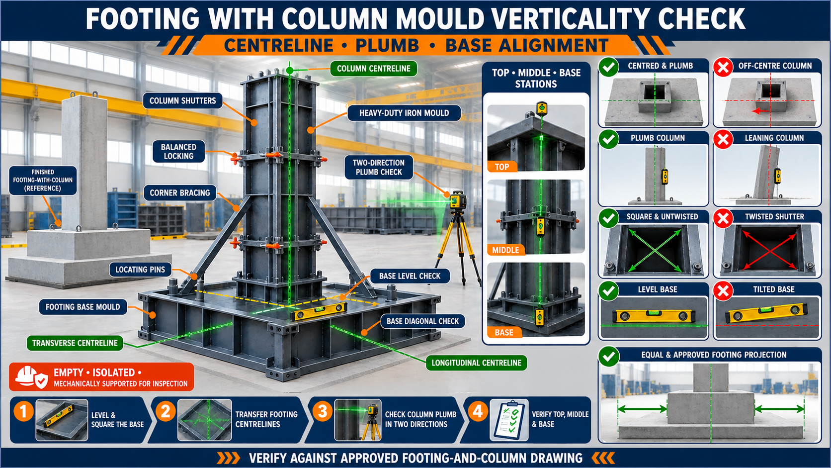
Footing With Column Mould Verticality Check: Centreline, Plumb and Base Alignment Guide
A footing-with-column mould produces the foundation base and column in a single concrete pour. If the column shutter is tilted, twisted or off-centre from the footing, the finished unit may create installation and load-alignment problems. This guide explains centreline transfer, plumb checking and base alignment for heavy-duty iron moulds.
By Paras Steel Industries ·
Footing With Column Mould Verticality Check: Centreline, Plumb and Base Alignment Guide
Footing With Column Mould Verticality Check: Centreline, Plumb and Base Alignment Guide
A footing-with-column mould casts a precast foundation base and vertical column as one monolithic concrete component.
The mould must maintain the correct relationship between the footing base and column. The column centreline should match the specified footing position, and the column shutters should remain plumb and square.
Incorrect alignment can produce a leaning column, unequal footing projections, inconsistent concrete cover and difficulty during site installation.
What Is a Footing With Column Mould?
A footing-with-column mould is a heavy-duty iron or steel mould used to manufacture a complete precast foundation-and-column unit in a single casting cycle.
The mould may include:
• Footing base plate • Footing side shutters • Stepped-foundation formers • Column side shutters • End or top shutters • Corner bracing • Structural stiffeners • Quick locks or clamps • Locating pins • Base-frame supports • Reinforcement-positioning fixtures • Hydraulic or mechanical opening components
The exact configuration depends on the approved foundation design.
What Is Column Verticality?
Verticality describes how accurately the column axis follows the specified vertical direction relative to the footing base.
A column may be:
• Correctly plumb • Tilted in one direction • Tilted diagonally • Twisted • Off-centre while remaining plumb • Centred at the base but displaced at the top
All these conditions require different checks.
What Is Plumb?
Plumb means aligned with the true vertical reference established by gravity or calibrated surveying equipment.
A column shutter may appear straight when viewed from one side but still lean in another direction. Plumb should therefore be checked on at least two perpendicular faces.
Why Verticality Is Important
Correct verticality helps provide:
• Proper column position • Consistent footing projection • Accurate site alignment • Correct reinforcement cover • Uniform column dimensions • Better connection with adjoining components • Reliable stacking and transportation • Reduced corrective work • Repeatable production quality
Final acceptance must follow the approved product and project drawings.
What Is Centreline Alignment?
Centreline alignment establishes the relationship between:
• Footing centreline • Column centreline • Reinforcement-cage centreline • Mould-base centreline • Approved project grid
The column may be centrally positioned or intentionally offset, depending on the design. Centring should not be assumed without checking the drawing.
Base Alignment vs Column Alignment
Base Alignment
Base alignment checks the level, squareness and dimensions of the footing mould.
Column Alignment
Column alignment checks the column’s position, verticality and relationship with the footing.
A correctly plumb column can still be wrong if the footing base is twisted or the column is positioned incorrectly.
Common Alignment Problems
Typical defects include:
• Column leaning • Column shifted sideways • Unequal footing projections • Twisted column shutter • Footing base out of square • Column not perpendicular to base • Incorrect reinforcement cover • Shutter joints opening during casting • Uneven column dimensions • Top face not matching the required position
The mould and finished product should both be inspected.
Causes of Column Misalignment
Column alignment can change because of:
• Incorrect initial assembly • Loose shutter locks • Worn locating pins • Damaged corner braces • Uneven mould supports • Base-frame settlement • Footing mould not level • Distorted column shutters • Reinforcement interference • Uneven concrete placement • Excessive vibration • Hydraulic-cylinder mismatch • Impact during handling • Previous repair distortion • Concrete buildup on contact faces
The root cause should be corrected before the next pour.
Preparing the Mould for Inspection
Before checking verticality:
• Empty and clean the mould • Remove hardened concrete and slurry • Isolate hydraulic equipment • Release stored pressure • Mechanically support movable shutters • Close the mould in its casting position • Secure the base frame • Inspect the foundation • Review the approved drawing • Identify fixed reference datums • Prepare calibrated measuring equipment
Never work between unsupported shutters.
Establishing a Fixed Datum
Verticality and centreline measurements require stable references.
Possible datums include:
• Factory survey benchmark • Mould-base centreline • Footing-cavity centreline • Fixed base-frame point • Verified foundation marker • Machined locating stop • Approved offset line
Do not measure from a shutter that has not been checked.
Marking Footing Centrelines
Transfer the approved longitudinal and transverse centrelines to:
• Mould base • Footing side shutters • Base frame • Column-shutter support • Inspection jigs • Stable external reference points
These lines should intersect at the approved column position.
Marking the Column Centreline
The column centreline can be marked at:
• Column base • Intermediate height • Column top • Opposite shutter faces • Structural support frame
A laser or surveying tool can then compare the column axis with the footing datum.
Checking the Footing Mould Base
Before checking the column, verify the footing base.
Inspect:
• Base-plate level • Longitudinal level • Cross-level • Flatness • Corner elevations • Support contact • Anchor condition • Base-frame twist • Concrete buildup below shutters
A tilted base can produce misleading column readings.
Checking Footing Dimensions
Measure:
• Overall length • Overall width • Step dimensions where specified • Cavity depth • Opposite-side parallelism • Diagonals • Column-offset position • Corner squareness
All dimensions should come from the approved product drawing.
Checking Footing Squareness
Footing squareness may be verified using:
• Diagonal measurements • Approved engineer’s square • Laser lines • Fixed corner templates • Side-to-end shutter comparison
Unequal diagonals may indicate a twisted or parallelogram-shaped base.
Checking Column Position at the Base
The column shutter should be positioned relative to the footing reference lines.
Check:
• Longitudinal centreline • Transverse centreline • Approved offset • Equal or specified footing projections • Shutter contact with the base • Locating-pin engagement • Corner-brace position
Measure from fixed datums rather than from unverified shutter edges.
Checking Column Plumb With a Laser
A laser can provide a visible vertical reference.
A general method includes:
1. Set the Laser on a Stable Surface
Keep it independent of the mould.
2. Verify Calibration
Follow the equipment procedure.
3. Establish the Base Reference
Align with the approved column centreline.
4. Check the Column Bottom
Record the relationship at the base.
5. Check the Column Top
Compare the upper position.
6. Repeat on the Perpendicular Face
Check both directions.
7. Record the Results
Compare with the approved tolerance.
No generic verticality tolerance should be assumed.
Checking Plumb With Survey Equipment
A total station, theodolite or other approved survey equipment can check:
• Column shutter edges • Centreline targets • Top-to-bottom displacement • Diagonal lean • Twist • Relationship with footing datums
Survey targets should be placed consistently and should not move during inspection.
Checking Plumb With a Spirit Level
A suitable calibrated spirit level may provide a practical workshop check.
For reliable use:
• Clean the shutter face • Confirm the surface is suitable • Check more than one height • Check two perpendicular faces • Reverse the level where appropriate • Confirm with another method when required
A local plate bulge can affect the reading.
Using a Plumb Line
A plumb bob may provide a gravity reference where suitable.
Consider:
• Wind or air movement • Stable suspension point • Sufficient clearance • Fixed measurement points • Safe access • Consistent readings
The method should match the required inspection accuracy.
Checking Column Shutter Straightness
A column shutter may be vertical at its ends but bowed through the middle.
Inspect using:
• Verified straightedge • Laser line • Tensioned reference wire • Dial-indicator arrangement • Survey stations • Approved template
Check every forming face.
Checking Column Squareness
For a square or rectangular column, inspect:
• Width at the bottom • Width at the middle • Width at the top • Opposite-side parallelism • Cross-section diagonals • Corner angles • Shutter-joint steps
The column cross-section should remain consistent along its height.
Checking Column Twist
A twisted column shutter can produce a rotated top section.
Twist may be identified by:
• Comparing diagonals at multiple heights • Checking corner centreline positions • Surveying all four edges • Comparing top and bottom cross-sections • Inspecting corner-brace alignment
Do not force the top shutter into position to hide twist below it.
Checking Perpendicularity to the Footing
The column axis should maintain the specified relationship with the footing base.
Check:
• Column plumb • Footing-base level • Column-to-base angle • Centreline intersection • Projection on all sides • Top-position relationship
If the footing is intentionally sloped or specially shaped, follow the approved drawing rather than assuming a right-angle reference.
Inspecting Column-to-Base Joints
The column shutters meet the footing mould at critical joints.
Inspect for:
• Visible gaps • Concrete buildup • Damaged seals • Misaligned edges • Loose fasteners • Cracked welds • Incomplete contact • Incorrect chamfer transitions • Interference from reinforcement
A joint gap can cause slurry leakage and change the column profile at its base.
Inspecting Locating Pins and Stops
Locating components help establish repeatable column position.
Check:
• Pin straightness • Bush wear • Hole enlargement • Stop position • Mounting-bolt security • Cracked welds • Slurry buildup • Complete engagement • Wear marks • Repeatability
Worn locating points may allow the column assembly to shift during vibration.
Inspecting Corner Bracing
Corner braces help maintain the column’s squareness and verticality.
Inspect:
• Brace straightness • Mounting points • Fasteners • Welds • Adjustment mechanisms • Contact with shutter frame • Previous repairs • Signs of movement
A damaged brace may allow the column shutter to rack diagonally.
Inspecting Locks and Clamps
Locks should close column-shutter joints evenly.
Check:
• Wedge surfaces • Screw threads • Toggle pivots • Lock brackets • Pin condition • Alignment • Engagement • Wear • Cracked welds • Concrete buildup
Excessive locking force can distort the shutter.
Balanced Locking Sequence
A general locking process may include:
1. Clean Contact Faces
Remove concrete and slurry.
2. Position the Column Assembly
Seat it against locating pins and stops.
3. Engage Corner Locators
Confirm the base position.
4. Apply Locks Lightly
Engage every lock without fully tightening one side.
5. Check Centreline and Plumb
Correct the position before final tightening.
6. Tighten Progressively
Use a balanced sequence.
7. Recheck Verticality
Confirm the locks did not pull the shutter out of plumb.
8. Inspect Joint Contact
Verify that all forming joints are closed.
The approved mould procedure should determine the final sequence.
Reinforcement-Cage Alignment
The reinforcement cage should follow the column and footing design.
Check:
• Cage centreline • Verticality • Footing reinforcement position • Column bars • Stirrups or ties • Required concrete cover • Spacers • Starter-bar position • Insert clearance where specified • Stability during shutter closure
A misaligned cage can push the column shutters away from their correct position.
Checking Concrete Cover
Concrete cover should be verified around:
• Column faces • Footing sides • Footing base • Column-to-footing junction • Corners • Approved inserts
Requirements should come from the structural drawing.
Do not move shutters to compensate for an incorrectly fabricated cage.
Applying Mould Release Agent
After cleaning and alignment, apply a suitable release agent.
The coating should be:
• Thin • Uniform • Present on all forming surfaces • Applied around the column-base junction • Free from excessive pooling • Kept away from reinforcement • Compatible with the required concrete finish
Release agent should not hide surface damage or buildup.
Pre-Pour Verticality Checklist
Before placing concrete, confirm:
• Correct drawing revision is available • Mould base is level • Footing dimensions are verified • Footing diagonals are correct • Column base position is checked • Column centreline matches the approved location • Column is plumb in two directions • Shutter straightness is checked • Column cross-section is square • Twist is checked • Locating pins are fully engaged • Braces are secure • Locks are progressively tightened • Reinforcement is centred • Concrete cover is verified • Joints are sealed • No tools remain inside the mould
Record the inspection according to the quality plan.
Concrete Placement Sequence
Concrete should be placed in a controlled manner to avoid shifting the reinforcement or column shutters.
Good practices include:
• Fill the footing uniformly • Avoid dumping concrete against one shutter • Maintain balanced levels • Monitor the column base • Place concrete progressively up the column • Keep reinforcement stable • Watch locks and braces • Follow the approved pour sequence
Uneven filling can create lateral pressure and move the column assembly.
Effect of Vibration on Verticality
Vibration may loosen inadequately secured components.
Before vibration:
• Check base supports • Confirm all locks • Inspect corner braces • Verify locating pins • Check reinforcement spacers • Remove loose tools
During vibration, observe for:
• Shutter movement • Lock movement • Joint leakage • Brace vibration • Change in centreline marks • Unusual metallic noise
Stop the process safely if significant movement occurs.
Checking Alignment During Casting
Where the approved procedure provides safe access, monitor external reference marks.
Check:
• Column top position • Brace movement • Lock position • Base-frame movement • Joint gaps • Reinforcement movement
Do not enter pinch zones or climb onto an active mould.
Preparing for Demoulding
Before opening the mould:
• Confirm adequate concrete strength • Support the precast unit • Isolate hydraulic or powered equipment • Release stored pressure • Mechanically secure shutters • Clean concrete around locks • Identify the approved opening sequence • Keep personnel clear of pinch points • Prepare suitable lifting equipment
The lifting arrangement must follow the engineered product-handling procedure.
Correct Demoulding Sequence
A general sequence may include:
1. Support the Concrete Unit
Prevent unexpected movement.
2. Release Secondary Locks
Open non-primary locking points progressively.
3. Support Heavy Shutters
Prevent them from falling.
4. Release Primary Locks
Follow the approved sequence.
5. Separate Column Shutters
Move them away without dragging across concrete edges.
6. Open Footing Shutters
Protect footing corners.
7. Lift or Move the Unit Safely
Use approved lifting points and equipment.
8. Inspect the Finished Product
Check verticality, dimensions and finish.
Do not force a shutter that remains mechanically engaged.
Post-Demoulding Verticality Inspection
Inspect the finished footing-with-column unit for:
• Footing dimensions • Footing diagonals • Base flatness • Column position • Column plumb • Column straightness • Cross-section dimensions • Twist • Concrete cover • Column-to-footing junction • Surface finish • Cracks and edge damage
Use stable supports during inspection.
Checking the Finished Column Centreline
Transfer the footing datums to the finished product.
Compare:
• Column centre at the base • Column centre at the top • Longitudinal offset • Transverse offset • Footing projections • Approved installation reference
The product should be evaluated against the approved drawing.
Troubleshooting Common Problems
Problem: Column Leans in One Direction
Possible causes:
• Shutter was not plumb • Base mould was not level • Brace moved • Concrete placement was uneven • Locks loosened during vibration • Locating pin was worn
Problem: Column Is Plumb but Off-Centre
Possible causes:
• Incorrect datum was used • Column support was positioned wrongly • Offset was misunderstood • Locating stop moved • Footing centreline was marked incorrectly
Problem: Column Is Twisted
Possible causes:
• Corner braces are misaligned • Opposite locks were tightened unevenly • Shutter frame is distorted • Top and bottom cross-sections were not aligned • Previous repair introduced twist
Problem: Unequal Footing Projection
Possible causes:
• Column is off-centre • Footing shutters are misaligned • Footing cavity is out of square • Wrong reference edge was used • Base frame moved
Problem: Slurry Leaks at the Column Base
Possible causes:
• Column-to-footing joint gap • Concrete buildup • Damaged seal • Uneven locks • Shutter misalignment • Reinforcement interference
Problem: Column Thickness Varies
Possible causes:
• Shutter is bowed • Opposite faces are not parallel • Locks are uneven • Concrete pressure moved the shutter • Stiffener is damaged
Problem: Finished Unit Rocks on Its Base
Possible causes:
• Footing base is not flat • Concrete fins remain • Mould base is distorted • Product is supported incorrectly • Uneven finishing occurred
Correcting Mould Alignment
A controlled correction may involve:
• Cleaning contact surfaces • Levelling the base frame • Replacing worn pins and bushes • Adjusting approved locating stops • Repairing corner braces • Correcting shutter straightness • Rechecking hydraulic movement • Repairing support brackets • Inspecting the foundation • Repeating the complete survey
Do not use random packing or excessive locking force to force the mould into alignment.
Mould Maintenance Checklist
After every production cycle:
• Clean footing and column forming surfaces • Remove slurry from joints • Inspect locating pins • Check corner braces • Inspect locks and clamps • Check base supports • Examine welds and stiffeners • Verify shutter straightness • Check hydraulic components where fitted • Inspect seals • Confirm smooth opening and closing • Apply corrosion protection during storage • Record recurring verticality defects
Maintenance records help identify gradual alignment changes.
Benefits of Correct Verticality Setup
Accurate setup provides:
• Plumb precast columns • Correct footing relationship • Consistent footing projections • Better reinforcement-cover control • Accurate installation geometry • Cleaner column-base joints • Reduced corrective work • Lower rejection • Repeatable production • Longer mould service life
Conclusion
A footing-with-column mould must control the base geometry and vertical column position as one complete system. The footing base should be level and square, while the column shutters should remain centred, plumb, straight and free from twist.
Reliable inspection requires fixed mould datums, centreline transfer, plumb checks in two directions, diagonal measurements and verification of the column-to-footing joint. Locating pins, corner braces, locks and reinforcement clearance should also be inspected before concrete casting.
A correctly aligned heavy-duty iron footing-with-column mould helps manufacturers produce monolithic precast foundation units with accurate geometry and dependable site installation.