
Precast Mould Maintenance Guide
Fencing Pole Mould Wire-Hole Pin Withdrawal: Concrete Sticking, Edge Breakage and Safe Removal Guide
Wire-hole pins create accurate openings in precast fencing poles for installing fencing wire. However, incorrect pin withdrawal can cause concrete sticking, damaged hole edges, bent pins and production delays. This guide explains pin preparation, correct removal sequence, common problems and essential maintenance practices for heavy-duty iron fencing pole moulds.
By Paras Steel Industries ·
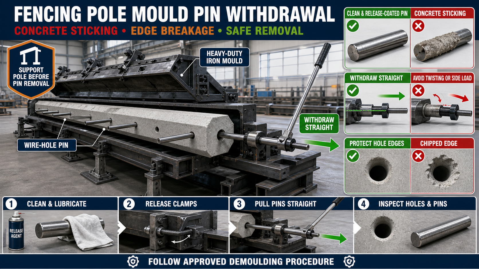
Fencing Pole Mould Wire-Hole Pin Withdrawal: Concrete Sticking, Edge Breakage and Safe Removal Guide
Fencing Pole Mould Wire-Hole Pin Withdrawal: Concrete Sticking, Edge Breakage and Safe Removal Guide
Wire-hole pins are small but important components of a fencing pole mould. They create accurately positioned holes through which fencing wire can be installed after the concrete pole is erected.
If these pins are dirty, misaligned or removed incorrectly, they may stick inside the concrete. Excessive pulling, twisting or hammering can then damage the hole edges, bend the pins or crack the precast pole.
A controlled withdrawal procedure improves product quality, protects the iron mould and reduces production downtime.
What Is a Wire-Hole Pin System?
A wire-hole pin system consists of removable iron or steel pins installed across the fencing pole mould at specified positions. During casting, the pins reserve openings inside the concrete pole.
The system may include:
• Removable steel pins • Pin-supporting holes or bushes • External handles or threaded pulling arrangements • Alignment plates or guides • Pin locks or retaining devices
Pin diameter, quantity and spacing should be selected according to the fencing pole design and project requirements.
Why Do Wire-Hole Pins Stick in Concrete?
Concrete sticking usually occurs when the pin surface develops excessive bonding or withdrawal resistance.
Common causes include:
• Release agent was not applied properly • Old concrete slurry remained on the pin • The pin surface was rough, rusty or damaged • Concrete entered the pin-support gap • The pin was bent or installed at an angle • The pin was removed after excessive concrete hardening • Concrete mix entered scratches or grooves on the pin • The pin-support bushes were misaligned • The mould or pole moved during withdrawal
The operator should identify the reason for sticking instead of applying uncontrolled force.
How to Prepare Pins Before Concrete Casting
Correct preparation begins before the reinforcement cage and concrete are placed inside the mould.
Clean Every Pin
Remove concrete slurry, cement paste, rust and hardened deposits from the complete pin surface. A clean and smooth pin requires less withdrawal force.
Inspect the Pin Surface
Check every pin for:
• Bending • Deep scratches • Flattened areas • Worn threads • Mushroomed ends • Corrosion or roughness
A damaged pin should be repaired or replaced before casting.
Apply a Suitable Release Agent
Apply a thin and uniform coat of mould release agent to the pin. Excessive oil should be avoided because it may contaminate the surrounding concrete or affect the finish.
Check Pin Alignment
Insert each pin through its supporting holes or bushes and confirm that it moves along a straight path. The pin should not require heavy force during installation.
Verify Reinforcement Clearance
The reinforcement cage must not obstruct the pin. Contact between the pin and reinforcement can make installation and withdrawal difficult.
Correct Wire-Hole Pin Withdrawal Procedure
The following general sequence can help reduce sticking and edge damage. The actual procedure should always follow the mould design and approved factory instructions.
1. Confirm Safe Demoulding Condition
Check that the concrete has developed sufficient strength for pin removal and demoulding. The correct timing depends on the concrete mix, curing method, product design and factory conditions.
2. Support the Concrete Pole
Ensure that the pole remains fully supported inside the mould. It should not shift, rotate or lift while the pins are being removed.
3. Release Pin Locks
Remove locking plates, nuts, wedges or retaining arrangements without disturbing the mould alignment.
4. Remove Surface Slurry
Clean hardened slurry from the exposed pin ends and surrounding guide areas. Slurry buildup can increase withdrawal resistance.
5. Apply Controlled Initial Movement
Start with a small, controlled axial movement to break the bond between the pin and concrete. Do not bend the handle sideways.
6. Withdraw the Pin Straight
Pull the pin along its own centreline. A suitable mechanical pulling arrangement can be used when specified by the mould manufacturer.
7. Support Long Pins During Removal
Long pins should be supported while being withdrawn. Allowing a pin to drop can damage its surface or chip the concrete hole.
8. Inspect the Concrete Opening
Check the finished hole for edge breakage, cracking, blockage or misalignment.
9. Clean the Removed Pin Immediately
Remove fresh cement paste before it hardens. Clean pins are easier to inspect and prepare for the next casting cycle.
How to Prevent Concrete Edge Breakage
Edge breakage commonly occurs when concrete around the hole has insufficient strength or the pin is pulled at an angle.
To protect the hole edges:
• Do not remove pins before the concrete has adequate strength • Keep the pole stable and properly supported • Pull every pin in a straight line • Avoid sudden jerks and uncontrolled hammering • Remove slurry from the pin guide before pulling • Keep pins smooth and properly release-coated • Correct bent pins and misaligned bushes • Avoid twisting unless the mould’s approved mechanism specifically requires it • Inspect hole locations for adequate reinforcement clearance • Maintain proper concrete compaction around every pin
If repeated breakage occurs at the same location, check the pin position, reinforcement arrangement, concrete compaction and mould alignment.
What to Do When a Pin Is Stuck
A stuck pin should not be forced immediately.
First, check whether:
• The locking device has been completely released • Hardened slurry is blocking the external guide • The pole is placing side pressure on the pin • The pin is bent • The mould shutter has shifted • The pulling tool is aligned with the pin axis
Use a controlled mechanical puller where appropriate. The pulling force should remain centred on the pin.
Avoid striking the concrete pole or applying heavy sideways force. These actions can enlarge the opening, break the edge or create hidden cracks.
Common Pin-Removal Mistakes
Pulling at an Angle
Side loading causes the pin to press against the concrete opening. This increases friction and may break the hole edge.
Using Excessive Hammering
Heavy hammering can deform pin ends, damage threads and transfer shock into the concrete pole.
Removing Pins Too Early
Concrete with insufficient strength may crumble around the openings.
Removing Pins Too Late
Extended concrete contact can increase bonding, particularly when release-agent coverage is poor.
Ignoring Slurry Buildup
Hardened slurry around guide bushes reduces clearance and causes pin jamming.
Using Bent Pins
A bent pin cannot move smoothly through aligned supports and may produce incorrectly positioned holes.
Applying Too Much Release Agent
Excessive release agent may stain the concrete or collect contaminants. Use a controlled and uniform coating.
Wire-Hole Pin Maintenance Checklist
After every production cycle:
• Clean every pin completely • Inspect the pin for bending and surface damage • Check threaded portions and pulling handles • Clean the mould’s pin-support holes and bushes • Confirm smooth pin movement • Inspect locks and retaining arrangements • Apply corrosion protection during extended storage • Store pins on a straight supporting rack • Replace severely worn or damaged components
Pins should not be thrown onto the floor because impact can bend them or damage their ends.
Checking Pin and Hole Alignment
Correct alignment ensures that fencing wire can pass smoothly through the finished pole.
Before casting, verify:
• Pin centreline matches the mould drawings • Corresponding guide holes are aligned • Pins remain perpendicular to the required pole face • Reinforcement does not push the pins out of position • Locking arrangements hold every pin securely • Mould shutters close without applying side pressure to the pins
A simple inspection jig can help maintain consistent hole spacing during repeated production.
Importance of Concrete Compaction Around Pins
Poor compaction can leave voids and weak edges around the wire holes. Excessive vibration or incorrect vibrator placement may also disturb the pins.
During casting:
• Place concrete evenly around the pins • Prevent large aggregate from blocking narrow areas • Keep the pins securely locked • Use controlled vibration • Avoid direct impact between vibration equipment and pins • Inspect for pin movement before completing the pour
The objective is dense concrete around each opening without changing the pin position.
Safety Precautions During Pin Withdrawal
Pin removal creates pulling force and possible pinch points. Operators should follow the plant’s approved safety procedure.
Important precautions include:
• Isolate relevant powered equipment before maintenance or adjustment • Support the mould and concrete pole securely • Keep hands away from pulling mechanisms and pinch points • Use suitable gloves and eye protection • Inspect pulling tools before use • Do not stand directly in the pin’s withdrawal path • Do not use damaged handles or improvised extensions • Keep the work area clean and free from slurry
Only trained personnel should operate hydraulic or mechanical pin-pulling systems.
Benefits of Correct Pin Withdrawal
A proper wire-hole pin withdrawal system provides:
• Cleaner and more accurate holes • Reduced concrete edge breakage • Lower risk of pole cracking • Longer pin and mould service life • Faster demoulding cycles • Fewer rejected fencing poles • Consistent fencing-wire alignment • Reduced repair and maintenance costs
Selecting a Fencing Pole Mould
When purchasing an iron fencing pole mould, evaluate the complete pin system rather than only the main mould body.
Important points include:
• Required pole size and profile • Number and location of wire holes • Pin material and surface finish • Pin-support bush design • Withdrawal mechanism • Locking and alignment arrangement • Accessibility for cleaning • Availability of replacement pins • Mould shutter stiffness and alignment • Manufacturer support and maintenance guidance
The final design should match the fencing pole drawing and intended production process.
Conclusion
Safe fencing pole mould wire-hole pin withdrawal depends on clean pins, proper release-agent application, accurate alignment, adequate concrete strength and controlled straight-line removal.
Operators should never use excessive side force or uncontrolled hammering to free a stuck pin. Regular cleaning and inspection of pins, bushes, locks and mould alignment can prevent concrete sticking, edge breakage and production delays.
A well-maintained heavy-duty iron fencing pole mould helps manufacturers produce strong precast poles with clean, accurately positioned wire holes and consistent quality.