
Precast Pole Mould Guide
Fencing Pole Mould Hole-Pin System: Spacing, Alignment and Maintenance Guide
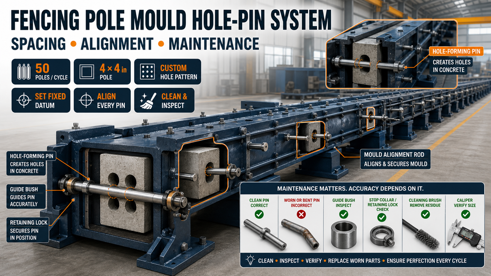
Hole-forming pins create accurately positioned openings in precast fencing poles for fencing wire and project connections. This guide explains custom hole spacing, pin alignment, casting preparation, demoulding and maintenance.
By Paras Steel Industries ·
Fencing Pole Mould Hole-Pin System: Spacing, Alignment and Maintenance Guide
Fencing Pole Mould Hole-Pin System: Spacing, Alignment and Maintenance Guide
Precast concrete fencing poles often require multiple holes along their length. These openings may be used for installing fencing wire, barbed wire, connecting hardware or another project-specific fencing system.
A hole-pin arrangement inside a heavy-duty steel fencing pole mould creates these openings during concrete casting. Correctly positioned pins reduce the need for drilling hardened concrete after production.
The Fencing Pole Mould manufactured by Paras Steel Industries supports custom pole lengths, hole-placement arrangements and taper requirements. Its standard production line can manufacture up to 50 fencing poles in one casting cycle.
Because one line produces several poles simultaneously, a small error in the pin-setting system can be repeated throughout the complete batch. Hole spacing, alignment and maintenance must therefore be controlled carefully.
Fencing Pole Mould Specifications
The standard product configuration listed by Paras Steel Industries includes:
Mould category: Precast concrete fencing pole mould
Production capacity: 50 poles per production line or batch
Standard cross-section: 4 in x 4 in or 100 mm x 100 mm
Pole length: Customisable according to project requirements
Hole pattern: Customisable according to project requirements
Main supporting frame: 50 x 100 mm heavy C-channel
Side and base plates: 4 mm to 6 mm high-grade steel plates
Reinforcement structure: 50 x 50 x 6 mm structural steel angle
Alignment rods and locks: Heavy-duty bright steel bar
Operating system: Manual or hydraulic compatible
What Is a Hole-Pin System?
A hole-pin system uses accurately positioned removable or mould-integrated pins to form openings in fresh concrete.
Concrete is poured around the pins. After the concrete reaches the appropriate stage and the pins are released according to the mould design, the finished pole contains the required holes.
A complete pin arrangement may include:
• Hole-forming pin • Pin holder • Positioning bracket • Lock or retaining device • Stop collar • Guide bush • Sealing arrangement • Alignment template • Handle or extraction arrangement
The exact design depends on hole diameter, pole size, reinforcement position and production system.
Hole-Forming Pins vs Mould Alignment Pins
These components perform different functions and should not be confused.
Hole-Forming Pins
Hole-forming pins create openings in the finished concrete pole.
Their position determines:
• Distance between holes • Distance from pole ends • Hole diameter • Hole direction • Alignment through the pole
Mould Alignment Pins
Mould alignment pins help position and lock the steel shutters or mould sections.
The Paras Steel Industries fencing pole mould uses heavy-duty bright steel bars for alignment rods and locks.
Mould alignment pins control mould closure, while hole-forming pins control the openings in the concrete product.
Why Accurate Hole Spacing Is Important
Correct hole spacing helps:
• Maintain a straight fencing-wire line • Simplify installation • Reduce site drilling • Keep adjacent poles compatible • Maintain uniform fence height • Improve finished appearance • Reduce wire tension variation • Prevent weak or damaged pole sections • Meet project drawings • Improve batch consistency
Incorrect hole placement can make otherwise acceptable poles difficult to install.
How Is Hole Spacing Determined?
Hole spacing should be taken from the approved fencing-pole drawing.
The pattern may depend on:
• Pole length • Number of fencing-wire rows • Fence height • Wire type • Barbed-wire arrangement • Ground embedment depth • Top clearance • Bottom clearance • Project-security requirement • Connection system
There is no universal hole spacing suitable for every project.
Before manufacturing the mould, the customer should confirm:
• Total pole length • Pole cross-section • Number of holes • Hole diameter • Centre-to-centre spacing • Distance of first hole from the top • Distance of last hole from the bottom • Hole orientation • Required taper • Reinforcement layout
Hole-Pattern Reference Points
All hole positions should be measured from one defined datum or reference point.
Possible reference points include:
• Top end of pole • Bottom end of pole • Fixed end plate • Mould base reference • Approved centreline
Measuring every new hole from the previous hole can accumulate error along the pole.
A fixed datum improves repeatability across all 50 mould cavities.
Hole Diameter
The pin diameter generally determines the basic opening size, subject to the pin shape, concrete behaviour and production tolerance.
Hole diameter should provide the required clearance without unnecessarily weakening the concrete section.
Consider:
• Wire diameter • Hook or connector dimensions • Installation clearance • Concrete cover • Reinforcement position • Pole cross-section • Project tolerance
The pin size should be specified before mould fabrication.
Pin Taper
A slight engineered taper may help some pins release from concrete more easily.
However, excessive taper can create an opening with significantly different diameters on opposite sides.
Pin geometry should be designed according to:
• Required finished opening • Withdrawal direction • Concrete strength during removal • Mould-opening sequence • Surface-finish requirement
Do not grind or modify a production pin without checking the finished-hole requirement.
Hole Direction and Orientation
Hole-forming pins must follow the required direction through the pole.
Possible arrangements include:
• Holes passing completely through the pole • Holes on one selected face • Alternating hole directions • Project-specific connection openings
Pins installed at an angle can create misaligned openings and reduce installation accuracy.
Use a suitable guide, bracket or bush to maintain the correct direction.
Relationship Between Pins and Reinforcement
Hole-forming pins must not clash with the reinforcement cage.
Before finalising the mould, coordinate:
• Main longitudinal bars • Stirrups or links • Concrete cover • Hole positions • Lifting points • Pole end details
Cutting or moving reinforcement to accommodate a pin should not be done without approval from the responsible technical professional.
If the hole pattern conflicts with the reinforcement, revise the approved design before production.
Setting Pins Across a 50-Pole Line
A high-capacity line requires a repeatable setting method.
A practical sequence may include:
1. Identify every pole cavity. 2. Clean pin holders and guide bushes. 3. Establish the fixed reference datum. 4. Install a calibrated positioning template. 5. Insert pins in the correct sequence. 6. Engage every stop or retaining lock. 7. Check pin projection. 8. Verify pin direction. 9. Compare corresponding pins across cavities. 10. Record the inspection.
Numbering cavities makes it easier to identify repeated defects.
Using a Hole-Spacing Template
A reusable template can improve speed and consistency.
The template may show:
• Pole end reference • Hole centre locations • Pin diameter • Number of pins • Orientation • Cavity identification
The template should be checked periodically for bending, wear and dimensional accuracy.
Do not rely only on visual estimation.
Checking Pin Alignment
Pin alignment should be checked in multiple directions.
Longitudinal Alignment
Confirm that all hole centres follow the required line along the pole length.
Crosswise Alignment
For through-holes, confirm that pins enter and exit at the correct corresponding locations.
Vertical or Horizontal Orientation
Confirm the specified orientation relative to the pole faces.
Projection
Check that every pin enters the cavity to the required depth.
Secure Locking
The pin should not move during reinforcement placement, concrete pouring or vibration.
Tools for Pin Inspection
Useful inspection tools may include:
• Steel measuring tape • Steel rule • Vernier caliper • Engineer’s square • Straightedge • String line • Laser reference • Pin-setting template • Go/no-go gauge • Depth gauge
Measuring tools should be suitable for the required accuracy and maintained properly.
Preparing the Mould for Casting
1. Clean the Steel Mould
Remove hardened concrete, rust and production residue from:
• Casting plates • Cavity bottoms • Pin holders • Guide bushes • Locks • Alignment rods • End plates
2. Inspect the Pins
Check every hole-forming pin for:
• Bending • Wear • Concrete buildup • Corrosion • Damaged taper • Worn stop collar • Loose handle • Damaged threads • Incorrect diameter
3. Check Mould Alignment
Verify the main mould line, cavities, end plates, locks and bright-steel alignment rods.
4. Apply Release Agent
Apply a thin and uniform layer of suitable release agent to the mould surface.
Where the production procedure permits, apply the appropriate material to the hole-forming pins to support clean removal.
Avoid excessive application because it can stain concrete or contaminate reinforcement.
5. Install Reinforcement
Position the approved reinforcement cage using suitable cover blocks and spacers.
Confirm that the reinforcement does not contact the mould or hole-forming pins.
6. Install and Lock Pins
Insert every pin to its defined stop position and engage its retaining system.
7. Complete a Pre-Pour Inspection
Check every cavity before concrete placement.
Pre-Pour Hole-Pin Checklist
Confirm:
• Correct pole drawing selected • Correct pin diameter installed • Correct number of pins • First-hole position correct • Last-hole position correct • Centre-to-centre spacing correct • Pin direction correct • Pin projection correct • Retaining locks engaged • Reinforcement clear of pins • Mould shutters fully locked • All 50 cavities inspected • Defective pins replaced
Concrete Casting and Vibration
Concrete should be placed in a controlled sequence throughout the mould line.
During casting:
• Prevent direct impact on the pins • Monitor pin movement • Maintain consistent concrete workability • Fill cavities uniformly • Control vibration duration • Observe locks and shutters • Watch for slurry leakage around pin openings
Excessive vibration may loosen pins or allow cement slurry to escape around the pin holders.
Insufficient vibration can create honeycombing near the hole.
Preventing Slurry Leakage Around Pins
Leakage around a pin can create damaged hole edges and loss of cement paste.
Possible causes include:
• Worn guide bush • Incorrect pin diameter • Damaged seal • Loose retaining device • Bent pin • Dirty contact surface • Excessive vibration • Enlarged holder opening
Correct the mechanical cause instead of repeatedly covering the area with temporary sealing material.
When Should Pins Be Removed?
Pin-removal timing depends on:
• Concrete mix • Pin design • Release arrangement • Concrete temperature • Curing method • Required edge stability • Mould-opening sequence
Removing a pin too early may deform the hole. Removing it too late may make extraction difficult and damage the concrete edge.
The correct timing should be established during controlled trial production and documented in the operating procedure.
Pin Removal Process
A general removal process may include:
1. Confirm the approved production stage. 2. Release the pin-retaining mechanism. 3. Clear concrete residue from the accessible end. 4. Rotate the pin only if the mould design permits. 5. Pull the pin in its designed direction. 6. Apply force gradually. 7. Stop if the pin binds. 8. Inspect the formed hole. 9. Clean the removed pin immediately. 10. Store it in the assigned rack.
Do not hammer pins sideways because this can enlarge the hole, bend the pin or damage the steel holder.
Hydraulic Pin Extraction
Some high-output systems may use hydraulic assistance for selected mould movements or pin extraction.
A hydraulic arrangement should provide:
• Controlled straight-line force • Correct pin gripping • Suitable stroke • Pressure control • Stable mounting • Safe operator position
Hydraulic force should not be used to pull a pin at an angle or overcome an unresolved obstruction.
Inspecting Finished Holes
After demoulding, check:
• Hole count • Hole diameter • Centre position • Spacing • Direction • Edge quality • Concrete compaction • Reinforcement exposure • Cracks • Slurry-loss marks • Compatibility with the intended wire or connector
A simple approved gauge can quickly verify whether the opening is clear.
Record defects by mould-cavity number and pin position.
Common Hole-Pin Defects
Hole in the Wrong Position
Possible causes:
• Incorrect template • Wrong reference point • Loose pin bracket • Operator setting error
Angled Hole
Possible causes:
• Bent pin • Worn guide bush • Misaligned holder • Reinforcement interference
Oversized Hole
Possible causes:
• Worn pin holder • Excessive pin movement • Sideways removal • Incorrect pin taper
Blocked or Partially Formed Hole
Possible causes:
• Pin not inserted fully • Pin moved during casting • Concrete entered a damaged holder • Incorrect extraction
Broken Hole Edge
Possible causes:
• Early pin removal • Late or forced extraction • Inadequate release preparation • Weak concrete • Poor compaction
Cracks Around Hole
Possible causes:
• Hole too close to pole edge • Reinforcement conflict • Excessive extraction force • Premature demoulding • Incorrect product design
Daily Pin Maintenance
After every casting cycle:
• Remove concrete residue • Clean pin surfaces • Check straightness • Inspect taper and diameter • Clean guide bushes • Check stop collars • Inspect retaining locks • Apply suitable protection where required • Store pins in a rack • Record damaged positions
Do not throw pins on the floor because impact can bend them.
Periodic Maintenance
At planned intervals:
• Measure pin diameter • Check pins using a straightedge • Inspect holder alignment • Inspect guide-bush wear • Tighten mounting brackets • Verify the hole template • Check cavity reference marks • Inspect bright-steel mould-alignment rods • Repair slurry-leakage points • Replace damaged pins as a matched specification
Pin Storage
Provide a dedicated rack with identification for:
• Pin diameter • Hole pattern • Pole length • Product drawing • Cavity position where relevant
Separating different pin sizes prevents incorrect installation.
Maintenance of the Complete Mould
The hole-pin system depends on the overall accuracy of the fencing pole mould.
Inspect:
• 50 x 100 mm main C-channels • 4 mm to 6 mm steel plates • 50 x 50 x 6 mm structural angles • Bright-bar alignment rods • Locks and clamps • Hydraulic components • Cavity dimensions • End plates • Welded joints
A twisted or misaligned mould can disturb hole position even when the individual pins are accurate.
Buying Checklist
Before ordering a fencing pole mould, share:
• Pole length • 4 x 4 inch or custom cross-section • Required line capacity • Number of holes per pole • Hole diameter • Centre-to-centre spacing • First-hole distance • Last-hole distance • Hole direction • Pole taper • Reinforcement drawing • Manual or hydraulic preference • Required daily production • Vibration method
Final Conclusion
A properly designed hole-pin system produces accurate openings in precast concrete fencing poles and reduces drilling work at the project site.
The pin layout should be based on a fixed reference point and approved product drawing. Diameter, spacing, projection, orientation and reinforcement clearance must be checked before every casting cycle.
Regular cleaning and inspection prevent bent pins, worn guide bushes, slurry leakage and damaged concrete edges.
Paras Steel Industries manufactures heavy-duty steel Fencing Pole Mould lines with a production capacity of up to 50 poles per casting cycle.
The standard mould supports a 4 x 4 inch or 100 x 100 mm pole cross-section and uses 50 x 100 mm heavy C-channels, 4 mm to 6 mm steel plates, 50 x 50 x 6 mm structural angles and heavy-duty bright-steel alignment rods.
Pole length, hole placement and taper can be customised according to the project requirement.
For specifications and pricing, share your pole drawing, required length, hole diameter, complete hole-spacing pattern, daily production target and preferred manual or hydraulic system with Paras Steel Industries.