
Precast Mould Guide
Embossed Wall Panel Mould Liner Changeover: Pattern Matching, Fastening and Cleaning Guide
An accurate mould-liner changeover helps produce consistent embossed wall panels without pattern mismatch, joint lines or slurry leakage. This guide explains liner identification, fixed-datum positioning, fastening, cleaning and final inspection.
By Paras Steel Industries ·
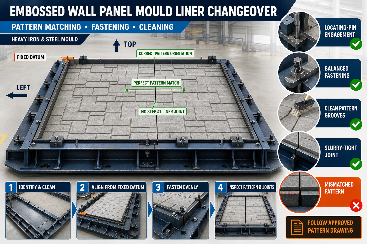
Embossed Wall Panel Mould Liner Changeover: Pattern Matching, Fastening and Cleaning Guide
Embossed Wall Panel Mould Liner Changeover Guide
Embossed precast wall panels are used for compound walls, industrial boundaries, housing projects, highways and architectural applications. Their finished appearance depends directly on the accuracy and cleanliness of the pattern-forming mould liner.
An incorrectly positioned liner can create broken patterns, visible joint lines, uneven borders or dimensional differences between panels. Loose fasteners may also allow concrete slurry to enter beneath the liner and damage the finished surface.
This guide explains embossed wall panel mould liner changeover, including pattern identification, fixed-datum positioning, joint matching, fastening, cleaning and pre-casting inspection.
What Is an Embossed Wall Panel Mould Liner?
A mould liner is a patterned insert installed inside a heavy-duty iron or structural-steel wall panel mould. Its surface transfers the required texture or design onto fresh concrete.
Depending on the approved mould design, a liner may be:
• Removable • Interchangeable • Bolted • Clamped • Pinned • Sectional • Integrated with an iron backing plate • Custom-made for a particular pattern
The liner material, thickness and fastening arrangement should follow the approved mould drawing.
Why Liner Changeover Accuracy Is Important
A liner changeover may be required when:
• Changing the panel design • Replacing a damaged liner • Producing a different pattern • Cleaning behind the liner • Repairing fasteners • Correcting pattern alignment • Servicing the mould surface
Accurate changeover helps achieve:
• Continuous embossed patterns • Uniform pattern depth • Straight panel borders • Correct pattern orientation • Reduced slurry leakage • Easier demoulding • Consistent surface finish • Repeatable production quality • Reduced panel rejection • Longer mould and liner life
Safety Before Liner Removal
Large iron-backed liners can be heavy and difficult to handle.
Before beginning:
1. Stop mould production. 2. Remove all concrete and production materials. 3. Isolate hydraulic or mechanical systems. 4. Apply the plant’s lockout procedure where required. 5. Confirm the liner weight. 6. Inspect the approved lifting arrangement. 7. Clear the handling area. 8. Support the liner before releasing fasteners. 9. Keep workers away from suspended components. 10. Wear suitable personal protective equipment.
Do not use random holes, clamps or pattern projections as lifting points.
Identify the Existing Liner
Before removing the liner, record:
• Pattern name or identification number • Top and bottom orientation • Left and right direction • Mould position • Panel type • Fastener locations • Spacer positions • Joint arrangement • Previous repair areas • Production history where available
Clear identification helps prevent the replacement liner from being installed backwards or in the wrong mould.
Mark Liner Orientation
Some embossed patterns may look similar when viewed separately but will not align if rotated.
Use clear and permanent identification for:
• Top • Bottom • Casting face • Back face • Left edge • Right edge • Datum corner • Mould number
Do not mark the active pattern surface using a method that could transfer onto concrete.
Document the Existing Setup
Before disassembly, take reference photographs or prepare an inspection record showing:
• Liner position • Joint locations • Fastener sequence • Spacer arrangement • Border alignment • Datum point • Sealing method • Lifting arrangement
This record can help operators reinstall the liner correctly.
Remove Hardened Concrete and Slurry
Concrete buildup may hide bolts, pins and liner joints.
Clean:
• Fastener heads • Liner borders • Joint lines • Locating pins • Clamping points • Lifting points • Mould corners • Drainage or vent details where provided
Use non-damaging cleaning tools. Avoid striking pattern details with a steel hammer.
Support the Liner Before Unfastening
A liner may move suddenly after its final fastener is removed.
Before releasing fasteners:
• Attach the approved lifting equipment • Take up the liner weight gradually • Confirm balanced support • Install temporary restraints where required • Keep hands away from pinch points • Check that the liner cannot fall into the mould • Release fasteners in a controlled sequence
Never stand beneath a suspended liner.
Controlled Fastener Removal
Fasteners should be released gradually and evenly.
A practical sequence is:
1. Clean every fastener. 2. Mark its position if different types are used. 3. Loosen opposing fasteners gradually. 4. Keep temporary fasteners engaged. 5. Support the liner continuously. 6. Remove the remaining fasteners. 7. Separate the liner without prying against the pattern. 8. Lift it slowly from the mould. 9. Place it on a stable padded support.
The exact removal sequence should follow the mould design.
Inspect the Removed Liner
After removal, inspect:
• Pattern-face condition • Cracks • Dents • Bent backing plates • Worn pattern details • Damaged edges • Distorted bolt holes • Loose welded studs • Corrosion • Concrete buildup • Previous repairs • Lifting points
A damaged liner should be repaired and checked before reuse.
Correct Liner Storage
Store removed liners so that the pattern face does not carry the liner’s weight.
Recommended practices include:
• Use a stable storage rack • Support the liner at designed points • Protect the embossed face • Keep identification visible • Prevent contact with soil and water • Avoid stacking incompatible patterns • Secure liners against falling • Apply suitable corrosion protection • Keep fastening parts organised
Long liners should be supported adequately to prevent bending.
Clean the Iron Mould Backing Surface
Once the liner is removed, clean the mould surface behind it.
Remove:
• Hardened slurry • Loose rust • Grease buildup • Damaged seal material • Metal burrs • Dirt around bolt holes • Concrete trapped in corners • Loose fasteners
The backing surface must be clean and stable before installing another liner.
Inspect the Mould Structure
Check the heavy iron mould for:
• Backing-plate flatness • Base-frame distortion • Cracked welds • Loose stiffeners • Damaged flange edges • Bent locating pins • Enlarged bolt holes • Corrosion • Misaligned border shutters • Damaged locking points
Installing a straight liner onto a distorted mould will not produce an accurate panel.
Check the Replacement Liner
Before installation, confirm:
• Correct pattern • Correct mould size • Top and bottom orientation • Left and right direction • Matching fastener locations • Border profile • Joint configuration • Liner straightness • Clean pattern surface • Undamaged lifting points
Compare the liner with the approved drawing and identification record.
Establish a Fixed Datum
A fixed datum provides one reference corner or edge for liner positioning.
The datum may be:
• One mould corner • A machined stop • A locating pin • A fixed border edge • A marked centreline • An approved alignment rail
Position the liner from this fixed datum rather than centring it only by visual judgement.
Pattern Matching
Pattern matching is especially important when multiple liner sections form one panel design.
Check:
• Pattern direction • Repeating design sequence • Horizontal continuity • Vertical continuity • Border alignment • Joint location • Pattern depth at the joint • Relationship with neighbouring panels • Top and bottom orientation
Use a reference panel, approved drawing or pattern template where required.
Dry-Fit the Liner
Before final fastening, place the liner inside the mould without fully tightening it.
During dry fitting:
1. Align the datum corner. 2. Engage locating pins. 3. Check all outside borders. 4. Match sectional liner joints. 5. Inspect fastener-hole alignment. 6. Confirm pattern orientation. 7. Check for rocking or unsupported areas. 8. Verify clearance around shutters. 9. Correct the position before tightening.
Do not force bolts into misaligned holes.
Check Liner Flatness
A liner must remain in full contact with its backing surface. Unsupported areas can flex under concrete pressure.
Check for:
• Rocking • Local gaps • High points • Bent edges • Trapped debris • Uneven spacer thickness • Distorted backing plate • Poor joint support
Use a suitable straightedge, gauge or approved inspection method.
Sectional Liner Joint Alignment
Where two or more liner sections meet, the joint must not interrupt the pattern.
Inspect:
• Edge-to-edge contact • Pattern continuity • Joint level • Gaps • Step between surfaces • Border-line alignment • Fastener positions • Support beneath the joint
A step at the liner joint can appear as a visible line or ridge on the concrete panel.
Liner Fastening Sequence
Fasten the liner gradually to avoid pulling it out of position.
A suitable process is:
1. Install all fasteners loosely. 2. Confirm the fixed datum. 3. Align the outer border. 4. Match sectional joints. 5. Tighten central fasteners lightly. 6. Work outward in a balanced sequence. 7. Tighten opposing fasteners gradually. 8. Recheck pattern alignment. 9. Inspect liner flatness. 10. Complete final tightening.
Follow the approved fastener-tightening requirement.
Avoid Over-Tightening
Excessive tightening can:
• Distort the liner • Damage bolt holes • Pull the pattern out of alignment • Create local depressions • Damage seals • Bend the iron backing plate • Make future removal difficult
Fasteners should secure the liner without deforming it.
Inspect Fasteners and Clamps
Before reuse, check:
• Bolt threads • Nuts • Washers • Clamps • Locking plates • Welded studs • Locating pins • Retaining brackets • Corrosion • Deformation
Replace damaged components with approved matching parts.
Slurry Control Around the Liner
Concrete slurry may enter through liner joints, borders or fastener holes.
Common leakage points include:
• Sectional joints • Outer border • Corners • Bolt penetrations • Damaged seals • Misaligned surfaces • Pattern intersections • Repair areas
Leakage beneath the liner can lift it, create surface marks and make removal difficult.
Seal Inspection
Where the mould design uses sealing strips or gaskets, inspect for:
• Cuts • Cracks • Flattening • Hardening • Missing sections • Incorrect positioning • Concrete contamination • Uneven compression • Oil damage
Use only sealing material compatible with the mould and concrete-production process.
Do Not Use Excessive Temporary Sealant
Excess sealant can enter the active pattern area and create visible defects.
Any sealing method should:
• Follow the approved mould procedure • Remain outside the finished pattern • Not change panel dimensions • Not contaminate concrete • Allow safe liner removal • Withstand normal casting and vibration
Correcting the liner joint is preferable to repeatedly hiding a misalignment with sealant.
Clean the Pattern Surface
Before applying release agent, clean every embossed detail.
Pay attention to:
• Deep pattern grooves • Sharp corners • Textured areas • Border recesses • Joint lines • Drainage details • Decorative intersections • Fastener covers
Material left inside a groove can reduce pattern depth and appear repeatedly on every panel.
Suitable Cleaning Practices
Use cleaning tools that remove concrete without damaging the liner.
Depending on the liner material and approved maintenance procedure, suitable methods may include:
• Soft or medium brushes • Plastic scrapers • Non-damaging hand tools • Controlled low-pressure cleaning • Approved cleaning products • Compressed air used safely
Avoid uncontrolled grinding, flame heating or heavy hammering.
Apply Mould-Release Agent Uniformly
A suitable mould-release agent supports demoulding and protects fine pattern details.
The release agent should be:
• Compatible with precast concrete • Suitable for the liner material • Applied in a thin and uniform layer • Distributed into recessed areas • Prevented from pooling • Free from contamination • Used according to its manufacturer’s instructions
Too much release agent can collect in pattern recesses and produce stains or surface defects.
Pre-Casting Liner Inspection
Before reinforcement and concrete placement, check:
• Correct liner identification • Pattern orientation • Fixed-datum position • Outer-border alignment • Sectional joint continuity • Fastener engagement • Liner flatness • Sealing arrangement • Pattern cleanliness • Release-agent application • Mould-shutter alignment • Reinforcement clearance
Record the completed changeover according to the plant’s quality procedure.
First-Panel Trial After Changeover
The first panel produced after a liner changeover should receive a detailed inspection.
Check:
• Pattern continuity • Pattern depth • Joint visibility • Border straightness • Surface finish • Concrete fins • Slurry marks • Air pockets • Edge condition • Overall panel dimensions
If a defect repeats at a liner joint or fastening location, stop production and inspect the mould before continuing.
Concrete Placement
Place concrete in a balanced and controlled sequence.
During casting:
• Avoid heavy impact on one liner area • Monitor visible liner borders • Check locking points • Control the filling sequence • Prevent reinforcement from pressing against the liner • Observe joints for slurry leakage • Stop if liner movement is detected
The liner must not move under fresh concrete pressure.
Controlled Vibration
Vibration should compact concrete without damaging or shifting the liner.
During vibration:
• Use the approved vibration method • Avoid direct vibrator impact on the liner • Monitor mould fasteners • Observe slurry-leakage points • Avoid excessive vibration • Stop if abnormal noise appears • Check for mould movement
Excessive vibration can increase slurry leakage and loosen fastening components.
Safe Demoulding
Do not open the mould until the concrete has achieved the required stripping strength.
During demoulding:
1. Clean exposed locks and joints. 2. Support heavy shutters. 3. Release locks gradually. 4. Open the iron mould in the intended direction. 5. Avoid dragging concrete across the embossed liner. 6. Protect panel edges. 7. Lift the panel from approved lifting points. 8. Inspect the pattern immediately. 9. Clean the liner before residue hardens.
Never strike fine pattern details with heavy steel tools.
Common Liner Changeover Problems
Pattern Does Not Match at the Joint
Check liner orientation, section sequence, fixed datum and joint position.
Visible Line on the Concrete Panel
Possible causes include a stepped liner joint, gap, trapped slurry or unequal fastening.
Pattern Depth Is Uneven
Inspect liner cleanliness, backing support, release-agent pooling and concrete compaction.
Liner Moves During Casting
Check fasteners, clamps, backing contact and concrete-placement sequence.
Slurry Enters Behind the Liner
Inspect border seals, fastener holes, sectional joints and liner flatness.
Liner Is Difficult to Remove
Check slurry entry, damaged fasteners, corrosion and the removal sequence.
Repeated Surface Marks
Inspect the liner for dents, concrete deposits, weld marks or damaged pattern details.
Maintenance Checklist
After Every Casting Cycle
• Clean the pattern surface • Remove slurry from joints • Inspect fasteners • Check for liner movement • Clean border areas • Examine visible pattern damage
Scheduled Checks
• Remove and inspect the liner • Check backing-surface flatness • Inspect the iron mould structure • Examine lifting points • Replace damaged seals • Inspect fasteners and locating pins • Check liner straightness • Update identification records • Apply corrosion protection where required
When Should a Liner Be Repaired or Replaced?
Stop using the liner if it has:
• Severe bending • Cracked pattern sections • Loose backing components • Damaged lifting points • Enlarged fastener holes • Unrepairable joint steps • Significant corrosion • Missing design details • Repeated pattern defects • Inability to remain securely fastened
Repair and acceptance should follow the approved mould-maintenance procedure.
Conclusion
A successful embossed wall panel mould liner changeover requires correct pattern identification, fixed-datum positioning, accurate joint matching, balanced fastening and thorough cleaning.
The replacement liner should sit flat against the heavy iron mould, remain securely locked and create a continuous pattern without visible steps. Clean joints and properly maintained seals help control slurry leakage.
Paras Steel Industries manufactures heavy-duty iron and structural-steel embossed wall panel moulds according to customer patterns and approved drawings. Careful liner changeover and inspection help maintain consistent designs, cleaner surfaces and reliable precast panel production.