
Precast Wall Solutions
Embossed Panel Mould Pattern Depth Control: Liner Seating, Concrete Filling and Finish Inspection
The pattern depth of an embossed precast wall panel depends on accurate liner seating and complete concrete filling inside every recess. A lifted, distorted or dirty liner can create shallow patterns, visible steps and surface defects. This guide explains liner inspection, fastening, compaction and finish control in heavy-duty iron panel moulds.
By Paras Steel Industries ·
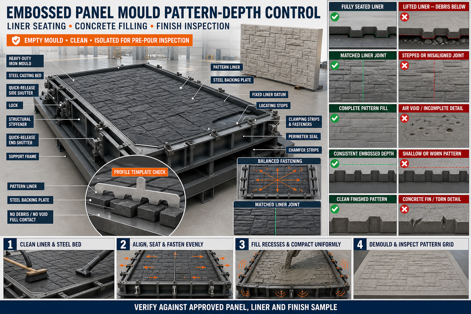
Embossed Panel Mould Pattern Depth Control: Liner Seating, Concrete Filling and Finish Inspection
Embossed Panel Mould Pattern Depth Control: Liner Seating, Concrete Filling and Finish Inspection
Embossed precast wall panels use decorative patterns to improve the appearance of boundary walls, industrial enclosures and infrastructure projects.
The visible design is formed by a pattern liner installed inside a heavy-duty iron panel mould. Every raised or recessed area on the liner creates the opposite feature on the concrete surface.
If the liner is not seated correctly or concrete does not fill its pattern cavities completely, the finished panel may contain shallow designs, incomplete details, air voids or mismatched pattern lines.
What Is an Embossed Panel Mould?
An embossed panel mould is an iron or steel mould fitted with a patterned forming liner.
A typical system may include:
• Heavy-duty steel casting bed • Side shutters • End shutters • Structural stiffeners • Pattern liner • Liner backing plate • Locating stops • Fasteners or clamps • Sealing strips • Quick locks • Chamfer strips • Reinforcement supports • Vibration arrangement
The mould should maintain the required panel dimensions and pattern geometry during production.
What Is Pattern Depth?
Pattern depth is the vertical difference between the high and low areas of the decorative concrete design.
It is controlled by:
• Liner geometry • Liner thickness • Recess depth • Liner seating • Backing-plate flatness • Concrete filling • Compaction • Release-agent application • Demoulding condition • Liner wear
Required pattern depth should follow the approved panel or liner drawing.
Why Pattern-Depth Consistency Is Important
Consistent depth helps provide:
• Uniform visual appearance • Clear design definition • Matching adjacent panels • Repeatable production • Reduced patching • Better surface finish • Controlled panel thickness • Easier quality inspection • Lower rejection • Longer liner service life
A decorative panel can be dimensionally correct while still having an unacceptable surface pattern.
What Is Liner Seating?
Liner seating describes how completely and evenly the pattern liner rests against its supporting steel bed or backing plate.
A properly seated liner should be:
• Flat against the approved support • Correctly oriented • Positioned against fixed datums • Securely fastened • Free from trapped debris • Properly sealed • Supported across its full area • Free from unintended movement
A small particle beneath the liner can create a local high spot.
Common Pattern-Depth Problems
Typical defects include:
• Shallow pattern • Excessively prominent pattern • Incomplete recess • Blurred detail • Local high or low area • Pattern mismatch • Visible liner joint • Surface voids • Honeycombing • Air pockets • Concrete fins • Torn or damaged details • Uneven colour or release marks
The defect should be traced back to its mould location.
Why an Embossed Pattern Becomes Shallow
A pattern may appear shallow because of:
• Worn liner • Concrete not entering deep recesses • Trapped air • Poor compaction • Excessive release-agent buildup • Damaged profile • Incorrect liner selection • Concrete paste buildup • Liner deformation • Unsuitable concrete workability
Do not assume that additional vibration will solve every shallow-pattern problem.
Why Pattern Depth Can Vary Across One Panel
Variation may result from:
• Uneven liner seating • Warped backing plate • Debris below the liner • Loose fasteners • Missing support • Concrete placed unevenly • Vibration concentrated in one area • Liner joints at different levels • Uneven release-agent application • Local liner wear
A systematic inspection should compare all panel zones.
Types of Pattern Liners
Pattern liners may create:
• Brick design • Stone texture • Wood-grain appearance • Geometric pattern • Tile-like design • Project-specific embossed profile • Custom architectural finish
The liner material and mounting arrangement should suit repeated concrete casting.
Role of the Heavy-Duty Iron Mould
The iron mould provides the structural support required to keep the liner flat and dimensionally stable.
It helps control:
• Panel length • Panel width • Panel thickness • Liner support • Shutter alignment • Joint sealing • Reinforcement position • Vibration transfer • Demoulding
A flexible or distorted backing surface can change the embossed finish.
Preparing the Mould for Liner Inspection
Before inspection:
• Remove the finished panel • Empty the mould • Open removable shutters • Isolate powered equipment • Mechanically secure movable components • Clean the mould bed • Remove concrete and slurry • Remove or expose the liner where required • Review the approved pattern drawing • Identify fixed reference datums • Prepare suitable inspection tools
Do not inspect beneath an unsupported liner or shutter.
Identifying the Correct Liner
Before installation, confirm:
• Pattern name or identification • Panel orientation • Top and bottom direction • Left and right edges • Pattern repeat • Matching adjacent liner sections • Approved panel size • Required fastener arrangement • Correct project reference
Incorrect orientation can create visible mismatch between installed panels.
Cleaning the Liner
Clean every pattern recess carefully.
Remove:
• Cement paste • Hardened concrete • Dust • Aggregate particles • Old release-agent deposits • Rust flakes from steel components • Damaged seal material • Foreign objects
Avoid cleaning tools that scratch, stretch or deform the pattern.
Cleaning the Backing Surface
The steel bed or backing plate should also be cleaned.
Check for:
• Weld spatter • Concrete particles • Rust scale • Loose fasteners • Raised sealant • Burrs • Dents • Local plate damage • Previous repair marks
The liner cannot sit flat on an uneven backing surface.
Inspecting Liner Condition
Inspect for:
• Surface wear • Torn features • Cracks • Cuts • Permanent deformation • Stretched sections • Damaged edges • Enlarged fixing holes • Loss of profile definition • Chemical deterioration • Local thickness variation
A damaged liner may produce the same defect on every panel.
Checking Liner Seating
A general seating inspection may include:
1. Clean the Liner and Bed
Remove all trapped material.
2. Position the Liner Against Fixed Datums
Confirm its orientation.
3. Apply Light Initial Fastening
Hold the liner without stretching it.
4. Check the Perimeter
Confirm the edges sit correctly.
5. Check the Centre
Look for lifted or unsupported areas.
6. Inspect Pattern-Joint Locations
Check matching and level.
7. Tighten Fasteners Progressively
Work from a controlled sequence.
8. Recheck Flatness
Confirm fastening has not distorted the liner.
9. Check Seal Continuity
Inspect the complete perimeter.
10. Complete a Final Visual Inspection
Confirm no tools or debris remain below the liner.
The installation method should follow the liner and mould manufacturer’s instructions.
Using a Straightedge for Seating Checks
A verified straightedge may help identify:
• Raised liner edge • Local bulge • Backing-plate distortion • Joint step • Uneven seating • Fastener-related depression
Use the method only where it will not damage the patterned surface.
Checking for Voids Beneath the Liner
Unsupported areas beneath the liner can flex under concrete pressure.
Possible inspection methods include:
• Approved tapping method • Visual edge inspection • Backing-support check • Fastener pattern review • Surface-level check • Manufacturer-specified method
Do not puncture or damage the liner during inspection.
Liner Fastening Systems
A liner may be secured using:
• Countersunk fasteners • Clamping strips • Edge clamps • Bolted backing plates • Mechanical retainers • Approved adhesive system • Combination mounting
The fastening arrangement should prevent movement without distorting the pattern.
Balanced Fastening Sequence
Uneven tightening may stretch or wrinkle a flexible liner.
A general sequence may include:
• Locate the liner at fixed datums • Engage central fasteners lightly • Work outward progressively • Alternate between opposite sides • Check pattern alignment • Inspect edges • Apply final fastening • Recheck seating and joint level
Do not fully tighten one corner before positioning the remaining liner.
Checking Liner Joints
Large panels may use multiple liner sections.
Inspect:
• Pattern continuity • Joint straightness • Joint height • Repeat spacing • Edge contact • Seal condition • Fastener position • Relationship with panel borders
An uneven liner joint may create a visible line or step in the concrete.
Pattern Matching Between Sections
Use fixed reference marks to align:
• Horizontal design lines • Vertical design lines • Brick or stone courses • Geometric repeats • Decorative borders • Custom motifs
Do not rely only on visual estimation across a long mould.
Sealing the Liner Perimeter
Slurry can enter beneath the liner through an open edge.
This can cause:
• Liner lifting • Concrete fins • Distorted pattern depth • Difficult liner removal • Hardened buildup • Surface marks • Faster liner wear
Use only the approved sealing arrangement.
Inspecting the Perimeter Seal
Check that the seal is:
• Continuous • Correctly seated • Undamaged • Evenly compressed • Free from debris • Compatible with the liner • Not excessively thick • Secure at corners
A thick seal can lift the liner perimeter.
Checking Pattern Depth With a Template
An approved profile template may help verify liner geometry.
Check:
• Peak position • Recess depth • Feature width • Transition shape • Repeated pattern consistency • Worn areas • Damaged corners
No generic pattern depth should be assumed.
Using a Reference Sample
An approved master panel or sample may assist with finish comparison.
The sample should be:
• Clearly identified • Protected from damage • Representative of the approved finish • Stored correctly • Available during inspection • Reviewed under suitable lighting
A damaged or unapproved sample should not be used as the acceptance reference.
Applying Mould Release Agent
Release agent must reach pattern recesses without excessive buildup.
Apply it:
• To a clean, dry liner where required • In a thin, uniform coat • Across raised and recessed areas • Without pooling • Without blocking fine details • Without contaminating reinforcement • According to liner compatibility instructions
Excess release agent can blur details and create surface stains.
Reinforcement Clearance
The reinforcement cage should not press against the liner.
Check:
• Panel cage dimensions • Required concrete cover • Spacer position • Stability • Clearance from pattern liner • Edge reinforcement • Lifting inserts where approved • Tie-wire position • Shutter closure
A displaced cage can press the liner against the backing surface or change panel cover.
Concrete Mix for Embossed Details
The approved concrete mix should provide suitable:
• Workability • Cohesion • Aggregate grading • Maximum aggregate size • Paste content • Resistance to segregation • Compatibility with vibration • Required strength
Do not add uncontrolled water to make the concrete enter the pattern.
Concrete Placement Over the Pattern Liner
Place concrete in a controlled sequence.
Good practices include:
• Distribute concrete evenly • Begin with adequate coverage over the pattern • Avoid dropping large loads onto one area • Prevent reinforcement movement • Fill corners carefully • Monitor liner edges • Avoid trapping air • Maintain a consistent layer
Direct impact can shift or damage a liner.
Filling Deep Pattern Recesses
Deep or narrow liner details may trap air.
To improve filling:
• Follow the approved mix design • Place concrete progressively • Use controlled vibration • Avoid aggregate bridging • Check concrete flow • Keep the mould level • Avoid excessive release agent • Monitor visible edges
The required method depends on the actual liner geometry.
Concrete Compaction
Compaction helps concrete reproduce the liner surface.
Depending on the system, it may use:
• Vibrator table • Shutter vibrator • Approved internal vibration • Controlled combined method
During compaction:
• Monitor liner movement • Check fasteners • Observe perimeter leakage • Prevent reinforcement movement • Avoid excessive vibration • Follow the approved sequence
More vibration can cause segregation or liner movement.
Under-Compaction Defects
Insufficient compaction can cause:
• Surface voids • Incomplete pattern • Honeycombing • Blurred features • Exposed aggregate • Poor corners • Uneven finish
The defect pattern can help identify the affected mould area.
Over-Compaction Defects
Excessive vibration may cause:
• Segregation • Paste concentration • Slurry leakage • Liner displacement • Pattern distortion • Colour variation • Reinforcement movement • Excessive surface laitance
Compaction should be controlled rather than prolonged automatically.
Monitoring During Casting
Observe safely for:
• Liner-edge leakage • Shutter movement • Fastener movement • Concrete flowing below the liner • Uneven filling • Reinforcement movement • Unusual vibration • Joint opening
Stop the process safely if significant liner movement occurs.
Curing the Panel
Curing should follow the approved concrete procedure.
Incorrect curing may contribute to:
• Surface cracking • Colour variation • Weak edges • Premature demoulding damage • Inconsistent appearance
Pattern inspection should consider the effect of lighting and moisture condition.
Preparing for Demoulding
Before opening the mould:
• Confirm adequate concrete strength • Support the panel • Isolate powered equipment • Mechanically secure shutters • Clean concrete around locks • Identify the approved opening sequence • Protect visible patterned surfaces • Prepare suitable lifting equipment • Keep personnel clear of pinch points
Do not lift a large panel only because the exposed surface appears dry.
Correct Demoulding Sequence
A general procedure may include:
1. Support the Concrete Panel
Prevent bending or uncontrolled movement.
2. Release Border Locks
Open them progressively.
3. Support Removable Shutters
Prevent impact on concrete edges.
4. Separate Border Shutters
Create clearance around the panel.
5. Release the Panel From the Liner
Use the approved lifting direction.
6. Avoid Sliding Across the Pattern
Protect the embossed surface.
7. Move the Panel to Inspection
Use approved lifting equipment.
8. Clean the Mould and Liner
Remove fresh slurry immediately.
Do not pry directly against the visible patterned face.
Why Patterns Tear or Break During Demoulding
Damage may occur because of:
• Concrete strength is insufficient • Release agent is missing • Liner contains an undercut • Concrete is bonded to buildup • Panel is lifted at an angle • Liner is damaged • Concrete fin locks the edge • Panel is unsupported • Incorrect demoulding direction
Repeated damage should be investigated at the liner.
Post-Demoulding Finish Inspection
Inspect the panel under suitable lighting.
Check:
• Overall pattern clarity • Pattern depth • Pattern continuity • Surface voids • Honeycombing • Liner-joint marks • Concrete fins • Edge condition • Colour consistency • Surface stains • Cracks • Panel dimensions
Record every defect according to mould location.
Creating a Pattern Inspection Grid
Divide the panel into repeatable inspection zones, such as:
• Top-left • Top-centre • Top-right • Middle-left • Centre • Middle-right • Bottom-left • Bottom-centre • Bottom-right
This helps identify a lifted liner or recurring compaction problem.
Comparing Pattern Depth
Use an approved:
• Profile gauge • Depth gauge • Template • Reference sample • Visual inspection standard • Digital scanning method where required
The measurement tool should not damage the concrete.
Distinguishing Liner Problems From Casting Problems
A liner problem may be suspected when:
• The same defect repeats in the same location • Pattern depth changes abruptly at a liner joint • A specific feature is always missing • Raised or lifted areas correspond to fasteners • Damage matches a torn liner
A casting problem may be suspected when:
• Defects move between panels • Voids appear randomly • Concrete consistency changes • Compaction was uneven • Reinforcement interfered • Release-agent coverage varied
Both problems can occur together.
Troubleshooting Common Pattern Defects
Problem: Pattern Is Shallow Across the Complete Panel
Possible causes:
• Incorrect liner selected • Liner profile is worn • Approved pattern depth was misunderstood • Release agent accumulated • Concrete did not reproduce fine details
Problem: Pattern Is Shallow in One Area
Possible causes:
• Liner is lifted • Debris remains below the liner • Backing plate is distorted • Concrete filling was incomplete • Vibration did not reach the area
Problem: Pattern Changes at a Liner Joint
Possible causes:
• Liner sections are at different levels • Pattern repeats are misaligned • Joint contains debris • Fasteners are uneven • Wrong liner section is installed
Problem: Surface Voids Appear in Deep Recesses
Possible causes:
• Trapped air • Aggregate bridging • Inadequate compaction • Unsuitable concrete workability • Excess release agent • Reinforcement congestion
Problem: Concrete Fin Appears Around the Pattern Edge
Possible causes:
• Liner perimeter gap • Damaged seal • Loose fastener • Lifted liner edge • Excessive vibration
Problem: Pattern Surface Is Torn
Possible causes:
• Premature demoulding • Concrete bonded to the liner • Damaged liner • Undercut feature • Incorrect lifting direction • Poor release-agent coverage
Problem: Visible Fastener Marks Appear
Possible causes:
• Fastener is raised • Liner is depressed around the fastener • Incorrect washer or retainer • Excessive tightening • Backing support is uneven
Correcting Liner-Seating Problems
A controlled correction may include:
• Removing the liner • Cleaning the backing surface • Repairing the steel bed • Replacing damaged fasteners • Correcting locating stops • Reinstalling from fixed datums • Tightening progressively • Rechecking pattern match • Replacing damaged seals • Conducting a trial casting
Do not add random packing beneath the liner.
Liner Maintenance Checklist
After every casting cycle:
• Clean all pattern recesses • Remove slurry from the perimeter • Inspect liner wear • Check tears and cuts • Inspect fixing holes • Check fasteners and clamps • Inspect seals • Check liner joints • Inspect the backing plate • Confirm locating stops • Apply approved storage protection • Store replacement liners correctly • Record recurring defects
Avoid folding or stacking liners in a way that causes permanent deformation.
Pre-Pour Pattern Checklist
Before concrete placement, confirm:
• Correct liner is selected • Pattern orientation is correct • Backing plate is clean • Liner is fully seated • No debris remains beneath it • Pattern joints match • Fasteners are progressively secured • Perimeter seal is continuous • Pattern profile is inspected • Release agent is uniformly applied • Reinforcement has adequate clearance • Shutters are aligned • Locks are secure • No tools remain inside the mould
Benefits of Pattern-Depth Control
Correct liner installation and casting provide:
• Consistent embossed depth • Clearer decorative details • Better matching between panels • Reduced surface voids • Fewer concrete fins • Lower repair work • Improved visual finish • Reduced rejection • Longer liner service life • More repeatable panel production
Conclusion
Pattern-depth control begins with the correct liner, a clean and flat steel backing surface and accurate seating against fixed mould datums.
The liner should be secured progressively, sealed around its perimeter and inspected for wear, lifting and joint mismatch. Concrete should then be placed and compacted in a controlled manner so that every pattern recess fills without segregation or liner movement.
A properly maintained heavy-duty iron embossed panel mould helps manufacturers produce decorative precast panels with consistent pattern depth, clean details and reliable finish quality.