
Precast Machinery Guide
Concrete Mixer Tilting Drum Alignment: Trunnion Wear, Drum Runout and Discharge Control
Trunnion wear, damaged pivots or excessive drum runout can cause vibration, uneven gear contact and poor discharge control. This guide explains safe alignment checks, support inspection and tilting-mechanism maintenance.
By Paras Steel Industries ·
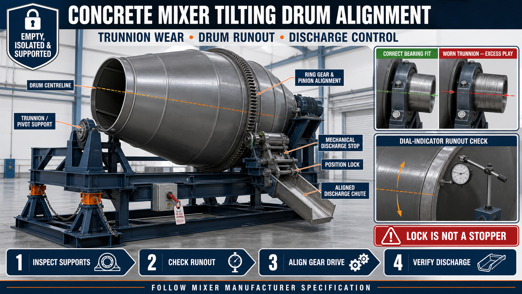
Concrete Mixer Tilting Drum Alignment: Trunnion Wear, Drum Runout and Discharge Control
Concrete Mixer Tilting Drum Alignment Guide
A tilting-drum concrete mixer rotates its steel drum during mixing and changes its position to discharge the finished concrete. For smooth operation, the drum axis, support arrangement, ring gear, drive pinion and tilting mechanism must remain correctly aligned.
Wear in trunnions, support rollers, pivot bearings or mounting brackets can allow the drum to move away from its designed centreline. The drum may then wobble, produce abnormal noise or discharge unevenly.
Excessive drum runout can also change ring-gear engagement during every revolution, placing additional stress on the pinion, bearings and drive system.
This guide explains concrete mixer tilting drum alignment, including support inspection, trunnion wear, drum runout and discharge-control checks.
Important Design Note
Not every tilting concrete mixer uses the same support arrangement.
Depending on the machine, the drum may use:
• Trunnion shafts • Pivot bearings • Support rollers • Drum rollers • Cradle bearings • Shaft-mounted support • Combination support systems
Inspect and maintain only the components included in the approved mixer design.
What Is a Tilting-Drum Concrete Mixer?
A tilting-drum mixer uses a rotating steel drum to combine cement, aggregates, water and admixtures. The drum or complete cradle can be tilted to control charging, mixing and discharge positions.
A typical mixer may include:
• Fabricated steel mixing drum • Mixing blades • Ring gear • Drive pinion • Electric or diesel drive • Gearbox • Trunnions or pivot shafts • Support bearings • Tilting cradle • Hand wheel or geared tilting mechanism • Mechanical stops • Discharge chute • Structural-steel chassis • Wheel or fixed-base arrangement • Protective guards
The exact configuration depends on the mixer model.
Why Drum Alignment Is Important
Correct alignment helps:
• Maintain smooth drum rotation • Keep ring-gear contact consistent • Reduce abnormal vibration • Protect support bearings • Reduce structural stress • Maintain controlled tilting • Improve discharge direction • Prevent drum contact with the chassis • Reduce seal and fastener wear • Support reliable production
Alignment should be checked whenever recurring noise or uneven movement appears.
Common Signs of Drum Misalignment
Operators may notice:
• Drum appears to wobble • Ring gear moves side to side • Pinion noise changes during each revolution • Support bearings become hot • Mixer vibrates more than normal • Drum rubs against the frame • Tilting requires excessive force • Drum does not remain at the selected position • Concrete discharges to one side • Mechanical stops contact unevenly • Mounting bolts repeatedly loosen • Chassis welds show cracking
Stop the mixer if movement becomes severe or unsafe.
Safety Before Alignment Inspection
The mixer contains rotating, electrical and stored-energy hazards.
Before inspection:
1. Stop the concrete mixer. 2. Disconnect and isolate the electrical supply. 3. Apply the plant’s lockout and tagout procedure. 4. Isolate diesel, hydraulic or pneumatic systems where fitted. 5. Wait until the drum stops completely. 6. Empty and clean the drum. 7. Secure the drum against rotation. 8. Mechanically support the tilting cradle. 9. Install approved maintenance pins or stops. 10. Keep personnel away from pinch points. 11. Wear suitable personal protective equipment.
Never work beneath a tilted drum supported only by the tilting gearbox, chain or hydraulic cylinder.
Mechanically Support the Drum
Before removing pivots, trunnions, rollers or bearings, support the drum and cradle at approved structural points.
The supports should:
• Match the machine load • Stand on firm, level ground • Contact reinforced steel areas • Prevent rotation and tilting • Remain stable during component removal • Avoid interference with measuring equipment • Keep personnel outside crush zones
Do not use loose wood, bricks or random scrap as maintenance supports.
Clean the Mixer Before Inspection
Concrete buildup can hide wear and change the drum’s balance.
Clean:
• Drum exterior • Ring gear • Drive pinion • Trunnion areas • Support rollers • Pivot bearings • Tilting cradle • Mechanical stops • Chassis • Discharge chute • Mounting bolts • Guards
Collect concrete slurry according to the plant’s environmental procedure.
Initial Visual Inspection
Before taking measurements, inspect:
• Drum position • Ring-gear condition • Pinion contact • Left and right supports • Trunnion brackets • Bearing housings • Support rollers • Tilting shaft • Hand wheel or gearbox • Mechanical stops • Cradle frame • Chassis welds • Mounting bolts • Previous repairs
Record abnormal wear at each location.
Establish a Fixed Datum
Use a stable machine reference for alignment measurements.
The datum may be:
• Chassis centreline • Machined bearing seat • Fixed cradle reference • Approved frame marks • Survey reference points
Do not measure every component only from the previous component because errors can accumulate.
Mark the Drum Centreline
Useful references may include:
• Drum rotational axis • Cradle centreline • Chassis centreline • Ring-gear plane • Pinion axis • Discharge centreline • Left and right support positions
These references help identify whether the problem is in the drum, supports or chassis.
Inspect the Structural-Steel Chassis
A distorted chassis can misalign the complete mixer.
Check:
• Main longitudinal members • Cross members • Bearing supports • Motor and gearbox base • Cradle brackets • Welded joints • Foundation contact • Anchor points • Wheel supports where fitted • Corrosion • Impact damage • Previous modifications
Correct structural problems before adjusting the drum.
Check Foundation Level
For a stationary mixer, inspect:
• Foundation level • Anchor-bolt condition • Base-frame contact • Packing plates • Concrete cracks • Settlement • Movement marks • Debris beneath the frame
For a mobile mixer, park it on a firm and level surface and secure the wheels before inspection.
What Are Trunnions?
A trunnion is a support shaft or pivot around which the drum or cradle rotates or tilts.
Depending on the mixer, trunnions may:
• Support drum rotation • Form the tilting pivot • Transfer drum load into bearings • Maintain the drum axis • Support the cradle • Carry the ring-gear side load
Confirm the component’s actual function from the mixer drawing.
Inspect Trunnion Shafts
Check trunnions for:
• Diameter wear • Grooves • Scoring • Pitting • Corrosion • Bending • Cracks • Uneven polishing • Damaged keyways • Thread damage • Loose retainers • Lubrication failure
A worn trunnion can allow the drum to drop or move sideways.
Check Trunnion Straightness
A bent trunnion may cause:
• Drum wobble • Bearing heating • Uneven ring-gear contact • Heavy tilting • Bracket stress • Seal damage • Repeated fastener loosening
Use an approved measuring setup. Do not straighten a critical shaft through uncontrolled heating or hammering.
Inspect Trunnion Bearings or Bushes
Check for:
• Excessive clearance • Rough rotation • Noise • Heat marks • Cracked housings • Loose fit • Corrosion • Grease contamination • Damaged seals • Metal particles • Misaligned mounting • Insufficient lubrication
Replace worn components according to the approved maintenance procedure.
Check Axial and Radial Movement
Unwanted trunnion movement may occur:
• Along the shaft axis • Vertically • Sideways • During direction changes • While the cradle is tilted
Use suitable measuring instruments and compare results with the manufacturer’s approved limits.
Inspect Trunnion Retainers
Check:
• Locknuts • Keeper plates • Split pins • Circlips • Retaining bolts • Washers • Spacers • End caps • Welded stops where designed
Missing retaining components can allow dangerous drum movement.
Support-Roller Inspection
Some mixers use rollers supporting a drum tyre or track.
Inspect rollers for:
• Uneven diameter wear • Flat spots • Cracks • Rough bearings • Axial movement • Corrosion • Concrete buildup • Misalignment • Loose shafts • Damaged retainers • Unequal contact marks
Rollers should remain compatible with the approved drum track.
Drum-Tyre or Track Inspection
Where fitted, inspect the drum tyre or running track for:
• Roundness • Wear • Cracks • Weld damage • Flat areas • Loose mounting • Concrete buildup • Uneven contact • Sideways movement • Corrosion
A damaged track can create apparent drum runout.
Check Roller Contact
All designed rollers should carry the intended load.
Unequal contact may indicate:
• Frame twist • Roller wear • Drum distortion • Incorrect adjustment • Foundation settlement • Bearing damage • Concrete buildup
Do not force one roller into contact without checking the complete alignment.
What Is Drum Runout?
Drum runout is the variation in the drum or ring gear’s position as it completes one revolution.
Runout may be:
• Radial—movement toward and away from the rotational axis • Axial—side-to-side movement along the axis • Local—distortion at one drum or gear section
Excessive runout may affect gear engagement and support loading.
Possible Causes of Drum Runout
Common causes include:
• Bent trunnion shaft • Worn bearings • Uneven support rollers • Distorted drum shell • Misaligned ring gear • Loose ring-gear mounting • Chassis twist • Drum-track damage • Concrete buildup • Previous impact • Uneven welding distortion
Identify the actual source before making adjustments.
Preparing for a Runout Check
Before measurement:
1. Empty and clean the drum. 2. Secure the mixer on a level base. 3. Inspect supports and bearings. 4. Establish a fixed measuring stand. 5. Clean the selected measurement surface. 6. Mark one drum reference position. 7. Rotate the drum only through the approved maintenance method. 8. Keep personnel clear. 9. Record measurements through a full revolution.
Do not use a loose or vibrating reference stand.
Dial-Indicator Runout Check
A dial indicator or approved measuring instrument may be used to check:
• Drum shell reference • Ring-gear face • Ring-gear outside diameter • Drum tyre • Shaft surface • Cradle position
The exact measuring points and acceptable values should come from the manufacturer.
Check More Than One Location
Measure:
• Near the front of the drum • Near the rear • At the ring gear • At the drum tyre where fitted • At both trunnions • At selected shell references
One point may not identify whether the problem is drum distortion or support misalignment.
Separate Ring-Gear Runout From Drum Runout
A ring gear can be misaligned even when the drum shell rotates correctly.
Check:
• Gear mounting bolts • Gear-to-drum connection • Segment joints where applicable • Gear face movement • Radial movement • Tooth contact • Concrete buildup • Damaged mounting pads
Do not adjust the drum supports only to compensate for a poorly mounted ring gear.
Inspect the Ring Gear and Pinion
Check:
• Gear teeth • Pinion teeth • Backlash • Tooth-contact pattern • Pinion-shaft alignment • Bearing play • Mounting bolts • Lubrication • Protective guard • Abnormal wear
Required backlash and contact should follow the approved gear specification.
Rhythmic Gear Noise
Noise that repeats once per drum revolution may indicate:
• Ring-gear runout • Damaged gear section • Loose gear segment • Drum wobble • Uneven tooth contact • Debris between teeth
Stop operation and inspect before continuing production.
Lubricating Trunnions and Bearings
Use the lubricant specified for the mixer components.
Good practices include:
• Clean grease fittings • Confirm passages are open • Apply a controlled amount • Rotate through the approved maintenance procedure • Inspect lubricant distribution • Wipe off excess grease • Protect seals • Record maintenance
Do not mix incompatible lubricants.
Insufficient Lubrication
Possible effects include:
• Bearing overheating • Shaft scoring • Heavy drum movement • Noise • Rapid wear • Corrosion • Bearing seizure
Excessive Lubrication
Excess lubricant can:
• Damage seals • Attract cement dust • Hide cracks • Spread onto floors • Contaminate nearby gears • Make inspection difficult
Use the recommended quantity.
Inspect the Tilting Cradle
The cradle supports the drum and allows controlled position changes.
Check:
• Cradle straightness • Cross members • Pivot brackets • Bearing seats • Welded joints • Stopper brackets • Gearbox connection • Hand-wheel shaft • Locking system • Corrosion • Impact damage
A twisted cradle can cause both drum runout and discharge misalignment.
Tilting-Pivot Inspection
Check the tilt pivot for:
• Pin wear • Bush wear • Bending • Cracked brackets • Loose retainers • Misalignment • Lubrication • Unwanted movement • Concrete buildup • Corrosion
The tilting pivot and rotating-drum support may be different systems.
Mechanical Stop Inspection
Tilting stops establish the approved drum positions.
Check:
• Charging stop • Mixing-position stop • Discharge stop • Contact plates • Locknuts • Welded brackets • Left-right contact • Wear • Deformation • Concrete buildup
The tilting gearbox should not remain loaded against a misaligned stop.
Drum Position Lock
Where fitted, inspect:
• Locking pin • Sector plate • Latch • Retaining clip • Hand-wheel lock • Ratchet mechanism • Pivot holes • Welded bracket • Full engagement
The lock should secure the drum after it reaches its approved position.
Do Not Use the Position Lock as a Stopper
The mechanical stop should establish the position before the lock engages.
Using the lock to absorb tilting impact can:
• Bend the pin • Enlarge holes • Crack brackets • Damage the sector plate • Create unsafe engagement
Approach all positions slowly.
Inspect the Tilting Gearbox or Hand Wheel
Check:
• Gear wear • Shaft play • Hand-wheel condition • Key and keyway • Bearing condition • Mounting bolts • Oil leakage • Protective guards • Locking mechanism • Abnormal noise
Do not operate a damaged tilting mechanism.
Tilting Balance Check
With the mixer empty and through the approved test procedure, observe:
• Initial movement • Movement through the approved range • Left-right balance • Sudden acceleration • Binding • Stopper contact • Lock engagement • Chassis movement
Stop if the drum moves unexpectedly.
Discharge-Control Function
Correct alignment should allow the drum to reach its intended discharge position without binding or overshooting.
Check:
• Drum discharge angle according to the drawing • Chute alignment • Concrete flow path • Stopper position • Position-lock engagement • Clearance from the chassis • Clearance from receiving equipment • Operator control
Do not modify the discharge position without approval.
Discharge Chute Alignment
Inspect the chute for:
• Centreline alignment • Straightness • Hinge condition • Mounting brackets • Concrete buildup • Wear • Cracks • Clearance • Locking arrangement • Relationship with the receiving trolley
A misaligned chute may make a correctly positioned drum appear to discharge poorly.
Common Discharge Problems
Concrete Discharges to One Side
Check drum position, chute alignment, internal buildup, blade condition and mixer level.
Concrete Remains Inside the Drum
Inspect mixing blades, drum buildup, discharge position, concrete workability and drum rotation.
Drum Overshoots the Discharge Position
Check tilting gearbox, mechanical stop, position lock and operating procedure.
Drum Does Not Reach the Stop
Inspect pivot binding, stop obstruction, gearbox condition and frame distortion.
Discharge Is Sudden and Uncontrolled
Check tilting balance, drive mechanism, locking system and operator controls.
Concrete Strikes the Chassis
Stop operation and inspect discharge position, chute arrangement and drum alignment.
Inspect Internal Mixing Blades
Worn or damaged blades can affect discharge even when drum alignment is correct.
Check:
• Blade profile • Blade mounting • Concrete buildup • Cracks • Bolts • Mixing direction • Discharge blade condition
Do not adjust drum alignment to compensate for worn blades.
Controlled Empty Rotation Test
After maintenance:
1. Confirm the drum is empty. 2. Remove tools. 3. Reinstall guards. 4. Clear personnel. 5. Remove lockout through the approved procedure. 6. Start the drum briefly. 7. Observe runout and vibration. 8. Listen for abnormal noise. 9. Stop the mixer. 10. Isolate it before reinspection. 11. Check fasteners and bearing temperature according to procedure. 12. Record the result.
Do not operate exposed ring gears or couplings.
Controlled Tilting Test
After the rotation test:
1. Stop drum rotation where required. 2. Clear the tilting area. 3. Move the drum slowly through each approved position. 4. Check pivot movement. 5. Observe stopper contact. 6. Engage the position lock. 7. Check discharge alignment. 8. Return to mixing position. 9. Stop if movement is jerky. 10. Record the test.
Begin with an empty mixer.
Production Trial
After successful empty tests, complete a controlled trial batch.
Monitor:
• Drum rotation • Vibration • Ring-gear noise • Bearing behaviour • Mixing uniformity • Tilting control • Discharge direction • Concrete remaining in the drum • Fastener movement
Stop if any abnormal condition returns.
Common Alignment Problems
Drum Wobbles During Rotation
Check trunnions, bearings, rollers, drum track, shell distortion and concrete buildup.
Ring-Gear Noise Changes Every Revolution
Inspect gear runout, mounting bolts, tooth damage and drum movement.
One Bearing Becomes Hot
Check lubrication, alignment, clearance, contamination and shaft condition.
Drum Rubs Against the Frame
Stop immediately and inspect support failure, runout, frame distortion and axial movement.
Tilting Is Heavy
Check pivot lubrication, bush wear, tilting gearbox, frame alignment and concrete buildup.
Mixer Pulls or Rocks on the Floor
Inspect foundation, anchors, wheel chocks, chassis and rotating imbalance.
Discharge Chute Does Not Align
Check mechanical stops, cradle position, chute mounting and frame distortion.
Mounting Bolts Repeatedly Loosen
Investigate excessive vibration, misalignment, worn supports and incorrect tightening procedure.
Preventive Maintenance Checklist
Daily or Pre-Use Checks
• Listen for abnormal noise • Observe drum movement • Inspect protective guards • Check visible fasteners • Inspect lubricant leakage • Check tilting lock • Remove concrete buildup • Verify discharge chute clearance
Scheduled Checks
• Inspect trunnion shafts • Check bearings and bushes • Inspect support rollers • Measure drum runout • Measure ring-gear runout • Check gear contact • Inspect cradle alignment • Verify mechanical stops • Inspect tilting gearbox • Check chassis welds • Inspect internal blades • Record trends and repairs
When Should the Mixer Be Stopped?
Stop using the tilting-drum mixer if you find:
• Cracked trunnions • Failed support bearings • Severely worn rollers • Drum contact with the chassis • Excessive runout • Loose ring gear • Broken gear teeth • Failed tilting lock • Cracked cradle brackets • Uncontrolled drum tilting • Repeated motor tripping • Damaged protective guards • Unstable chassis • Unsafe discharge movement
Production should resume only after repair and controlled testing.
Maintenance Records
Record:
• Mixer identification • Inspection date • Trunnion condition • Bearing condition • Runout measurements • Gear-contact condition • Lubrication • Stopper and lock condition • Repairs • Replaced parts • Test results • Recurring noise locations
Trend records can reveal gradual wear before failure.
Conclusion
Concrete mixer tilting drum alignment depends on a straight chassis, sound trunnions or support rollers, correctly positioned bearings and a stable tilting cradle.
Drum and ring-gear runout should be measured from a fixed reference. The discharge position should be established by approved mechanical stops and secured by the position lock without forcing the mechanism.
Paras Steel Industries supplies heavy-duty precast production machinery according to customer requirements and approved specifications. Planned trunnion inspection, runout measurement and discharge-control maintenance help support reliable mixing and controlled concrete handling.