
Precast Machinery Guide
Concrete Mixer Blade Wear: Mixing Uniformity, Inspection and Replacement Warning Signs
Worn, bent or heavily coated concrete mixer blades can create dead zones and inconsistent concrete batches. This guide explains safe blade inspection, wear comparison, mixing-uniformity checks and replacement warning signs.
By Paras Steel Industries ·
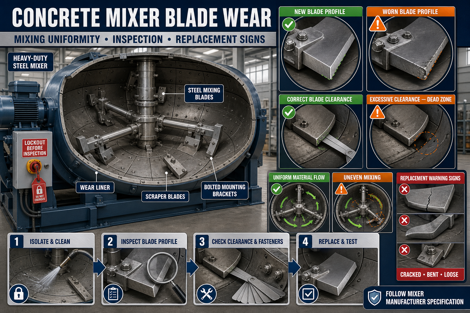
Concrete Mixer Blade Wear: Mixing Uniformity, Inspection and Replacement Warning Signs
Concrete Mixer Blade Wear Guide
Concrete mixer blades lift, turn and redistribute cement, aggregates, water and admixtures inside the mixing drum or pan. Their shape, position and clearance directly affect how the material moves during the mixing cycle.
As blades wear, their working edges can become rounded, shortened or uneven. Hardened concrete buildup may also change the blade profile and create dead zones where material does not circulate correctly.
These problems can result in inconsistent workability, uneven aggregate distribution and longer mixing cycles.
This guide explains concrete mixer blade wear, including safe inspection, mixing-uniformity diagnosis and replacement warning signs.
What Are Concrete Mixer Blades?
Mixer blades are heavy wear-resistant steel components installed inside a drum, pan or shaft mixer. They may also be called paddles, mixing arms or mixing shoes depending on the mixer design.
A typical mixing assembly may include:
• Steel mixing blades • Blade-support arms • Main mixing shaft • Blade mounting brackets • Bolts and locking devices • Drum or pan liner • Scraper blades • Discharge blades • Shaft seals • Bearings • Gearbox • Motor and drive system
The exact blade profile and arrangement depend on the concrete mixer model.
Purpose of Mixer Blades
Mixer blades are designed to move materials through a planned mixing path.
Their functions may include:
• Lifting aggregates • Folding materials together • Distributing cement • Moving water through the mix • Breaking local material concentrations • Reducing dead zones • Directing concrete toward discharge • Cleaning material from selected drum areas • Supporting uniform mixing
A damaged blade may interrupt this flow pattern.
Why Blade Wear Matters
Blade wear can affect:
• Concrete uniformity • Workability consistency • Mixing time • Aggregate distribution • Cement-paste distribution • Discharge efficiency • Motor loading • Energy consumption • Batch-to-batch consistency • Precast surface quality
Blade condition should be included in routine mixer maintenance.
Common Causes of Mixer Blade Wear
Normal Abrasive Wear
Sand and coarse aggregates repeatedly move across the blade surfaces, gradually removing material.
Hardened Concrete Buildup
Concrete deposits can change the blade profile and increase stress on mounting points.
Incorrect Blade Clearance
A blade positioned too close may strike the liner, while excessive clearance may leave unmixed material near the drum or pan surface.
Loose Mounting Bolts
A loose blade can move, vibrate and wear its mounting holes or support arm.
Foreign Material
Metal pieces, oversized stones or hardened concrete chunks can damage blade edges.
Incorrect Blade Material
Replacement blades that do not match the approved specification may wear quickly or fail unexpectedly.
Overloading
Excessive batch quantity can increase mechanical stress and reduce mixing efficiency.
Extended Mixing
Unnecessary mixing time increases blade contact with abrasive materials.
Corrosive Conditions
Standing water, chemicals and long storage periods may corrode steel components.
Safety Before Blade Inspection
Mixer blades can cause severe injury. Maintenance must never begin while the mixer is capable of starting.
Before inspection:
1. Stop the concrete mixer. 2. Disconnect and isolate the electrical supply. 3. Apply the plant’s lockout and tagout procedure. 4. Isolate hydraulic, pneumatic or mechanical energy. 5. Wait for all movement to stop. 6. Prevent drum or shaft rotation. 7. Secure the discharge mechanism. 8. Ventilate the mixer where required. 9. Follow the plant’s confined-space procedure when applicable. 10. Allow only trained personnel to enter or inspect the mixer.
Never depend only on the control-panel stop button.
Confined-Space and Access Safety
Some mixer interiors may be treated as confined or restricted-access spaces.
Before entry:
• Follow the site’s entry-permit procedure • Confirm safe atmospheric conditions where required • Provide an attendant • Use approved access equipment • Maintain communication • Keep emergency rescue arrangements available • Prevent material from entering the mixer • Control nearby equipment
Do not enter a mixer without the required site authorization.
Clean Before Inspecting
Hardened concrete can hide blade wear, cracks and loose fasteners.
Before inspection:
• Remove loose material • Clean blade surfaces • Clean mounting bolts • Remove buildup around support arms • Clean the liner • Inspect discharge areas • Keep cleaning water away from electrical components • Collect slurry according to plant procedures
Use cleaning methods that do not damage the blades or liner.
Avoid Unsafe Cleaning Methods
Do not use:
• Uncontrolled heavy hammering • Unapproved flame heating • Rotating the mixer during entry • Sharp tools near seals • Explosive or reactive cleaning chemicals • Unsupported access platforms • An excavator bucket inside the mixer
Follow the mixer manufacturer’s cleaning instructions.
Initial Blade Inspection
Inspect every blade systematically.
Look for:
• Rounded working edges • Reduced blade width • Uneven wear • Cracks • Bending • Chipped sections • Surface scoring • Corrosion • Impact damage • Hardened concrete buildup • Loose mounting bolts • Elongated bolt holes • Contact with the liner • Previous weld repairs
Mark each blade position so recurring wear can be tracked.
Create a Blade-Position Map
Blade wear may not be equal throughout the mixer.
Prepare a simple position map showing:
• Blade identification • Mixer location • Leading edge • Trailing edge • Distance from the liner • Wear condition • Fastener condition • Repair history • Replacement date
This helps identify high-wear zones.
Types of Blade Wear
Leading-Edge Wear
The edge facing material movement may become rounded or shortened.
Uneven Side Wear
One side may wear faster because of incorrect alignment or material-flow concentration.
Tip Wear
The outer blade tip may wear where movement is greatest.
Mounting-Hole Wear
Loose fasteners can enlarge the blade’s mounting holes.
Impact Damage
Foreign material can chip, crack or bend the blade.
Corrosion Wear
Moisture and chemicals can reduce the blade section during long shutdowns.
Blade-to-Liner Contact
Incorrect clearance may polish or damage both the blade and liner.
Inspect Blade Thickness and Profile
Compare the cleaned blade with:
• Approved new-blade profile • Manufacturer’s wear template • Recorded original dimensions • Replacement criteria • Matching blades in similar positions
Do not judge wear only by visual appearance.
Use a Wear Template
An approved template can help compare the working edge and blade profile.
The template should:
• Match the specific blade model • Be clearly identified • Remain undamaged • Be used at consistent locations • Be stored correctly • Follow the manufacturer’s inspection procedure
Do not use one generic template for unrelated blade designs.
Blade Clearance Inspection
Blade clearance is the gap between the working blade edge and the mixer drum, pan liner or adjacent component.
Correct clearance helps:
• Move material from the liner surface • Reduce dead zones • Prevent metal contact • Maintain the intended mixing pattern • Protect the blade and liner • Support effective discharge
Required clearance should follow the mixer manufacturer’s specification.
Signs of Excessive Blade Clearance
Excessive clearance may cause:
• Material buildup near the liner • Unmixed pockets • Longer mixing time • Reduced scraping action • Uneven cement distribution • Concrete remaining after discharge • Inconsistent workability
Worn blades, bent arms or an incorrect previous adjustment may be responsible.
Signs of Insufficient Clearance
Too little clearance may cause:
• Metal scraping noise • Polished contact marks • Blade overheating • Liner damage • Motor overloading • Bearing stress • Blade cracking • Sudden equipment stoppage
Stop the mixer if blade-to-liner contact is suspected.
How to Check Blade Clearance
A controlled inspection may include:
1. Isolate and secure the mixer. 2. Clean the blade and liner. 3. Identify approved measuring points. 4. Position the shaft through the maintenance procedure. 5. Measure the clearance. 6. Check the blade at multiple positions. 7. Compare matching blades. 8. Record the readings. 9. Compare them with the approved specification. 10. Correct the cause of any variation.
Use suitable measuring tools and never rotate the system while personnel are inside.
Inspect Blade Mounting Bolts
Blade fasteners operate under vibration and repeated loading.
Check:
• Bolt condition • Thread damage • Nut condition • Locking plates • Washers • Retainers • Contact surfaces • Elongated holes • Corrosion • Signs of movement
Fasteners should be tightened according to the manufacturer’s approved sequence and torque.
Do Not Use Assumed Torque Values
Incorrect tightening can cause:
• Loose blades • Broken bolts • Distorted mounting surfaces • Damaged threads • Cracked blades • Difficult future removal
Use the specified fasteners and tightening procedure.
Inspect Mixing Arms
A good blade cannot remain aligned if its support arm is damaged.
Check mixing arms for:
• Bending • Cracks • Weld damage • Corrosion • Loose shaft connection • Worn blade mounting face • Misalignment • Concrete buildup • Impact marks
Bent arms may create unequal clearance through the blade’s path.
Inspect the Mixer Liner
Blade wear and liner wear often occur together.
Inspect the liner for:
• Uneven thickness • Grooves • Cracks • Loose sections • Missing fasteners • Holes • Polished contact areas • Buildup • Corrosion • Deformation
Replacing worn blades without inspecting the liner may not correct clearance problems.
Inspect Scraper Blades
Some mixers use separate scraper blades near the wall or floor.
Check:
• Scraper profile • Wall clearance • Bottom clearance • Mounting bolts • Support-arm condition • Wear pattern • Contact marks • Material buildup
A worn scraper may leave concrete around the mixer perimeter.
Hardened Concrete Buildup
Concrete deposits can make a blade appear thicker while reducing its effective mixing shape.
Buildup may:
• Change blade geometry • Create imbalance • Hide cracks • Increase motor load • Reduce usable mixer volume • Break loose during production • Contaminate a new batch • Damage the liner or discharge gate
Clean buildup before evaluating actual blade wear.
Mixing Uniformity Problems
Blade wear may contribute to:
• Dry pockets • Uneven aggregate distribution • Inconsistent colour • Cement lumps • Variable workability • Excess material at one side • Longer mixing cycles • Incomplete discharge • Batch-to-batch variation
However, these symptoms may also have other causes.
Check the Complete Mixing Process
Before blaming the blades, inspect:
• Batching accuracy • Material charging sequence • Water distribution • Admixture dosing • Mixing duration • Batch quantity • Material moisture • Mixer speed • Discharge timing • Blade arrangement
Troubleshooting should cover the complete system.
Signs of Dead Zones
A dead zone is an area where material movement is weak.
Possible signs include:
• Repeated buildup in one location • Dry material after mixing • Concrete remaining after discharge • Uneven blade wear • Local material accumulation • Colour differences • Aggregate concentration
Inspect blade position, clearance and mixing-arm alignment near the affected area.
Blade Wear and Mixing Time
Operators may increase mixing time to compensate for worn blades. This may temporarily hide the problem but can increase energy use and component wear.
If mixing time gradually increases, inspect:
• Blade profiles • Blade clearance • Scraper condition • Liner wear • Batch size • Motor and gearbox • Material charging sequence
Do not permanently increase the cycle without identifying the cause.
Blade Wear and Motor Load
Worn blades do not always reduce motor load. Buildup, bent blades or contact with the liner may increase it.
Warning signs include:
• Motor overheating • Repeated tripping • Unusual current • Gearbox noise • Shaft vibration • Slow starting • Burning smell
Electrical testing must be carried out by qualified personnel.
Abnormal Noise Diagnosis
Scraping Sound
Check blade-to-liner contact, loose liner sections and bent mixing arms.
Knocking Sound
Inspect loose blades, damaged fasteners, foreign material and worn shaft connections.
Grinding Sound
Check bearings, gearbox, metal contact and trapped debris.
Rhythmic Impact
A bent blade or one damaged location may strike during each shaft revolution.
Stop the mixer and inspect before continuing production.
Blade Replacement Warning Signs
A blade may require replacement when it has:
• Reached the approved wear limit • Lost its required profile • Developed cracks • Become severely bent • Suffered major impact damage • Developed enlarged mounting holes • Lost secure mounting contact • Created unacceptable clearance • Contacted the liner • Caused recurring mixing defects • Been repaired beyond the approved limit
Final replacement criteria should follow the mixer manufacturer’s specification.
Replace Blades as a Balanced Set Where Required
Replacing only one blade may create imbalance or an inconsistent mixing pattern if the surrounding blades are also heavily worn.
The replacement approach depends on:
• Mixer design • Blade position • Wear distribution • Manufacturer recommendation • Weight balance • Matching profile • Mixing-flow arrangement
Use only approved matching blades.
Do Not Install Improvised Blades
Unapproved replacement blades may have the wrong:
• Material • Weight • Shape • Angle • Thickness • Mounting-hole position • Clearance • Wear resistance
This can affect mixing performance and equipment safety.
Blade Replacement Process
A controlled replacement may include:
1. Isolate and lock out the mixer. 2. Clean the mixing chamber. 3. Secure the shaft. 4. Mark blade positions and orientation. 5. Support the blade. 6. Remove the fasteners. 7. Inspect the support arm. 8. Clean the mounting face. 9. Install the approved replacement blade. 10. Fit approved fasteners and locking devices. 11. Set the required position and clearance. 12. Tighten according to the specified procedure. 13. Rotate the assembly manually through the approved method. 14. Confirm no contact. 15. Record the replacement.
Follow the manufacturer’s instructions for the specific mixer.
Blade Orientation
Some blades have a specific leading edge, angle or direction.
Before installation, confirm:
• Blade identification • Leading and trailing edges • Left- or right-hand position • Mounting face • Blade angle • Shaft rotation direction • Relationship with nearby blades
An incorrectly oriented blade can disrupt material flow.
Post-Replacement Clearance Check
After installing new blades:
• Check every replaced blade • Check nearby blades • Verify liner clearance • Inspect scraper clearance • Confirm fastener security • Rotate through the complete approved path • Look for interference • Record the result
Do not start the mixer until all tools and measuring equipment have been removed.
Controlled Empty Test
After maintenance:
1. Confirm guards are installed. 2. Clear personnel from the mixer. 3. Remove lockout through the approved procedure. 4. Start the mixer under controlled conditions. 5. Listen for abnormal noise. 6. Observe vibration. 7. Check motor operation. 8. Stop immediately if scraping or knocking occurs. 9. Isolate the mixer before reinspection.
Do not run an open or unguarded drive system.
Production Trial
After a successful empty test, complete a controlled trial batch.
Check:
• Material circulation • Mixing time • Concrete uniformity • Workability • Discharge efficiency • Material remaining in the mixer • Motor behaviour • Noise • Blade fasteners after shutdown
Quality testing should follow the plant’s approved concrete-control plan.
Common Blade Problems and Corrective Actions
One Blade Wears Faster
Check its position, angle, clearance, support-arm alignment and local material flow.
Concrete Builds Up Behind the Blade
Inspect blade orientation, dead zones, clearance and cleaning frequency.
Blade Bolts Repeatedly Loosen
Check mounting-face condition, bolt specification, locking arrangement, vibration and tightening procedure.
New Blade Contacts the Liner
Stop immediately and inspect blade position, arm bending, liner condition and clearance setting.
Mixer Takes Longer to Produce a Uniform Batch
Check blades, scrapers, liners, batch size, charging sequence and material moisture.
Concrete Does Not Discharge Completely
Inspect discharge blades, scraper condition, buildup, drum angle and discharge mechanism.
Cracked Blade
Remove the blade from service and investigate impact, material defects, loose mounting or unintended contact.
Preventive Maintenance Checklist
After Every Production Cycle
• Remove fresh concrete residue • Inspect visible buildup • Clean the discharge area • Listen for unusual noise • Check for loose components
Scheduled Checks
• Inspect every blade profile • Check blade clearance • Examine mounting bolts • Inspect mixing arms • Check scraper blades • Inspect the liner • Look for cracks and impact damage • Record blade wear • Compare mixing time • Review concrete uniformity • Replace worn components as required
When Should the Mixer Be Stopped?
Stop using the mixer if you find:
• Cracked blades • Loose blade fasteners • Blade-to-liner contact • Broken mixing arms • Severe concrete buildup • Abnormal knocking or scraping • Damaged liner sections • Repeated motor tripping • Excessive shaft vibration • Failed guards • Unsafe access conditions
Return the mixer to service only after repair and controlled testing.
Conclusion
Concrete mixer blade wear can affect material movement, mixing time, discharge efficiency and batch uniformity. Blade condition should therefore be evaluated through cleaning, profile inspection, clearance measurement and fastener checks.
Rounded edges, cracks, bent blades, excessive clearance, liner contact and recurring mixing defects are important replacement warning signs. The mixer liner, scraper blades, support arms and batching process should also be inspected before confirming the cause.
Paras Steel Industries supplies heavy-duty precast production machinery according to customer requirements and approved specifications. Planned mixer inspection and timely blade replacement can support consistent concrete production and reliable plant operation.