
Precast Machinery Guide
How to Clamp Precast Moulds on a Vibrator Table: Position, Resonance and Movement Control
Incorrect mould positioning or loose clamps can cause movement, noise and uneven concrete compaction on a vibrator table. This guide explains centre-of-gravity placement, clamp positioning, resonance diagnosis and safe test procedures.
By Paras Steel Industries ·
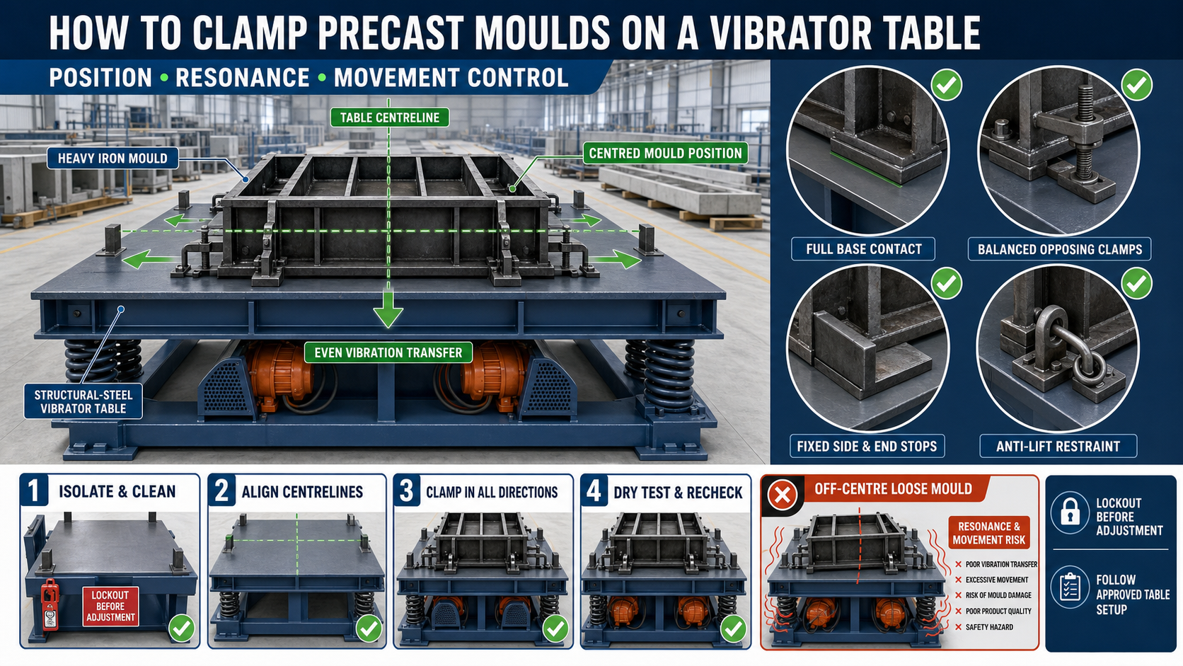
How to Clamp Precast Moulds on a Vibrator Table: Position, Resonance and Movement Control
How to Clamp Precast Moulds on a Vibrator Table
A vibrator table transfers controlled vibration through a steel platform into a precast mould. This vibration helps fresh concrete settle around reinforcement, fill corners and release trapped air.
For effective compaction, the mould must remain correctly positioned and securely restrained on the table. A loose or off-centre mould can slide, rotate, bounce or lift during operation.
Incorrect clamping may also create metal-to-metal impact, excessive noise, uneven vibration and structural damage.
This guide explains how to clamp precast moulds on a vibrator table, including mould positioning, clamp selection, resonance diagnosis and movement control.
Why Mould Clamping Is Important
Correct clamping helps maintain stable contact between the mould and vibrator-table platform.
It can support:
• Consistent vibration transfer • Controlled mould movement • Reduced metal impact • Uniform concrete compaction • Lower risk of mould displacement • Reduced damage to the table surface • Better reinforcement stability • Controlled slurry leakage • Improved operator safety • Repeatable production cycles
The clamping system should match the table and mould design.
What Happens When a Mould Is Not Clamped Properly?
An improperly secured mould may:
• Slide across the table • Rotate during vibration • Lift and strike the platform • Produce excessive noise • Move concrete to one side • Damage mould locks • Loosen embedded components • Change reinforcement cover • Wear the platform surface • Overload one group of springs • Damage clamps or stoppers • Fall from the operating area
Stop the table immediately if uncontrolled mould movement occurs.
Main Components of a Clamping System
A vibrator-table restraint system may include:
• Fixed side stops • Adjustable mechanical clamps • Toggle clamps • Wedge clamps • Bolted hold-down brackets • Locating pins • End stops • Crossbars • Approved spacer blocks • Guide rails • Anti-lift restraints • Dedicated mould feet
The correct arrangement depends on the mould size, shape, weight and table design.
Safety Before Positioning a Mould
A precast mould may be heavy even before concrete is added.
Before positioning:
1. Stop and electrically isolate the vibrator table. 2. Apply the plant’s lockout and tagout procedure. 3. Wait until all movement has stopped. 4. Clean the platform. 5. Inspect the lifting equipment. 6. Confirm the mould’s empty weight and lifting points. 7. Clear personnel from the movement area. 8. Use approved handling equipment. 9. Keep hands away from pinch points. 10. Lower the mould slowly onto the table.
Never position or adjust a mould while the vibrator table is running.
Inspect the Vibrator Table First
Before loading a mould, inspect:
• Table platform • Structural frame • Welded joints • Springs • Spring seats • Motor mounting bolts • Anchor points • Electrical cables • Control panel • Emergency stop • Clamps and stoppers • Previous impact marks
Do not operate the table if structural or electrical defects are present.
Clean the Table Platform
Hardened slurry, aggregate particles and debris can prevent the mould base from sitting flat.
Clean:
• Platform surface • Clamp channels • Locating-pin holes • Side stops • Mould contact areas • Drainage points • Platform edges
A mould resting on concrete deposits may rock during vibration.
Inspect the Mould Base
The mould base should make stable contact with the vibrator-table surface.
Check:
• Base-frame straightness • Mould feet • Contact plates • Welded supports • Loose components • Concrete buildup • Corrosion • Protruding bolts • Previous impact damage • Suitable clamping points
A distorted mould base can create uneven vibration transfer.
Confirm Table Compatibility
Before loading, verify:
• Mould fits within the approved table area • Total operating load is permitted • Table structure is suitable • Clamp locations match the mould base • Springs and motors suit the intended operation • Mould does not interfere with moving components • Concrete placement can be completed safely • Electrical cables remain protected
Do not place a mould on a table only because it physically fits.
Find the Mould Centre of Gravity
The mould should be positioned so that its operating centre of gravity remains close to the table’s approved loading centre.
The operating load includes:
• Iron mould • Fresh concrete • Reinforcement cage • Embedded components • Temporary casting accessories • Concrete-placement equipment resting on the mould, if any
A mould that is centrally positioned while empty may become unbalanced after concrete placement.
Mark the Table Centreline
Useful reference markings may include:
• Longitudinal centreline • Transverse centreline • Approved loading boundary • Fixed datum • Clamp zones • Restricted areas • Mould reference points
Keep these markings visible and use them for repeatable mould placement.
Position the Mould From a Fixed Datum
A suitable positioning sequence is:
1. Identify the table datum. 2. Mark the mould centreline. 3. Lower the mould onto the platform. 4. Align both centrelines. 5. Confirm the approved orientation. 6. Check clearance on every side. 7. Verify contact at all mould feet. 8. Install the restraints loosely. 9. Recheck the mould position. 10. Complete the clamping sequence.
Do not align the mould only by looking at one edge.
Why Off-Centre Placement Causes Problems
An off-centre mould can create unequal loading on the table springs and structure.
Possible results include:
• Stronger vibration on one side • Unequal spring compression • Sideways platform movement • Mould travel • Poor concrete compaction • Excessive motor loading • Structural vibration • Unusual noise • Accelerated component wear
Correct positioning should be confirmed before adjusting vibration settings.
Choose Approved Clamping Points
Clamps should act on structural parts of the mould base.
Suitable locations may include:
• Base-frame members • Dedicated clamping brackets • Reinforced feet • Approved cross members • Designed hold-down points
Avoid clamping against:
• Thin casting plates • Hinges • Locking handles • Hydraulic cylinders • Sealing flanges • Decorative liners • Electrical components • Unsupported shutter edges
Clamping a weak area can deform the iron mould.
Clamp Direction
A clamping arrangement may need to control movement in several directions:
• Longitudinal movement • Lateral movement • Rotation • Vertical lifting or bouncing
Side stops alone may not prevent the mould from lifting. Hold-down clamps alone may not prevent sideways travel.
The restraint system should address the expected movement according to the approved table design.
Use at Least Two Independent References
The mould position should normally be controlled by:
• A fixed location reference • A second stop or clamp preventing rotation
The exact number and position of clamps must follow the engineering design. Do not apply one general clamp quantity to every mould.
Balanced Clamp Placement
Clamps should be distributed around the mould rather than concentrated at one corner.
Balanced placement helps:
• Maintain full base contact • Prevent mould rotation • Reduce local frame distortion • Control movement in opposing directions • Distribute restraint forces • Maintain table balance
Opposing clamps should be engaged gradually.
Correct Clamping Sequence
A practical sequence includes:
1. Place the mould against the approved fixed stops. 2. Install all clamps loosely. 3. Confirm the mould centreline. 4. Check full base contact. 5. Engage opposing side restraints. 6. Engage longitudinal restraints. 7. Apply anti-lift restraints where designed. 8. Tighten clamps gradually. 9. Recheck mould position. 10. Confirm all retaining parts are secure.
The exact sequence should follow the table manufacturer’s instructions.
Avoid Over-Tightening
Excessive clamping force can:
• Distort the mould base • Bend clamp brackets • Pull the platform out of level • Damage threads • Create local stress • Make removal difficult • Affect mould dimensions
Fasteners should be tightened according to the approved procedure and specified torque where applicable.
Avoid Under-Tightening
Insufficient clamp engagement may allow:
• Mould sliding • Clamp movement • Metal impact • Rotation • Lifting • Loosening during vibration • Concrete spillage
Inspect clamp engagement before every operating cycle.
Inspect Clamps Before Use
Check every clamp for:
• Cracks • Bending • Thread wear • Damaged nuts • Worn contact pads • Loose pins • Missing retainers • Corrosion • Weld damage • Concrete contamination • Unapproved repairs
Damaged clamps should be replaced before operation.
Use Proper Contact Pads
Where designed, suitable contact pads help distribute clamping force and protect the mould base.
Contact pads should:
• Fit the clamp correctly • Sit on a reinforced mould area • Remain securely retained • Resist vibration • Avoid contaminating concrete • Be checked for wear
Do not use loose random packing that may escape during vibration.
What Is Resonance?
Resonance occurs when an operating vibration frequency interacts with the natural vibration behaviour of the table, mould or combined loaded system.
It may cause vibration amplitude to increase unexpectedly.
The combined system includes:
• Vibrator table • Springs • Motors • Mould • Fresh concrete • Reinforcement • Clamping arrangement • Foundation
Changing the mould or load can change the system’s vibration behaviour.
Signs of Possible Resonance
Warning signs may include:
• Sudden increase in movement • Mould bouncing • Excessive platform displacement • Loud rhythmic impact • Rapid clamp loosening • Strong vibration in nearby structures • Unusual spring movement • Vibration increasing at a particular operating setting • Concrete moving excessively • Electrical motor loading changes
Stop the table if vibration becomes uncontrolled.
Resonance Is Not Always a Clamp Problem
Loose clamps may produce symptoms similar to resonance. Before changing machine settings, inspect:
• Mould contact with the platform • Clamp tightness • Mould position • Spring condition • Motor mounting • Table-frame cracks • Foundation contact • Loose mould shutters • Concrete distribution • Nearby structural contact
Diagnose the complete system.
Vibration-Motor Settings
Any adjustment to motor speed, eccentric weights or rotation direction should be carried out according to the machine manufacturer’s instructions.
Do not change settings only to stop visible movement without identifying the underlying cause.
Incorrect adjustment can:
• Overload springs • Damage the table frame • Increase mould movement • Cause concrete segregation • Overheat motors • Loosen fasteners • Reduce compaction quality
Electrical adjustments must be performed by qualified personnel.
Check Spring Compression
Before operation, compare the table springs.
Unequal compression may indicate:
• Off-centre load • Damaged spring • Distorted table frame • Mismatched spring • Incorrect mould position • Concrete buildup • Structural settlement
Springs should match the approved table specification.
Check Mould Contact During a Dry Test
Where the approved operating procedure permits, conduct a short controlled test with the empty mould.
Observe from a safe position:
• Mould movement • Clamp movement • Metal impact • Table displacement • Spring behaviour • Noise • Motor operation • Contact between mould and platform
Stop immediately if the mould shifts or lifts.
Do Not Stand Beside a Moving Mould
During testing:
• Keep personnel outside the movement zone • Use barriers where required • Keep the emergency stop accessible • Observe from a safe position • Do not touch clamps • Do not tighten components while operating • Stop and isolate the system before adjustment
Never attempt to restrain a moving mould manually.
Loaded Test and Concrete Placement
After a successful empty test, prepare the mould for concrete casting.
Before vibration:
• Confirm reinforcement position • Check mould locks • Verify insert locations • Recheck clamps • Confirm load distribution • Inspect concrete placement • Clear tools from the platform • Keep hoses and cables away from moving components
Concrete should be distributed evenly before and during vibration.
Control Concrete Distribution
Uneven concrete placement changes the table load and centre of gravity.
During casting:
• Place concrete in a planned sequence • Avoid loading one end completely first • Distribute concrete progressively • Monitor reinforcement • Observe mould movement • Stop if the table becomes unbalanced • Avoid overfilling the mould • Follow the approved vibration procedure
Balanced concrete placement supports more uniform compaction.
Movement-Control Stops
Fixed or adjustable stops can prevent the mould from travelling across the table.
Inspect stops for:
• Correct position • Structural strength • Contact with the mould • Weld condition • Fastener security • Wear • Clearance • Interference during loading
Stops should contact structural parts of the mould base.
Anti-Lift Restraints
Where bouncing is possible, the approved setup may include anti-lift clamps or hold-down bars.
Inspect:
• Clamp position • Vertical clearance • Contact pads • Locking pins • Retaining parts • Structural attachment • Mould clearance during setup
Do not add improvised overhead restraints.
Mould-to-Table Contact Problems
Common contact problems include:
• Rocking mould base • Concrete debris beneath the mould • Bent mould feet • Unequal support pads • Damaged table surface • Local gaps • Protruding welds • Distorted base frame
Correct the contact problem before increasing clamping force.
Common Clamping Problems
Mould Slides Sideways
Check lateral stops, clamp engagement, mould position, platform cleanliness and vibration balance.
Mould Rotates
Inspect opposing stops, longitudinal restraints and off-centre concrete placement.
Mould Bounces
Check anti-lift restraints, base contact, resonance, spring condition and vibration settings.
Clamps Repeatedly Loosen
Inspect threads, locking devices, clamp wear, excessive vibration and correct tightening procedure.
Mould Produces Loud Impact Noise
Check for base gaps, loose shutters, worn clamps, damaged stops and uncontrolled resonance.
One Side Compacts Faster
Inspect mould position, concrete distribution, spring compression, motor synchronization and table structure.
Clamp Bends the Mould Base
The clamp may be positioned on an unsupported section or tightened excessively.
Table Moves on the Foundation
Stop operation and inspect anchors, foundation condition, spring system, load position and vibration settings.
Slurry Leakage During Vibration
Check mould locks, flange seals, clamping distortion, concrete workability and excessive vibration.
Post-Operation Inspection
After completing the vibration cycle:
1. Stop the machine. 2. Wait for all movement to stop. 3. Isolate the electrical supply. 4. Inspect clamp positions. 5. Check for loosened fasteners. 6. Observe mould displacement. 7. Inspect table and mould contact points. 8. Clean slurry before it hardens. 9. Record abnormal noise or movement. 10. Repair defects before the next cycle.
Repeated movement marks can help identify inadequate restraint locations.
Preventive Maintenance Checklist
Before Every Use
• Clean the platform • Inspect the mould base • Check centrelines and datum marks • Inspect clamps and stops • Confirm all retainers • Check spring condition • Inspect motor mounting • Verify mould locks • Confirm safe concrete distribution
Scheduled Checks
• Inspect table flatness • Check structural welds • Service clamps and threads • Inspect contact pads • Verify stop positions • Examine springs and spring seats • Check motor synchronization • Inspect electrical cables • Check foundation anchors • Record mould-specific setups
When Should Operation Be Stopped?
Stop using the vibrator table if you observe:
• Uncontrolled mould movement • Mould lifting or bouncing • Broken clamps • Failed stops • Damaged springs • Cracked structural members • Loose motor mounting • Severe platform movement • Repeated electrical tripping • Exposed electrical cables • Abnormal bearing noise • Mould displacement during a test
Operation should resume only after the fault is corrected and a controlled test is completed.
Create a Setup Record for Each Mould
If different moulds are used on one vibrator table, prepare a documented setup for each one.
The record may include:
• Mould identification • Approved table orientation • Fixed-datum position • Clamp locations • Stop positions • Loading sequence • Vibration procedure • Inspection points • Known restrictions • Previous movement observations
A repeatable setup reduces dependence on visual judgement.
Conclusion
Correctly clamping a precast mould on a vibrator table requires more than tightening a few brackets. The mould must be compatible with the table, positioned around the approved loading centre and restrained against sideways movement, rotation and lifting.
Possible resonance should be investigated by checking the complete system, including mould contact, clamps, springs, motors, load distribution and foundation condition. Machine settings should only be adjusted according to the approved equipment procedure.
Paras Steel Industries manufactures heavy-duty iron precast moulds and structural-steel vibrator tables according to customer requirements and approved drawings. Correct positioning, balanced clamping and controlled testing help support consistent compaction and safer precast production.