
Precast Mould Guide
Cable Trench Mould for Electrical Projects: Sizes, Cover Slabs and Joint Details
A precast cable trench system provides a protected and accessible route for electrical, communication and control cables. This guide explains cable trench mould sizes, cover-slab options, joint details and heavy-duty iron and steel mould requirements.
By Paras Steel Industries ·
Cable Trench Mould for Electrical Projects: Sizes, Cover Slabs and Joint Details
Cable Trench Mould for Electrical Projects: Sizes, Cover Slabs and Joint Details
Precast concrete cable trenches provide a protected route for electrical power, communication, instrumentation and control cables. They are commonly installed in substations, power plants, industrial facilities, solar projects, railway systems and infrastructure developments.
A complete cable trench system generally includes precast trench sections, removable cover slabs and properly designed joints. The mould must reproduce the required dimensions, wall thickness, bearing ledges and connection details accurately.
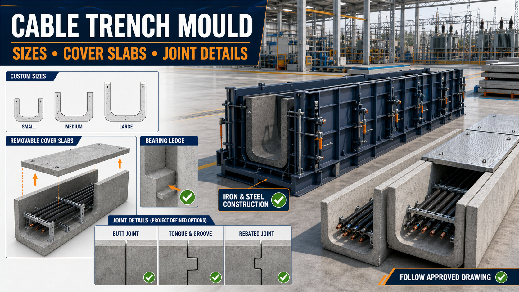
Paras Steel Industries manufactures precast moulds using iron and heavy-duty steel components. Cable trench dimensions, cover-slab arrangements, joint details and production capacity can be customized according to the customer’s approved product drawings.
What Is a Cable Trench Mould?
A cable trench mould is an iron or steel mould used to manufacture precast concrete channels for carrying electrical and communication cables.
The trench section may have a U-shaped or rectangular open-top profile. Cover slabs are installed over the opening after cable placement to protect the services while allowing future inspection and maintenance.
A cable trench mould may include:
• Heavy-duty iron or steel base frame • External side shutters • Inner-core shutters • Removable end plates • Cover-slab bearing-ledge formers • Joint-forming arrangements • Alignment rods and locks • Structural angles and channels • Mechanical or hydraulic opening systems • Vibration-compatible supports
The mould design depends on the trench dimensions, product length, wall thickness, joint type and required production capacity.
Where Are Precast Cable Trenches Used?
Precast cable trenches may be used in:
• Electrical substations • Power-generation plants • Solar and wind-energy projects • Industrial factories • Railway and metro projects • Data and communication facilities • Oil and gas installations • Water-treatment plants • Airports and ports • Large commercial developments • Highway and tunnel infrastructure
The trench design should consider cable quantity, cable-bending requirements, maintenance access, drainage and expected external loading.
Cable Trench Sizes
Cable trench dimensions are normally selected according to the number and type of cables, project layout and available installation space.
Important dimensions include:
• Internal clear width • Internal clear depth • Overall external width • Overall height • Wall thickness • Base-slab thickness • Product length • Cover-slab bearing width • Joint depth and clearance • Cable-support position
There is no single standard size suitable for every electrical project. A small communication-cable trench may require a different section from a high-voltage power-cable trench.
The mould should therefore be manufactured from an approved project drawing rather than assumed dimensions.
Internal Width
Internal width should provide sufficient space for cable placement, separation and future maintenance. It may also need to accommodate cable trays or support brackets.
Internal Depth
Depth depends on cable quantity, bending radius, support arrangement and required protection.
Wall and Base Thickness
Wall and base thickness are determined by the structural design, reinforcement arrangement, soil pressure and installation conditions.
Product Length
Longer sections may reduce the number of field joints but increase mould weight, product weight and handling requirements.
Fixed-Size vs Adjustable Cable Trench Mould
Fixed-Size Mould
A fixed-size mould is designed for one approved trench section.
Possible benefits include:
• Simple operation • Consistent dimensions • Faster setup • Suitability for repetitive production
Adjustable Mould
An adjustable mould may contain movable shutters or partitions for producing compatible sizes.
Possible benefits include:
• Greater production flexibility • Reduced need for separate moulds • Better response to customized orders • Improved use of factory space
Every adjustment position must be measured and aligned before casting.
Cover Slabs for Cable Trenches
Cover slabs protect cables from debris, weather, accidental contact and external loads. They also allow the cable route to be opened for inspection or maintenance.
Cover slabs may be designed as:
• Individual removable concrete slabs • Reinforced heavy-duty slabs • Lightweight hand-removable units • Interlocking cover slabs • Slabs with lifting holes • Slabs with recessed lifting hooks • Ventilated covers where approved • Load-rated covers for vehicle-access areas
The cover type must match the project’s structural and operational requirements.
Cover-Slab Bearing Ledge
Many cable trenches include an internal ledge or rebate near the top of the walls. The cover slabs sit on this bearing surface.
The mould must form the ledge accurately because an uneven or incorrectly positioned ledge can cause:
• Rocking cover slabs • Uneven finished levels • Insufficient bearing • Edge damage • Installation difficulty • Water and debris entry
The bearing width, depth and level should match the approved drawing.
Separate Cover-Slab Mould
Cover slabs are generally produced in a separate iron or steel mould.
A cover-slab mould may include:
• Steel casting bed • Adjustable side shutters • Removable end partitions • Lifting-hole formers • Recess formers • Interlocking-edge formers • Structural stiffeners • Mechanical locking points
Multi-cavity cover-slab moulds may be used when high daily production is required.
Cable Trench Joint Types
Joints connect adjoining trench sections and help maintain alignment during installation.
Common joint arrangements may include:
Butt Joint
Two flat end faces are positioned together. This is simple but requires accurate installation and alignment.
Tongue-and-Groove Joint
One section contains a projecting tongue and the adjacent section contains a matching groove. This can improve alignment between sections.
Rebated Joint
Matching steps or rebates are formed at the ends. The arrangement may help with positioning and joint sealing.
Socket or Male-Female Joint
One end is shaped to fit into the adjoining section. This provides positive alignment when designed correctly.
The correct joint must be selected by the project designer according to structural, installation and sealing requirements.
Importance of End-Plate Accuracy
The mould end plates create the cable trench joint geometry. Incorrect end plates can cause installation gaps, level differences or difficulty connecting adjacent units.
Before casting, check:
• End-plate position • Joint depth • Tongue or groove dimensions • End-face squareness • Product length • Locking arrangements • Slurry-sealing surfaces
End plates must be securely locked so that they do not move during concrete pouring and vibration.
Joint Sealing and Drainage
Cable trench joints may require approved sealing materials to reduce the entry of water, soil and debris.
Possible sealing arrangements include:
• Cementitious joint treatment • Approved sealant • Compressible sealing strip • Rubber gasket in specially designed systems • External waterproofing treatment
The mould creates the joint geometry but does not by itself make the complete system waterproof. Joint sealing should follow the approved project specification.
Drainage should also be considered. Water entering a cable trench must be directed toward approved drainage points, sumps or outlets.
Reinforcement Placement
The reinforcement cage should follow the approved structural drawing.
Important checks include:
• Reinforcement-bar diameter • Bar spacing • Concrete cover • Corner reinforcement • Reinforcement around lifting points • Reinforcement near bearing ledges • Joint-end reinforcement • Position of embedded components
Suitable spacers should keep the reinforcement centred inside the mould.
Cable Supports and Embedded Components
Some cable trenches require internal supports, inserts or fixing points for cable trays.
These may include:
• Embedded channels • Threaded inserts • Support brackets • Earthing connections • Divider supports • Cable-rack fixing points
Every insert should be positioned using an accurate mould fixture. Loose inserts can move during vibration.
Production Process
A typical cable trench production cycle includes:
1. Clean the iron or steel mould. 2. Inspect the shutters, joints and locking points. 3. Apply a suitable mould-release agent. 4. Install end plates and joint formers. 5. Position the reinforcement cage. 6. Fix approved inserts and lifting components. 7. Close and align the mould shutters. 8. Check internal dimensions and squareness. 9. Pour concrete uniformly. 10. Compact the concrete using the approved vibration method. 11. Finish the exposed surface. 12. Cure the product correctly. 13. Demould after sufficient strength is achieved. 14. Inspect dimensions, joints and surface quality. 15. Store the section on suitable supports.
Cover slabs should be manufactured and cured according to their approved design.
Quality-Control Checks
Inspect every production batch for:
• Internal width and depth • Overall dimensions • Wall and base thickness • Product length • Straightness and squareness • Cover-slab ledge position • Joint geometry • End-face alignment • Insert position • Concrete cover • Honeycombing and cracks • Damaged corners • Concrete strength • Cover-slab fit
A trial assembly of adjoining trench sections can help verify joint compatibility.
Common Production Problems
Slurry Leakage
Loose shutters and damaged joints can allow cement slurry to escape, causing poor edges and dimensional variation.
Unequal Wall Thickness
This may result from inner-core misalignment, loose locking points or movement during vibration.
Cover Slabs Do Not Fit
Possible causes include incorrect bearing-ledge dimensions, cover-slab mould errors or insufficient installation clearance.
Trench Sections Do Not Join Properly
Incorrect end-plate positioning or damaged joint formers can affect the connection.
Difficult Demoulding
Concrete residue, inadequate release agent, insufficient clearance or premature demoulding may cause sticking and edge damage.
Mould Maintenance
After every casting cycle:
• Remove concrete residue. • Clean the inner core and shutters. • Inspect joints and end plates. • Check locking pins, bolts and clamps. • Clean the cover-slab ledge formers. • Inspect tongue-and-groove formers. • Check steel plates for bending. • Examine welds, angles and channels. • Lubricate approved moving parts. • Repair slurry-leakage points. • Verify mould dimensions periodically.
Proper maintenance helps preserve joint accuracy and product consistency.
Factors to Check Before Buying
Before ordering a cable trench mould, share:
• Approved trench drawing • Internal and external dimensions • Product length • Wall and base thickness • Cover-slab details • Bearing-ledge dimensions • Joint type • Reinforcement drawing • Required number of cavities • Expected daily production • Manual or hydraulic operating preference • Vibration method • Lifting and handling arrangement • Required dimensional tolerance • Embedded-component details
If cover slabs are also required, provide their complete dimensions, reinforcement, load requirements and lifting arrangement.
Conclusion
A cable trench mould must accurately produce the required trench dimensions, cover-slab bearing ledges and end-joint details.
Correct mould alignment, reinforcement placement, joint-former positioning and regular maintenance are essential for consistent production and smooth site installation.
Paras Steel Industries manufactures heavy-duty iron and steel precast moulds according to customer drawings and production requirements. Buyers should provide complete cable trench and cover-slab specifications before mould design and manufacturing begin.