
Precast Mould Guide
Cable Trench Mould Shutter Vibrator Mounting: Pad Location, Bolt Security and Compaction Control
Incorrect shutter-vibrator mounting can create dead zones, loose fasteners, slurry leakage or excessive vibration in a cable trench mould. This guide explains mounting-pad position, bolt inspection and controlled compaction.
By Paras Steel Industries ·
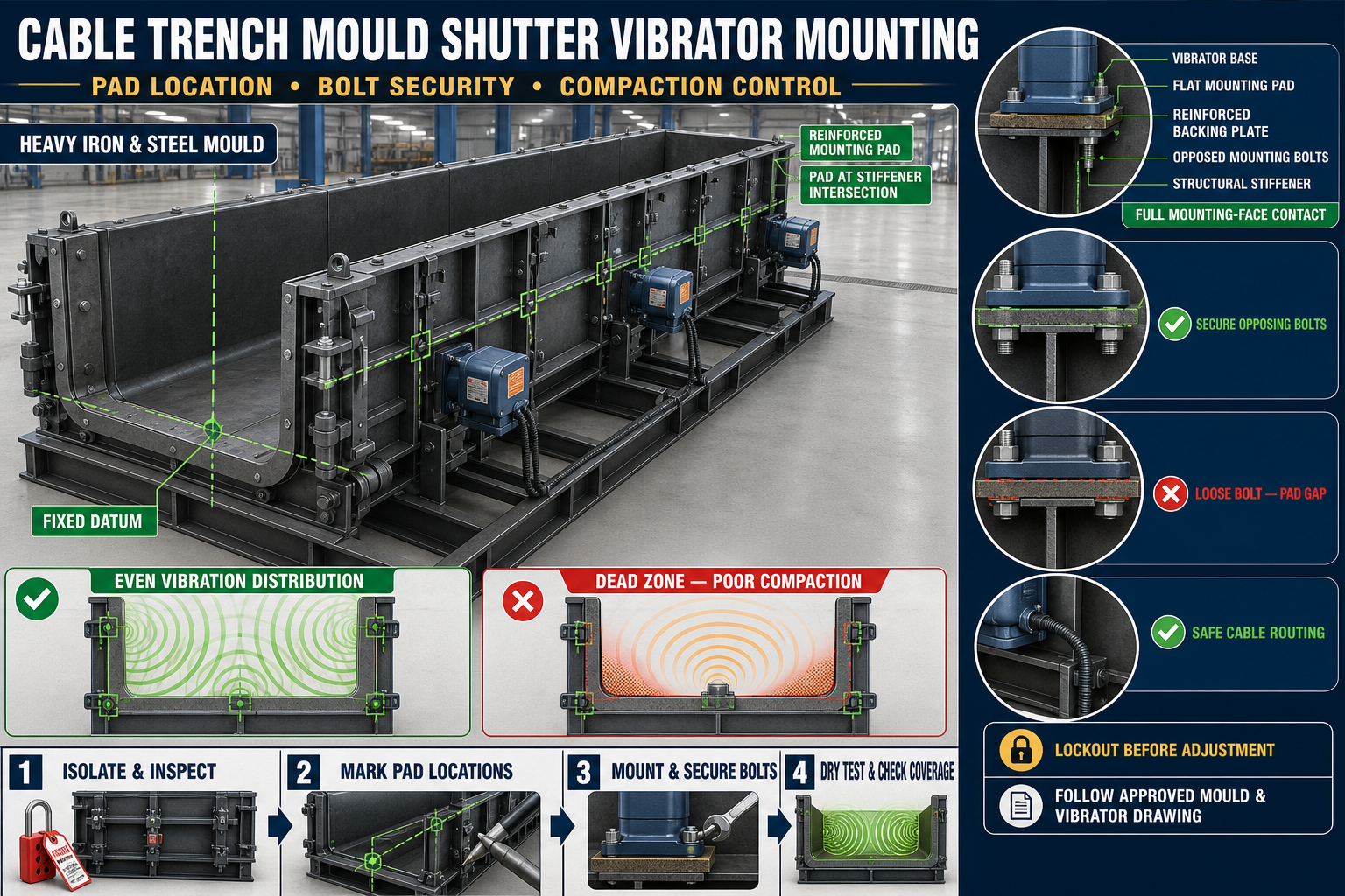
Cable Trench Mould Shutter Vibrator Mounting: Pad Location, Bolt Security and Compaction Control
Cable Trench Mould Shutter Vibrator Mounting Guide
Precast cable trenches are used to protect electrical, communication and utility cables in power plants, industrial projects, substations, railways and infrastructure corridors.
Fresh concrete must be compacted properly around reinforcement, trench corners, wall sections and embedded details. Some heavy-duty cable trench moulds use external shutter vibrators to transfer vibration through the iron mould into the concrete.
The performance of a shutter vibrator depends on its mounting-pad location, connection rigidity, motor orientation and operating procedure. Incorrect installation may create weak compaction zones, excessive noise, loose bolts or structural damage.
This guide explains cable trench mould shutter vibrator mounting, including pad positioning, bolt security, cable routing and compaction control.
What Is a Shutter Vibrator?
A shutter vibrator is an externally mounted vibration unit attached to a mould shutter or dedicated mounting pad.
It transfers vibration through the heavy iron mould plate and structural stiffeners into fresh concrete.
A typical system may include:
• Electric or pneumatic shutter vibrator • Heavy steel mounting pad • Reinforced backing plate • Mounting bolts • Nuts and washers • Locking arrangement • Structural stiffeners • Electrical cable or air hose • Protective guard • Control switch • Junction box • Cable support • Mould shutter • Base frame
The exact configuration should follow the mould and vibrator manufacturer’s approved instructions.
Why Shutter Vibrator Mounting Is Important
Correct mounting helps:
• Transfer vibration efficiently • Reduce energy loss at the connection • Compact concrete near mould walls • Reach corners and narrow sections • Reduce trapped air • Maintain mould stability • Prevent vibrator movement • Reduce bolt loosening • Limit structural damage • Support repeatable production
A powerful vibrator cannot compensate for a weak or incorrectly positioned mounting pad.
Common Mounting Problems
Typical problems include:
• Vibrator mounted on a thin unsupported plate • Pad located away from stiffeners • Loose mounting bolts • Uneven contact between vibrator and pad • Cracked mounting-pad welds • Incorrect motor orientation • Electrical cable touching moving parts • Excessive vibration near one corner • Dead zones at the opposite end • Slurry leakage from loose mould joints • Shutter distortion • Repeated fastener failure
These problems should be corrected before production continues.
Safety Before Inspection
Shutter vibrators contain electrical and mechanical hazards.
Before maintenance:
1. Stop concrete casting and vibration. 2. Disconnect and isolate the electrical supply. 3. Apply the plant’s lockout and tagout procedure. 4. Release pneumatic pressure where applicable. 5. Wait until vibration has completely stopped. 6. Support movable shutters mechanically. 7. Keep personnel away from pinch zones. 8. Inspect cables using qualified personnel. 9. Wear suitable personal protective equipment. 10. Confirm that the mould is empty where required.
Never touch or tighten a vibrator while it is operating.
Inspect the Cable Trench Mould
Before selecting or inspecting vibrator pads, check the complete heavy iron mould.
Inspect:
• Casting plates • Side shutters • Base frame • Longitudinal stiffeners • Cross stiffeners • Hinges • Locks • Flange joints • Alignment pins • Modular connections • Reinforcement clearances • Cover-slab rebate details
The mould structure determines how vibration travels.
Understand the Vibration Path
A shutter vibrator transfers energy through:
1. Vibrator mounting face 2. Steel mounting pad 3. Reinforced backing structure 4. Shutter plate 5. Fresh concrete 6. Reinforcement and embedded components
Loose contact at any stage can reduce compaction and increase noise.
What Is a Vibrator Mounting Pad?
A mounting pad is a reinforced steel plate or bracket welded or bolted to the mould at an approved location. It provides a flat and rigid surface for the vibrator.
A suitable pad should:
• Match the vibrator mounting arrangement • Sit against structural reinforcement • Remain flat • Transfer load into stiffeners • Provide bolt access • Keep the vibrator clear of locks and hinges • Protect cables or hoses • Allow inspection and maintenance
Do not mount a vibrator directly onto a weak unsupported shutter area.
Selecting the Mounting-Pad Location
Pad position should be selected according to:
• Mould length • Mould height • Concrete wall thickness • Stiffener arrangement • Reinforcement congestion • Concrete-placement sequence • Number of vibrators • Required vibration direction • Modular mould joints • Approved engineering design
Do not choose the location only because it is easy to reach.
Mount Pads Near Structural Support
The mounting pad should transfer vibration into strong mould members.
Useful supporting areas may include:
• Intersections of stiffeners • Reinforced shutter zones • Designed cross members • Dedicated vibration brackets • Heavy backing plates
Mounting only on thin plate can cause local flexing instead of useful vibration transfer.
Avoid Critical Mould Components
Do not place a vibrator where it interferes with:
• Hinges • Wedge locks • Hydraulic cylinders • Flange seals • Alignment pins • Lifting points • Reinforcement supports • Cover-slab rebates • Demoulding movement • Operator access
Maintain the clearances required by the approved drawing.
Vibrator Distribution Along the Mould
Long cable trench moulds may require vibration at more than one location. The required arrangement depends on the mould and concrete system.
Possible considerations include:
• Equal coverage along the length • End-wall compaction • Central dead zones • Wall-height differences • Modular sections • Concrete filling sequence • Opposing shutter arrangement • Interaction between vibrators
Do not add additional vibrators without checking the structural and electrical design.
Symmetrical Mounting
Where matching vibrators are fitted on opposite or repeated mould sections, their positions should follow the approved symmetrical arrangement.
Incorrect positioning can create:
• Uneven vibration • Sideways mould movement • Different surface finishes • Unbalanced shutter loading • Loose locks • Unequal concrete compaction
Use fixed datum points to locate each mounting pad.
Mark Pad Positions From a Fixed Datum
A suitable layout process includes:
1. Establish the mould datum. 2. Mark the shutter centreline. 3. Identify structural stiffeners. 4. Mark approved vibrator zones. 5. Confirm clearance from locks and hinges. 6. Compare matching pad locations. 7. Check cable access. 8. Verify the layout against the drawing. 9. Inspect before welding or drilling.
Avoid cumulative measurements along modular sections.
Mounting-Pad Fabrication Inspection
Check the pad for:
• Flatness • Plate distortion • Correct hole pattern • Burr-free holes • Adequate backing support • Cracked welds • Corrosion • Previous repairs • Contact with the vibrator base • Clearance for fasteners
A distorted pad may prevent full mounting-face contact.
Pad Welding and Distortion
Welding heat can distort the shutter or mounting pad.
To control distortion:
• Use an approved welding sequence • Support the shutter correctly • Avoid excessive heat concentration • Balance welds where required • Allow controlled cooling • Recheck pad flatness • Inspect the shutter plate • Verify mould alignment after welding
Do not use uncontrolled heating to straighten the mould.
Check Full Mounting-Face Contact
The vibrator base should sit flat against the mounting pad.
Check for:
• Rocking • Gaps • Paint buildup • Concrete residue • Welding spatter • Burrs • Distorted surfaces • Incorrect washers • Foreign material
A small gap can create impact noise and fastener loosening.
Mounting-Bolt Inspection
Vibrator bolts operate under repeated dynamic loading.
Inspect:
• Bolt grade and specification • Thread condition • Nut condition • Washer contact • Locking arrangement • Bolt length • Hole condition • Corrosion • Previous stretching • Contact with surrounding parts
Only approved matching fasteners should be used.
Do Not Use Random Replacement Bolts
Unapproved fasteners may have incorrect:
• Material strength • Thread type • Length • Head size • Washer arrangement • Locking method • Fatigue resistance
A bolt that physically fits may still be unsuitable for vibration service.
Bolt-Tightening Sequence
A controlled fastening procedure may include:
1. Clean the mounting pad and vibrator base. 2. Position the vibrator correctly. 3. Install all fasteners loosely. 4. Confirm full surface contact. 5. Tighten opposing bolts gradually. 6. Follow the approved sequence. 7. Apply the manufacturer’s specified torque. 8. Install the approved locking arrangement. 9. Recheck after the initial controlled test. 10. Record the inspection.
Do not use assumed torque values.
Signs of Loose Mounting Bolts
Loose bolts may cause:
• Metallic knocking • Vibrator movement • Polished contact marks • Enlarged holes • Damaged threads • Cracked pad welds • Reduced vibration transfer • Electrical cable movement • Bolt or washer loss
Stop operation immediately if the vibrator moves on its pad.
Over-Tightened Bolts
Excessive tightening can:
• Stretch bolts • Damage threads • Distort the mounting pad • Crack the vibrator housing • Reduce clamping reliability • Make maintenance difficult
Use the specified tightening procedure.
Fastener Locking Methods
The approved installation may use:
• Locknuts • Mechanical locking washers • Retaining plates • Thread-locking products • Safety wire • Manufacturer-specific arrangements
Use only the approved method compatible with vibration and maintenance requirements.
Vibrator Orientation
A shutter vibrator should be installed in the orientation specified by the manufacturer.
Orientation can affect:
• Vibration direction • Bearing lubrication • Cable entry • Drainage • Mounting loads • Maintenance access • Protective-cover position
Do not rotate the unit arbitrarily for easier cable routing.
Electrical Cable Routing
Electric-vibrator cables should be protected from:
• Moving shutters • Sharp steel edges • Concrete impact • Hot surfaces • Standing water • Vehicle traffic • Pinch points • Excessive tension • Repeated bending • Vibration abrasion
Use approved cable glands, supports and protective conduits.
Provide a Flexible Cable Section
The cable arrangement should accommodate normal mould movement without pulling the terminal box.
Check:
• Flexible length • Bend radius • Support spacing • Terminal-box connection • Strain relief • Junction-box position • Cable protection • Earthing arrangement
Electrical work should be completed by qualified personnel.
Earthing and Electrical Protection
Verify:
• Equipment earthing • Cable insulation • Protective devices • Control-panel condition • Emergency stop • Motor-protection system • Terminal security • Water ingress protection • Connector condition
Do not operate equipment with exposed or damaged cables.
Pneumatic Vibrator Hose Routing
Where pneumatic vibrators are used, inspect:
• Hose pressure rating • Couplings • Clamps • Kinks • Abrasion • Air leakage • Hose supports • Shutoff valve • Exhaust direction
Release stored air pressure before maintenance.
What Is Compaction Control?
Compaction control means applying enough vibration to consolidate concrete without causing segregation, slurry leakage or mould damage.
Correct compaction should be assessed through:
• Concrete behaviour • Surface finish • Air release • Filling of corners • Reinforcement coverage • Absence of honeycombing • Mould stability • Quality-control results
More vibration is not always better.
Signs of Insufficient Compaction
Possible signs include:
• Honeycombing • Air pockets • Poor corner filling • Rough surfaces • Voids near reinforcement • Uneven concrete density • Incomplete trench edges • Weak-looking surface zones
The cause may involve vibrator location, concrete workability or operating procedure.
Signs of Excessive Vibration
Possible signs include:
• Concrete segregation • Slurry leakage • Aggregate settlement • Excess paste at the surface • Mould-lock loosening • Reinforcement movement • Insert displacement • Excessive noise • Shutter movement • Motor overheating
Stop and review the process if these signs appear.
Dead Zones in Cable Trench Moulds
A dead zone is an area receiving insufficient vibration.
Common locations may include:
• Mould ends • Corners • Areas behind dense reinforcement • Regions far from mounting pads • Modular joints • Cover-rebate details • Local thick sections
Repeated defects at one mould location may indicate a vibration-distribution problem.
Identifying Dead Zones
Use production observations such as:
• Repeated honeycombing location • Air pockets • Different surface texture • Concrete remaining stiff in one area • Uneven air release • Poor corner formation • Quality-test variation
Record each defect by mould position.
Do Not Move the Vibrator Without Investigation
Before relocating a mounting pad, check:
• Concrete mix and workability • Filling sequence • Reinforcement congestion • Existing pad condition • Bolt security • Vibrator operation • Mould contact and locking • Operating time • Motor direction • Electrical supply
A location change should follow engineering review.
Interaction Between Multiple Vibrators
Multiple units may reinforce or oppose each other depending on their position, orientation and operation.
Incorrect coordination can cause:
• Uneven compaction • Excessive mould movement • Resonance • Clamp loosening • Structural fatigue • Noise • Motor overloading
Follow the approved operating sequence and controls.
Controlled Empty-Mould Test
After installation or maintenance, perform a controlled test according to the approved procedure.
Before testing:
1. Confirm the mould is empty. 2. Remove tools. 3. Close and lock shutters. 4. Check all vibrator bolts. 5. Secure cables or hoses. 6. Clear personnel from the mould. 7. Restore power through the approved process. 8. Start the vibrator briefly. 9. Observe movement from a safe location. 10. Stop and isolate before reinspection.
Do not touch the vibrator during or immediately after operation.
Observe During the Empty Test
Check:
• Vibrator security • Mounting-pad movement • Abnormal noise • Shutter movement • Lock security • Cable behaviour • Mould-base stability • Structural resonance • Cracked welds • Bolt loosening
Stop immediately if the unit shifts.
Loaded Production Trial
After a successful empty test, complete a controlled concrete trial.
Monitor:
• Concrete filling • Air release • Corner compaction • Shutter stability • Slurry leakage • Reinforcement movement • Locking points • Vibrator sound • Electrical behaviour • Finished surface after demoulding
Record results before regular production.
Concrete Placement Sequence
Balanced filling helps the vibrator work effectively.
During casting:
• Place concrete progressively • Avoid filling one end completely first • Maintain reinforcement position • Avoid direct impact on inserts • Monitor visible joints • Follow the approved sequence • Stop if shutters move • Keep cables away from concrete placement
The placement procedure should match the mould configuration.
Operating Sequence
The approved sequence may vary depending on the vibrator and concrete system.
Operators should confirm:
• When vibration begins • Which vibrator starts first • Operating intervals • Concrete filling stages • Stop conditions • Required visual checks • Emergency shutdown procedure
Do not develop settings through uncontrolled trial and error.
Temperature Check
A vibrator may become warm during operation, but abnormal heating can indicate:
• Loose mounting • Bearing problems • Electrical issues • Overloading • Incorrect orientation • Excessive operating time • Supply problems
Temperature assessment should follow the manufacturer’s instructions.
Noise Diagnosis
Metallic Knocking
Check loose bolts, pad gaps, cracked welds and moving shutters.
Grinding Noise
Inspect the vibrator bearings and internal condition through qualified personnel.
Rattling
Check guards, cables, locks, washers and surrounding components.
Noise at One Mould Joint
Inspect flange closure, alignment pins and sealing material.
Sudden Sound Change
Stop operation and inspect the complete system.
Slurry Leakage During Vibration
Leakage may indicate:
• Loose shutter locks • Damaged seals • Excessive vibration • Misaligned flanges • Distorted mould plates • Concrete buildup • Loose modular joints
Do not only reduce vibration without inspecting the mould joint.
Inspect Vibrator Mounts After Every Trial
After isolating the system, check:
• Bolt position • Washer marks • Mounting-face contact • Pad welds • Cable glands • Protective covers • Shutter fasteners • Nearby locks • New polished movement marks
Re-tighten only according to the approved procedure.
Common Problems and Corrective Actions
Vibrator Repeatedly Loosens
Check pad flatness, bolt specification, tightening procedure, locking method and excessive resonance.
Concrete Compacts Near the Vibrator but Not at the End
Review pad distribution, filling sequence, concrete workability and reinforcement congestion.
Shutter Plate Vibrates but Concrete Does Not Settle
Check mounting rigidity, vibrator suitability, concrete condition and dead zones.
Pad Weld Cracks
Stop operation and inspect structural support, vibration level, weld design and shutter distortion.
Electrical Cable Repeatedly Fails
Review cable routing, strain relief, vibration abrasion and shutter movement.
Vibrator Produces Excessive Noise
Inspect full mounting contact, loose fasteners, bearing condition and nearby metal contact.
Locks Become Loose
Check vibration level, lock wear, mould alignment and retaining components.
Concrete Segregates
Review vibration intensity, duration, concrete mix and placement procedure.
Preventive Maintenance Checklist
Before Every Use
• Inspect vibrator bolts • Check pad welds • Examine cables or hoses • Verify protective covers • Check shutter locks • Clean mounting areas • Confirm mould stability
Scheduled Maintenance
• Remove and inspect the vibrator • Check mounting-face flatness • Inspect bolt threads • Replace damaged locking components • Examine structural stiffeners • Check electrical insulation and earthing • Inspect bearings according to manufacturer guidance • Review defect locations • Verify pad positions • Conduct controlled tests
When Should Production Be Stopped?
Stop using the shutter vibrator if you find:
• Loose mounting bolts • Cracked mounting-pad welds • Damaged electrical cables • Failed earthing • Exposed connections • Abnormal bearing noise • Excessive heating • Vibrator movement • Distorted shutter plate • Severe mould resonance • Repeated lock loosening • Unsafe pneumatic leakage
Operation should resume only after repair and controlled testing.
Conclusion
Correct cable trench mould shutter vibrator mounting depends on a rigid steel pad, full mounting-face contact, approved fasteners and placement that transfers vibration through the mould’s structural stiffeners.
Compaction quality should be evaluated across the complete cable trench, including corners, mould ends, reinforcement zones and cover-rebate details. Excessive vibration can be as damaging as insufficient vibration.
Paras Steel Industries manufactures heavy-duty iron and structural-steel cable trench moulds according to customer requirements and approved drawings. Correct pad placement, secure vibrator mounting and planned compaction checks can support consistent precast production and cleaner concrete surfaces.